Advertisement
Quick Links
TURBO
s.r.l.
Electronic Control Systems For Dust Collectors
e-mail: info@turbocontrols.it
web: www.turbocontrols.eu
TEL. ++39 (0)362 574024
FAX ++39 (0)362 574092
ECONOMIZER
E2T
24Vdc
25 ÷ 56 OUTPUTS
User Manual
05/01/2016
Manual Release 1.00
Hardware Release 1.01
Advertisement

Related Manuals for Turbo Economiser E2T

Summary of Contents for Turbo Economiser E2T
- Page 1 TURBO s.r.l. Electronic Control Systems For Dust Collectors e-mail: info@turbocontrols.it web: www.turbocontrols.eu TEL. ++39 (0)362 574024 FAX ++39 (0)362 574092 ECONOMIZER 24Vdc 25 ÷ 56 OUTPUTS User Manual 05/01/2016 Manual Release 1.00 Hardware Release 1.01...
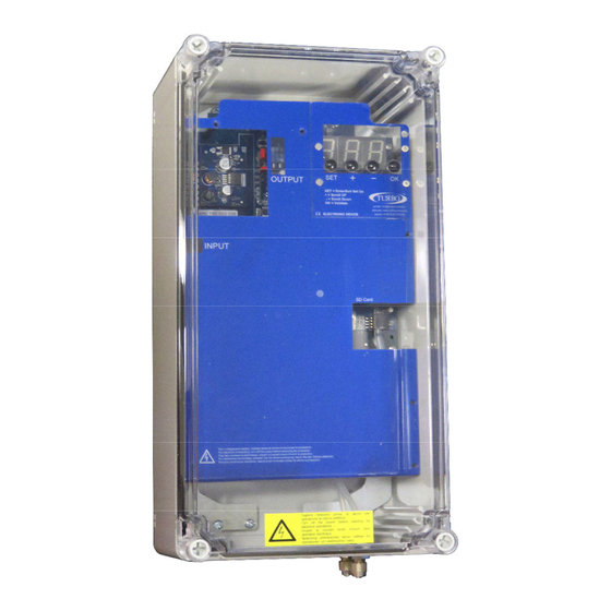
- Page 2 General Description Economizer for controlling the pneumatic cleaning function of industrial dust collection systems. The pressure differential is digitally controlled by an internal transducer allowing to determine filter obstruction with accuracy. The device has three output relays contacts and two digital input contacts. A large, bright display is provided for reading the filter obstruction level, the active solenoid valves and any alarms in any moment.
- Page 3 Electric Specifications W a r n i n g ! R e a d t h e s e c t i o n o n Electric Power i n s t a l l a t i o n b e f o r e c o n n e c t i n g 24 VDC–...
- Page 4 Installation Instructions / Notes And Warnings Protect the device from direct exposure to sunlight. Do not position the device near or directly in contact with sources of heat or electromagnetic fields. Connect the device to power lines other than those for operating motors or other large power devices which could generate network interference.
- Page 5 Display Keypad There are four round buttons on the front panel for controlling the device and turning on the display as shown in the following figure. The SET button enables to enter and exit the programming menu, and activate the manual test of solenoid valve selected in function F06.
- Page 6 List of Functions F01: Configuring the operation mode. Possible values: 0 – Manual (dP excluded) 1 – Automatic (Default) (dP included) 2 – Automatic with forced cycle (dP included) 3 – Proportional (dP included) F02: Solenoid activation time. Possible values: 0.05” – 5.00” step 0.01”. Default = 0.20”.
- Page 7 F14: Post cleaning mode pause time between solenoid valves (fan off). Possible values: 001” – 999” step 1”. Default = 010”. F15: Maintenance frequency expressed in tens of hours Possible values: 001 – 999 step 1. (e.g.: 1=10h, 10=100h). Default = 100 (=1000h). F16: Maintenance deadline alarm enable.
- Page 8 Alarms The unit runs a number of checks during the start-up cycle and during normal operation. The possible alarms and respective solutions are shown in the following table. A. Nr. Description Action - For 24Vdc, switch the device off and move the AC/DC jumpers to DC. Jumper table p.
- Page 9 Minimum dP alarm value ranging from F12 to F21 (warning: the Check the status of the filtering alarm is generated with a fixed elements. delay of 60 seconds). Indicates that a valve in short circuit has been excluded from the cycle.
- Page 10 Description Of Operation The installed SW version and the symbol ---, meaning that coherence between settings stored in E2Prom and the set jumpers is being checked, will appear on the display when the economizer is powered up. A corresponding error code will appear in case of discrepancies between settings (see Alarms Table).
- Page 11 Proportional Mode F01 = 3 With the proportional mode, the economizer will work in full autonomy, initially setting the dP_Start threshold (F08), activation time (F02) and pause time (F03). When the Start Cleaning threshold is exceeded, the solenoid valves are automatically activated in sequence.
- Page 12 Fuse A fuse which can be reset in case of need is located near the power terminal board. Use a delayed fuse 5x20mm as shown in the table on next pages. SD Memory Card The Micro SD memory card slot is located on the bottom right of the control unit under the polycarbonate lid.
- Page 13 Connection Diagram...
- Page 14 Contacts And Relay Terminal Block J4 Enable contact input consensus 14.15 terminals. Is used to activate the control unit remotely, it can be turned on and off remotely. The unit is supplied with a jumper on the two terminals 14:15, without it will not turn on.
- Page 15 Connection Diagram Expansions Expansion Up To 32 Channels Expansion Up To 40 Channels...
- Page 16 Expansion Up To 48 Channels...
- Page 17 Expansion Up To 56 Channels...
- Page 18 Terminal Table To access at the terminal blocks of the control board, unscrewing countersunk screws of the cover panel blue. Main Board Terminal Description Terminal Description Power Supply 24 Vdc Solenoid output 16 Power Supply 24 Vdc Solenoid output 17 Earth (GND) Solenoid output 18 Solenoid output 19...
- Page 19 Expansion Boards Expansion up to 32 channels Expansion up to 48 channels Terminal Description Terminal Description Earth (GND) Earth (GND) Solenoid valve common Solenoid valve common Solenoid output 25 Solenoid output 41 Solenoid output 26 Solenoid output 42 Solenoid output 27 Solenoid output 43 Solenoid output 28 Solenoid output 44...
- Page 20 Installation And Casing Dimensions...
- Page 21 Maintenance Only the fuses, batteries and SD card can be replaced. All other repairs must be done by the manufacturer. Default Settings Function Description Set Value Number Automatic setting using dP (1) or manual (0) 0.20” Solenoid valve activation time Washing pause time between solenoid valves in normal 020”...
- Page 22 Disposal Do not disperse in the environment after use. Dispose of the product according to current regulations for the disposal of electronic equipment. This device is used in a dust collector system and, therefore, it is part of a fixed installation.
- Page 23 Solution Problem FAULT POSSIBLE CAUSE SOLUTION The display does not light Burnt fuse. Check the protection fuse on the power voltage. Check that the power voltage is present and compliant with that required for the device (terminals 1 and 3). The outputs are not Incorrect output voltage.
- Page 24 Declaration Of Conformity Of The Manufacturer The Manufacturer: TURBO s.r.l. The Manufacturer's Address: Via Po 33/35 20811 Cesano Maderno (MB) Italy Declares that: Product Name: Economizer E2T Product Options: Complies with the following directives: Machinery Directive 2006/42/EC 'Electromagnetic compatibility' compliant with...
Need help?
Do you have a question about the Economiser E2T and is the answer not in the manual?
Questions and answers