Table of Contents

Related Manuals for Turbo E2T Series

Summary of Contents for Turbo E2T Series
- Page 1 TURBO s.r.l. Electronic Control Systems For Dust Collectors e-mail: info@turbocontrols.it web: www.turbocontrols.eu Tel. ++39 (0)362 574024 Fax ++39 (0)362 574092 ECONOMISER SERIES USER MANUAL 01/03/2016 Manual Release 1.25 Hardware Release 1.3...
-
Page 2: General Description
General Description Economiser for controlling the pneumatic cleaning function of industrial dust collection systems. The pressure differential is digitally controlled by an internal transducer allowing to determine filter obstruction with accuracy. It has 2 output relay contacts and 2 digital input contacts. - Page 3 Electric Specifications Electric Power • Important: Read the 115 Vac ± 10% 50-60 Hz – 25W • installation instruction section 230 Vac ± 10% 50-60 Hz – 25W • before connecting the device. 24 Vac ± 10% 50-60 Hz – 25W (optional) •...
-
Page 4: Warning Symbols Used In This Manual
Warning Symbols Used In This Manual The information regarding safety are highlighted using the symbols: Warning-Danger Generic - Warning- Risk – Danger Electric Current Dispose according to the standards for electrical and electronic equipment RAAE Installation Rules Notes and Warnings Protect the device from direct exposure to sunlight. - Page 5 The cable glands must be chosen according to the diameter of the cable to be used. The sealing of the press cable is guaranteed by the compression of the rubber gasket that tightens on the outer diameter of the cable. The tightness of the cable gland is guaranteed by the compression of the rubber seal that tightens on the outer diameter of the cable.
-
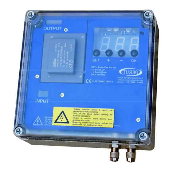
Page 6: Display / Keypad
Display / Keypad There are four round buttons on the front panel for controlling the device and turning on the display as shown in the following figure. The SET button enables to enter and exit the programming menu, and activate the manual testing of select4ed solenoid valve function F06. -
Page 7: List Of Functions
List Of Functions F01: Configuring the operation mode. Possible values: 0 – Manual (dP excluded) 1 – Automatic (dP included) Default 2 – Automatic with forced cycle (dP included) 3 – Proportional (dP included) By setting the Manual Mode, it is necessary change the value of F11 Fan Recognition on 0, detection by contact and not by dP, close together the contacts to 12.13 on J2 terminal block. - Page 8 F13: Number of post cleaning cycles after stopping the fan. Possible values: 01 – 99 step 1. Default = 01. F14: Post cleaning mode pause time between solenoid valves (fan off). Possible values: 001” – 999” step 1”. Default = 10”. F15: Maintenance frequency expressed in tens of hours (e.g.: 1=10h, 10=100h).
- Page 9 Alarms The unit runs a number of checks during the start-up cycle and during normal operation. The possible alarms and respective solutions are shown in the following table. Description Action - For 24 Vdc, switch the device off and move the AC/DC jumpers to DC.
-
Page 10: Description Of Operation
Minimum dP alarm value ranging from F12 to F21 (warning: the alarm is generated Check the status of the filtering elements. with a fixed delay of 60 seconds). Indicates that a valve in short circuit has been excluded from the cycle. The signaling of the code E14 alternates with the indication of the interested output is shown as Uxx where xx is the number of... - Page 11 Proportional Mode F01 = 3 With the proportional mode, the economiser will work in full autonomy, initially setting the dP_Start threshold (F08), activation time (F02) and pause time (F03). When the Start Cleaning threshold is exceeded, the solenoid valves are automatically activated in sequence.
-
Page 12: Connection Diagram
Connection Diagram Pressure Sensor dP + Pressure inlet dirty section dP - Depression inlet clean section... - Page 13 Contacts And Relay Terminal Block J2 Enable contact input consensus 14.15 terminals. Is used to activate the control unit remotely, it can be turned on and off remotely. The unit is supplied with a jumper on the two terminals 14:15, without it will not turn on. Fan contact 12.13 input terminals.
- Page 14 Fuse Table Voltage Value 230 Vac 115 Vac 24 Vdc / Vac Jumper Configuration - Power Input 115 VAC 230 VAC Jumper Configuration - Output 115 VAC 230 VAC 24 VAC 24 VDC...
- Page 15 Installation Casing Dimensions 4 / 8 Outputs – Weight 1.8 Kg...
- Page 16 Installation Casing Dimensions 12 / 16 Outputs – Weight 2.1 Kg...
-
Page 17: Maintenance
Maintenance The only parts which may be replaced are fuses. All other operations must be carried out by the manufacturer. Scrapping Dispose of properly after use. Dispose of the product according to laws in force for electronic equipment. This device is for use in a dust collection system and is therefore part of a fixed installation. -
Page 18: Warranty Exclusions
Warranty The warranty lasts for 2 years. The manufacturer will replace any faulty electronic component at their own facilities only, unless otherwise authorised by the manufacturer. Warranty Exclusions The warranty will be cancelled in case of: • Signs of unauthorised tampering and repairs. •... - Page 19 Problem Solution FAQ Fault Possible Cause Solution Check the protection fuse on the power voltage. Check that the power voltage is The display does not light up. Burnt fuse. present and compliant with that required for the device (terminals 1 and 3). Check that the unit and solenoid vale output voltage Incorrect output voltage.
- Page 20 Declaration Of Conformity Of The Manufacturer The Manufacturer: TURBO srl The Manufacturer's Address: Via Po 33/35 20811 Cesano Maderno (MB) Italy Declares that: Product Name: Economiser E2T Models: E2T 4 - 16 Product Options: Complies with the following directives: Directive 2014/30/EU Electromagnetic Compatibility compliant with Harmonised...
Need help?
Do you have a question about the E2T Series and is the answer not in the manual?
Questions and answers