Advertisement
Quick Links
I
, O
& M
M
NSTALLATION
PERATION
AINTENANCE
ANUAL
P
B
B
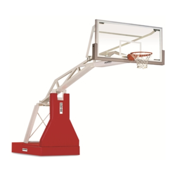
ORTABLE
ASKETBALL
ACKSTOP
No. 1235
INSTALLER NOTE:
Upon completion of the installation/assembly of this portable backstop,
make sure this instruction manual is in the possession of the owner or
facility manager, to save for future reference.
INST 00257 127
© 1997 PORTER ATHLETIC EQUIPMENT COMPANY. ALL RIGHTS RESERVED.
12-1-1997
Advertisement

Related Manuals for Porter 1235


Summary of Contents for Porter 1235
- Page 1 Upon completion of the installation/assembly of this portable backstop, make sure this instruction manual is in the possession of the owner or facility manager, to save for future reference. INST 00257 127 © 1997 PORTER ATHLETIC EQUIPMENT COMPANY. ALL RIGHTS RESERVED. 12-1-1997...
- Page 2 Your athletes and spectators should enjoy thousands of hours of practice and competition on Porter equipment. This booklet is intended to be used for the initial set-up of your No. 1235 backstop, and as a guide for the safe use and maintenance of the unit. PLEASE READ THESE INSTRUCTIONS CAREFULLY AND COMPLETELY BEFORE BEGINNING THE SET-UP WORK, OR MAINTENANCE, OF THIS UNIT.
-
Page 3: General Operating Information
GENERAL OPERATING INFORMATION Electrical Supply Connect control panel to 120 volt AC, 60HZ, 20AMP circuit, with a maximum length to power source of 50 feet. If additional cord beyond 50 feet is required, a minimum power cable of #10awg is required to prevent power loss and possible damage to controls and motor assembly. - Page 4 No. 1235 PORTABLE BASKETBALL BACKSTOP ASSEMBLY, ADJUSTMENT, OPERATION and MAINTENANCE INSTRUCTIONS WARNING READ THESE ASSEMBLY AND OPERATING INSTRUCTIONS IN THEIR ENTIRETY, BEFORE ATTEMPTING TO UNPACK, ASSEMBLE, OR OPERATE THIS PORTABLE BACKSTOP, TO AVOID POSSIBLE INJURIES, OR DAMAGE TO THE EQUIPMENT.
- Page 6 No. 1235 PORTABLE BACKSTOP ASSEMBLY INSTRUCTIONS 1. Unpack and identify all parts (refer to packing list) on page 4. 2. Position the unpacked glass backboard (#16) on its cardboard packing carton in front of portable backstop frame (#1). Remove (2) 3/8" x 1" hex head cap screws from back of glass bank.
- Page 7 6. Attach the two (2) hinge weldments (#3) into the slots in the upper corners of the glass backboard using four (4) 3/8" x 1-1/4" long carriage bolts (#8), 3/8" hex nuts (#9), and 3/8" lockwashers (#11). Finger tighten only. See Illustration “B”. 7.
- Page 8 ILLUSTRATION "C" ADJUST BACKBOARD YOKE FRAME FRONT-TO-BACK TO PLUMB FACE OF BACKBOARD 9. Remove the two goal mounting bolts (#18, #19, #21, #22) assembled in Steps 3 & 4. 10. You are now ready to mount the goal. Carefully hold the goal (#17) against the face plate of the backboard (#16) and insert the two bolts (#18) through the goal, backboard and the backstop mounting plate (refer back to Illustration “A”).
- Page 9 ILLUSTRATION "D" ASSEMBLE PADDING AND ENCLOSURE PANELS TO FRAME AS FOLLOWS 17. Position base pads around base so that front pad (#24) extends over edges of long side pads (#25). Side pads (#25) will extend over edges of rear pad (#26). Assemble front pad (#24) to front of base (#1) using 1/4" x 4" lg. hex head lag screw (#14). Next attach side pads (#25) to base (#1) using #12 x 1"...
- Page 10 IMPORTANT - UPON FINAL SET UP OF THIS UNIT, SHOW THE INDIVIDUAL WHO WILL OPERATE THIS UNIT HOW TO PROPERLY OPERATE THIS UNIT AND READ THE WARNING LABELS TO HIM/HER EXPLAINING THE NECESSITY TO FOLLOW SAFE OPERATING PROCEDURES. THESE INSTRUCTIONS MUST BE GIVEN TO AN OFFICIAL IN CHARGE OF THE FACILITY TO KEEP FOR FUTURE REFERENCE.
- Page 11 1235 MAINTENANCE CHECK LIST 1. Check key switch, electrical connections for proper operation, tightness and integrity. 2. Operate unit, check operation, up cycle, and down cycle. 3. Check hydraulic system for leaks, check hoses, cylinders, seals, and motor. Check level of hydraulic fluid. (Use hydraulic fluid, available at most auto part stores, if necessary).
- Page 12 1235 ELECTRIC TROUBLE SHOOTING GUIDE PROBLEM #1 Rotate key switch to up or down and motor does not run. POSSIBLE CAUSE: No main power. Break in extension cord. SOLUTION: Check receptacle and extension cord with voltage meter for 120V 60Hz.
- Page 13 1235 HYDRAULIC TROUBLE SHOOTING GUIDE PROBLEM #1 Unit comes down to fast when key is turned to down cycle. SOLUTION: Turn in slightly knob on flow control valve located at back end of large mast cylinder. PROBLEM #2 Unit goes up on casters as unit is coming down.
- Page 15 01235-914 PORTABLE HYDRAULIC FIELD-HOUSE BACKSTOP WITH 8'-0" EXTENSION...
- Page 16 01235-108 PORTABLE HYDRAULIC FIELD-HOUSE BACKSTOP WITH 10'-8" EXTENSION...
- Page 17 01236-300 FLOOR ANCHOR SYSTEM FOR PAIR OF No. 01235-914 PORTABLE BACKSTOPS...
- Page 18 TIE-DOWN SYSTEM FLOOR ANCHOR SYSTEM SUPPLIED WITH No. 01235-108 PORTABLE BACKSTOP...
- Page 19 SHOT CLOCK WITH SUPPORT ASSEMBLY AND CONTROL, WITHOUT GOAL LIGHT SHOT CLOCK WITH SUPPORT ASSEMBLY AND CONTROL, WITH GOAL LIGHT 01237-100 and 01237-300 SHOT CLOCK WITH SUPPORT ASSEMBLY FOR No. 1235 PORTABLE BACKSTOPS...
- Page 20 State of California to cause cancer and birth defects or other reproductive harm. For more information go to www.p65warnings.ca.gov. Porter Athletic Equipment Company 2500 South 25 Avenue, Broadview, IL U.S.A., 60155 Toll Free: (800) 947-6783 • Phone: (708) 338-2000 • Fax: (708) 338-2060 www.porter-ath.com...
Need help?
Do you have a question about the 1235 and is the answer not in the manual?
Questions and answers