Table of Contents
Advertisement
Advertisement
Table of Contents

Subscribe to Our Youtube Channel
Related Manuals for NASA Marine CLIPPER


Summary of Contents for NASA Marine CLIPPER
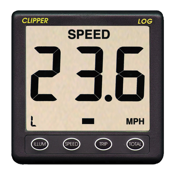
- Page 1 CLIPPER COMPASS TRUE ILLUM STEER CLIPPER MARINE STEERING COMPASS...
-
Page 3: Table Of Contents
TABLE OF CONTENTS PAGE INTRODUCTION PRE-TEST OF INSTRUMENT INSTALLATION OF SENSOR INSTALLING THE DISPLAY NORMAL OPERATION CHANGING THE BACKLIGHT SETTING CHANGING THE DAMPING ASSISTED STEERING SETTING THE DESIRED HEADING SWITCHING ASSISTED STEERING OFF HEADING ALARM SETTING OR STOPPING THE ALARM... - Page 4 PAGE ENGINEERING ADJUSTING MAGNETIC VARIATION MAGNETIC OR TRUE READOUT SETTING THE STEERING SENSITIVITY COMPASS ERROR CORRECTIONS SETTING THE COMPASS RING SETTING THE COMPASS COMPENSATION VALUES HEADING ADJUSTMENT REPEATER FACILITY...
-
Page 5: Introduction
INTRODUCTION The Clipper Compass is supplied complete with display unit, sensor unit, and Mounting kit. It is designed to operate from the vessel’s 12V battery supply. PRE-TEST OF INSTRUMENT Before mounting the units, check that the instrument is complete and undamaged. -
Page 6: Normal Operation
NORMAL OPERATION When power is applied to the Clipper Compass, it executes a comprehensive internal test routine. It then displays the heading. When first powered up, the displayed heading may not be correct until the Compass alignment is done (see Engineering, below). -
Page 7: Changing The Damping
ASSISTED STEERING Assisted steering means using the Clipper Compass to show errors from a chosen heading, and the direction to steer to bring the vessel back to the chosen heading, which is marked by the lubber line at all times. -
Page 8: Setting The Desired Heading
Lubber Line Dead-ahead, within error setting TRUE ILLUM STEER Figure 3 - Dead-ahead indication. If the error increases beyond 180°, the error display reverses to show that the shortest route back to the desired heading is now using the opposite tiller. 2 13 TRUE TRUE... -
Page 9: Switching Assisted Steering Off
TRUE ILLUM STEER FIGURE 5 - Vessel heading aligned with setting. SWITCHING ASSISTED STEERING OFF At any time, while Assisted Steering is operating, pressing STEER switches it off. Pressing STEER again switches it back on again, but with the reference heading updated to the heading which is displayed when STEER is pressed. -
Page 10: Engineering
ILLUM STEER FIGURE 6 - Alarm Boundaries set +/- 9° ENGINEERING Engineering settings means those adjustments which seldom need changing, but which affect how the unit operates. The settings (as are all those which can be selected in normal operation too) are stored even when the power is disconnected. There are four operating characteristics which can be set in Engineering: Magnetic or True heading display;... -
Page 11: Magnetic Or True Readout
-6. 5 MAG. ILLUM STEER FIGURE 7 - Magnetic Variation Display Positive numbers represent Westward variations, and negative numbers (as shown on Figure 7) represent Eastward variations. Each press of INC or DEC alters the stored variation in steps of 0.1°. The fractional value is always repeated in the backlight digit (as shown on Figure 7). -
Page 12: Compass Error Corrections
North, and the accuracy of readings at other points of the compass. These errors can be compensated automatically in the Clipper compass if the vessel can be pointed accurately in particular directions by reference to known geographical features. -
Page 13: Setting The Compass Ring
If, after setting North on the compass ring correctly, it is found that there are significant errors at other points of the compass, these errors can be compensated. This compensation is done by logging the actual readings when the vessel is correctly aligned at the principal directions 45°... -
Page 14: Heading Adjustment
REPEATER FACILITY The Clipper compass display unit takes in un-compensated magnetic readings from the sensor unit, and transmits the compensated (if the compass has been swung) heading and the magnetic variation stored in the unit in a standard NMEA 0183... - Page 16 Prior to unpacking this instrument read and fully understand the installation instructions. Only proceed with the installation if you are competent to do so. Nasa Marine Ltd. will not accept any responsibility for injury or damage caused by, during or as a result of the installation of this product.
Need help?
Do you have a question about the CLIPPER and is the answer not in the manual?
Questions and answers