
Related Manuals for NASA Marine CLIPPER


Summary of Contents for NASA Marine CLIPPER
- Page 1 DESIGNED AND MANUFACTURED IN ENGLAND ILLUM SCALE CLIPPER REPEATERS...
-
Page 2: Table Of Contents
INTRODUCTION INSTALLING THE REPEATER UNIT NORMAL OPERATION - ALL UNITS CHANGING THE BACKLIGHT SETTING ENGINEERING - ALL UNITS COMPASS REPEATER OPERATION WIND SPEED AND DIRECTION REPEATER OPERATION CHANGING THE POINTER SIZE CHANGING THE POINTER STYLE CHANGING THE SPEED SETTING CLOSE HAULED REPEATER OPERATION LOG REPEATER OPERATION GETTING STARTED ECHOSOUNDER REPEATER OPERATION... -
Page 3: Introduction
They require no other connections, because they get their power and signals from the master units, which are in turn powered by the vessel's power supply. Clipper Repeater units must be matched to the master units they are connected to. -
Page 4: Normal Operation - All Units
In the Clipper Log repeater, no Engineering settings can be done, to prevent errors confusion between the two units. In the Clipper Wind Repeater, no Engineering functions are available, because the dead-ahead position should be set from the master unit alone. -
Page 5: Compass Repeater Operation
COMPASS REPEATER OPERATION The Clipper Compass Repeater is a fully independent display with all of the functions of the master unit. Connect the repeater as per the wiring diagram below. Note - if a magnetic variation value is programmed in the master unit, ensure the repeater is set to the same value. Follow the... -
Page 6: Wind Speed And Direction Repeater Operation
Setting the Arrow pointer style CHANGING THE SPEED SETTING The Clipper Wind Repeater can display wind speed measurements in miles per hour (MPH), nautical miles per hour (knots, shown as KTS), and metres per second (m/s). Pressing SCALE switches between knots, miles per hour, and metres per second. The choice is always saved so the unit operates as set whenever it is powered up again, and is not dependent on the setting of the master unit. -
Page 7: Close Hauled Repeater Operation
CLOSE HAULED AND WIND SPEED AND DIRECTION REPEATER CONNECTIONS FOR USE WITH OTHER MANUFACTURERS NASA MARINE NMEA INSTRUMENT: REPEATER BLACK WIRE NEGATIVE 12V POSITIVE 12V RED WIRE BLUE WIRE NMEA INPUT NASA NMEA REPEATER CABLE Blue Black Screen White Blue Plug into Repeater socket of Clipper NMEA instrument... -
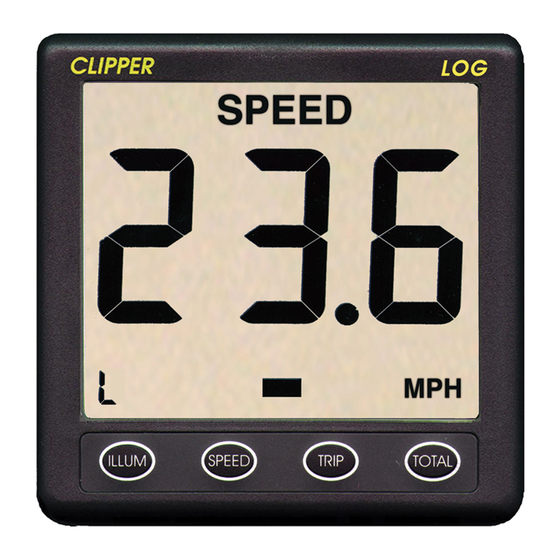
Page 8: Log Repeater Operation
LOG REPEATER OPERATION GETTING STARTED When the Clipper Log is first turned on with the Repeater connected, it automatically performs a number of self-test processes, and after a brief delay switches on the backlight illumination at the factory pre-set level. The Repeater then displays the word “on” until it acquires data from the master unit. -
Page 9: Changing Depth Alarm Settings
CHANGING DEPTH ALARM SETTINGS At any time during normal operation of the unit, it is a simple matter to set an alarm for too shallow and another alarm for too deep. The alarm settings can be different from the setting of the master's alarm setting. -
Page 10: Activating Depth Alarms
ACTIVATING DEPTH ALARMS At any time, the deep and shallow alarms may be activated or de-activated together at the set levels by pressing the DEEP and SHALL buttons together. When alarms are active, a bell symbol is displayed, but is absent when alarms are de-activated. Whenever the measured (and averaged) depth is at, or shallower than, the shallow alarm setting, the alarm sounds, and the word SHALLOW is shown. - Page 11 Only proceed with the installation if you are competent to do so. Nasa Marine Ltd. will not accept any responsibility for injury or damage caused by, during or as a result of the installation of this product. Any piece of equipment can fail due to a number of causes.
- Page 12 Declaration of Conformity NASA Marine Ltd declare this product is in compliance with the essential requirements of R&TTE directive 1995/5/EC. The original Declaration of Conformity certificate can be requested at info@nasamarine.com THIS PRODUCT IS INTENDED FOR USE ONLY ON NON SOLAS VESSELS...
Need help?
Do you have a question about the CLIPPER and is the answer not in the manual?
Questions and answers