
Subscribe to Our Youtube Channel
Related Manuals for Supore ST-1200

Summary of Contents for Supore ST-1200
- Page 1 Optical Scanner ST-1200 OPERATION MANUAL SHANGHAI SUPORE INSTRUMENTS CO., LTD. Http://www.supore.com REV.20180702...
-
Page 2: Preface
Preface Product Instruction Dear Customer: Thank you for choosing our products and trust in our company. ST-1200 optical scanner is a device designed specifically for the glasses store, lens template scanning contour, contour data modification, profile data of power down storage, optical instrument center. - Page 3 2. The use of environmental products(please try to avoid using the machine in the following hazardous conditions) A. Outside the specified temperature range B. Fiercely vibration C.The sun(ST-1200 belongs to the optical instrument, please selectthe darkroom) D. Dust/Smoke E.Moist 3. Note the use of products A.
- Page 4 bottles, cups, etc. on the machine, if the metal material or the flow of liquid into the machine, may cause a fire or electric shock; E. Do not scratch, damage, change the power cable in the power line, don’t put too much weight, pulling, bending power cable, this may cause a fire or electric shock;...
-
Page 5: Table Of Contents
Contents Preface ........................1 Product Instruction ....................1 Security information ..................... 1 1 Instruction of machine..................5 1.1 Main parts(Indicate the name of major external components and graphic) ..........................5 Use ........................ 6 2.1 Install ....................... 6 2.1.1 Instrument installation ................6 2.2 Instrumenttation .................... -
Page 6: Instruction Of Machine
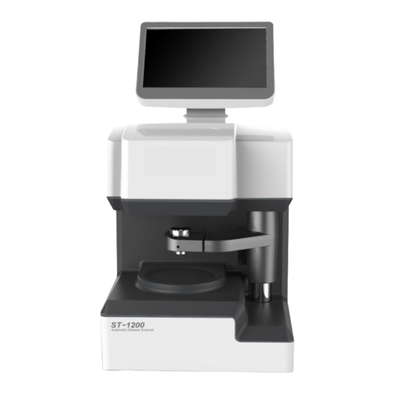
1 Instruction of machine Main parts ( Indicate the name of major external components and graphic) (10) (7) (8) Graphic illustration: (1) Display(touch screen) (2) Suction cup holder (3) Lens carrier (4) The rotary shaft of center meter (5) Ground lead (6) USB rim(reserve) (7) Communication port1(COM1)... -
Page 7: Use
2.1 Install 2.1.1 Instrument installation Illustration: A. Choose a fixed, rigid platform level, should ensure that the platform is fixed, strong; B. One end of a communication line to connect the scanner, the other end is connected with the grinding machine; C. -
Page 8: Instrumenttation
Scanner interface Chart 2-2 2.2 Instrumenttation 2.2.1 Main interface Menu Data modification Center meter Machining lens minimum diameter Symmetry Scanning template Right Left Bridge Data half-pupillary half-pupillary download1 distance distance ight Data Left pupillary height pupillary height download1 Chart 2-3... -
Page 9: Scanning Lens Template
2.2.2 Scanning lens template A. Click on the main interface button, enter the lens template scanning interface; B. Use of the focal length of the lens template for management; C. Remove the lens in the lens carrier template, template, convex concave upward downward. - Page 10 Notice: 1. Lens carrier must be kept clean and clean; 2. Scanning contour, the edge of the lens can not have any dust and dirt. Fig. 2-5 Bridge input Half-PD input...
-
Page 11: Template Date Modification (Special Lens)
Fig. 2-6 Fig. 2-7 input 2.2.3 Template date modification (special lens) A. Click on the main interface button ,enter into data modification interface;... - Page 12 Memory data Angle rotation Memory data search Template data save Width Angle modification rotation Height Half-height modification modification Width and Height modification Caution: The modification is completed, need to reset the interpupillary distance(PD), (HD), nose high pupil distance (DBL), to transfer data to the grinding machine.
-
Page 13: Fix Center
2.2.4 Fix center A. Click on the main interface button , enter a fixed center mode; Left or Right Geometric center model contrast Optical center mode B. Suction cup holder; Note: suction cup direction, concave point to the left C. Select the geometric center mode, the rotary swing arm, and the... - Page 14 suction cup. D. Take the lens. Cautions: The default mode (two centering instrument geometric center mode and optical center mode) 1 Geometric center mode (manual shift) lens edger processing mode 2 Optical center mode (automatic shift center) lens edger processing mode 3 When the optical center mode is selected, the data download of the grinding machine needs to be reset the value of △X、△Y、DBL.
-
Page 15: Menu
2.2.5 Menu A. Click on the main interface button , enter into menu; Size compensation Center meter calibration Size calibration Memory data export Language calibration Memory data import 2.2.6 Size correction A. Click menu interface button , enter into size correction interface;... -
Page 16: Calibration Of Center Meter
2. Red circle and the school board coincide, click save, system automatic correction. 1. Move calibrating board, click + - button, adjust the red circle and the calibrating board overlap 2.2.7 Calibration of center meter A. Click menu interface button , enter the dimension calibration interface;... - Page 17 Regulating knob C. Adjust the level, vertical red line and black line overlap, click the save button; 3.The level of preservation of red and black vertical should be overlap,then save. 1. Adjust the vertical red line and black line overlap. 2 .Adjust the level of the red line coincides with the black line.
-
Page 18: Performance Parameter
3 Performance parameter Exterior dimension: 217× 232× 413mm; Measuring range: lens template L ≤70mm; W≤70mm; Weight: 10Kg Voltage: The power adapter Input: AC100~240V (50~60Hz) ; Output: DC19V/4.7A; Electric power consumption: ≤50W Working condition: 5℃~40℃ Attachment list (packing parts) Name The power adapter The calibration of size RS232 Communication line...
Need help?
Do you have a question about the ST-1200 and is the answer not in the manual?
Questions and answers