Table of Contents

Summary of Contents for Jetvent Fans JVEC-LP
- Page 1 Installation Guide Models: JVEC-LP / JVEC-SP / JVEC-HP May be covered by the following United States and International Patents: D631148S, 138172, 001790452-001, 338608 and other patents pending jetventfans.com JetVent is a Registered Trademark...
- Page 2 WARNING: To reduce the risk of fire, electric shock, and injury to persons, JetVent Fans must be installed only with controllers supplied by Zoo Fans. Other parts cannot be substituted—they may cause injury and will void product warranties.
- Page 3 WARNING: Stay alert and use common sense when installing, operating and servicing fans. Do not operate, install, or service fans if tired or under the influence of drugs, alcohol, or medication. CAUTION: Only operate the fan within the ranges specified on the motor’s type plate. WARNING: Do not flex or bend the blades or fan brackets when installing, adjusting, or cleaning the fan.
- Page 4 RENSEIGNEMENTS IMPORTANTS EN MATIERE DE SECURITE LIRE ET CONSERVER CES INSTRUCTIONS AVERTISSEMENT - POUR RÉDUIRE LE RISQUE DU FEU, LA DÉCHARGE ÉLECTRIQUE et la BLESSURE AUX PERSONNES: Le travail d'installation et le câblage électrique doivent être faits par la personne (s) qualifiée conformément à tous les codes applicables et des normes.
- Page 5 AVERTISSEMENT: Ne pas installer ce ventilateur dans une zone de cuisson. AVERTISSEMENT: Ne pas faire fonctionner le ventilateur dans des espaces présentant des matières dangereuses ou explosives et des vapeurs. DANGER: Equipement rotatif. La mort, les blessures graves et les dommages matériels peuvent résulter. •...
-
Page 6: Table Of Contents
STEP 1: HANGING THE FAN ..............................3 STANDARD INSTALLATION METHOD ........................... 3 SOUND SENSATIVE INSTALLATION ............................3 JetVent Fans Do’s and Don’ts: ............................. 4 STEP 2: WIRING FAN MAINS ..............................5 STEP 3: WIRING FAN SPEED CONTROL SIGNAL ........................5 OPTION 1 - Wiring 10k Ohm Potentiometer ........................ -
Page 7: Pre-Installation
PRE-INSTALLATION The safe installation and operation of equipment supplied by Zoo Fans is the responsibility of the system designer, installer, maintainer, and operator (collectively, the “User”). The need for protective safety accessories to meet company standards, applicable codes, and the requirements of the Occupational Safety and Health Act (“OSHA”) must be determined by the User since safety requirements may vary depending on the location and application of the equipment. -
Page 8: Jetvent Fans Specifications
You may also contact your Zoo Fans’ representative or Zoo Fans directly if you require assistance. Remember, the number of JetVent Fans required for the job, as well as where they are hung, will depend on a number of variables, some of which are: •... -
Page 9: Installation
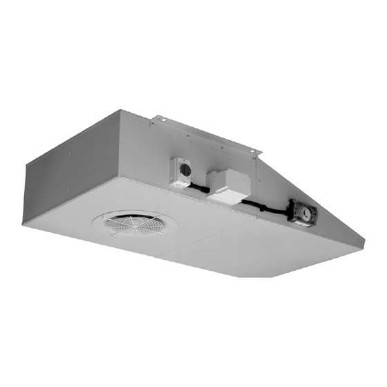
INSTALLATION STEP 1: HANGING THE FAN Mounting Points are illustrated in Red. Two sets of holes are provided on the unit, one is a 13mm hole to be used for mounting directly via hanger rods or bolts, and the other is a 25mm Hole to support the fan with anti-vibration mounts (close up of yellow box Illustrated on the right). -
Page 10: Jetvent Fans Do's And Don'ts
JETVENT FANS DO’S AND DON’TS: Page 4... -
Page 11: Step 2: Wiring Fan Mains
STEP 2: WIRING FAN MAINS The JetVent Fans are equipped with EC motors that will accept a range of voltages. See below: 380 – 480 Volts 3-Phase 50/60 Hertz Alternatively, these motors will accept DC voltage. Please contact ZOO Fans for details. • Electrical connection must be made according to Illustration 8, the wiring diagram below:... -
Page 12: Option 1 - Wiring 10K Ohm Potentiometer
OPTION 1 - Wiring 10k Ohm Potentiometer Din1 Din2 Ain1 Ain1 Ain2 Ain2 Aout Fault Fault (D+) (D-) Output +10VDC (0-10VDC) OPTION 2 - Wiring 0–10 Volt DC Analog Signal Din1 Din2 Ain1 Ain1 Ain2 Ain2 Aout Fault Fault (D+) (D-) Input (0-10VDC) Page 6... -
Page 13: Option 3 - Wiring 4-20Ma Current Signal
OPTION 3 - Wiring 4-20mA Current Signal Din1 Din2 Ain1 Ain1 Ain2 Ain2 Aout Fault Fault (D+) (D-) Input (4-20mA) OPTION 4 - Wiring MODBUS Control Signal Din1 Din2 Ain1 Ain1 Ain2 Ain2 Aout Fault Fault (D+) (D-) Page 7... -
Page 14: Fieldbus/Modbus Communication Cabling
Fieldbus/Modbus Communication Cabling The controller is able to communicate using Modbus RTU (RS485) to JetVent Fans, Vacon Variable Speed Drives (VSDs), and fieldbus sensors. Devices must be connected in a daisy chain with the controller at the start of the chain. No star connections are §... - Page 15 The shield must always be connected to the Ground (GND) terminal at each device. § Avoid unsheathing the communications cable for an excessive length (>20cm) § The shield must NEVER be connected to an electrical protective earth point § Termination Communication cables must be terminated with 120 ohm ¼...
-
Page 16: Step 4: Sensor Wiring
STEP 4: SENSOR WIRING The JetVent Fans are capable of wiring two (2) sensors directly to the fan. IMPORTANT NOTE: The combined sensor load must not be greater than 70mA. SENSOR 1 Din1 Din2 Ain1 Ain1 Ain2 Ain2 Aout Fault Fault (D+) (D-) SIG +... -
Page 17: Step 5: Final Installation Step
STEP 5: FINAL INSTALLATION STEP IMPORTANT: To enable the selected speed control signal, a jumper wire MUST be installed, as shown below: Din1 Din2 Ain1 Ain1 Ain2 Ain2 Aout Fault Fault (D+) (D-) Place a jumper wire here WARNING: Never apply line voltage to the digital input *Optional Fire Alarm Relay (24VDC) Control Wiring... - Page 18 BROUGHT TO YOU BY THE FAN EXPERTS AT 1650 38 St. Suite 201W Boulder, CO 80301 303.557.1852 zoofans.com Copyright ©2018 ZOO Fans Inc. All Rights Reserved. Rev: 20192901...
Need help?
Do you have a question about the JVEC-LP and is the answer not in the manual?
Questions and answers