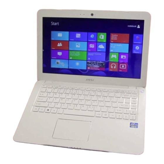
Summary of Contents for MSI MS-1358
- Page 1 S30 (MS-1358) Disassemble Guide ■1、BATTERY ■2、KEYBOARD ■3、UPPER CASE ■4、HDD MODULE ■5、LOWER CASE ■6、WLAN MODULE ■7、MOTHER BOARD AND TOUCHPAD MODULE ■8、LCD MODULE...
- Page 2 S30(MS-1358)Disassemble Guide 1、BATTERY 1.1:Move the “Unlock’ button base on left picture shows. 1.2:Release the “Release” button and move the battery pack base on left picture. Component Battery Pack S9N-2141400-SB3 1.3:Remove the 6 screws (M2*3mm). Attention: the screw driver touque is: 1.5-2.0Kgf-cm...
-
Page 3: Remove The Keyboard
S30(MS-1358)Disassemble Guide 2、KEYBOARD 2.1:Remove the Keyboard. 2.2:Firstly push the handspike on two sides of the K/B cable connector according to the direction as pic shows; then remove the cable. Component Keyboard S1N-2EUS341-SA0... -
Page 4: Upper Case
S30(MS-1358)Disassemble Guide 3、UPPER CASE 3.1:Remove the 7 screws (M2*3mm) and 1 screw (M2*6mm).. Attention: the screw driver torque is: 1.0-1.5Kgf-cm Attention: the screw driver torque is: 1.5-1.8Kgf-cm Component Screw E43-1206001-H29 Screw E43-1203003-H29 3.2:Disconnect Touchpad Cable. - Page 5 S30(MS-1358)Disassemble Guide 3.3 : When remove the Upper case, first remove the two sides, then remove the down side, last detach the Upper case down side from Lower case. Attention: Don’t use the heavy strength to pull the Upper case; and the Touchpad cable is connected with the main board.
-
Page 6: Hdd Module
S30(MS-1358)Disassemble Guide 4、HDD MODULE 4.1:Remove the HDD Module according to the direction as pic shows; Component HDD Module S71-2450547-W36 4.2:Remove the DRAM Module according to the direction as pic shows; Component DRAM Module S7C-S45AH02-E54... -
Page 7: Lower Case
S30(MS-1358)Disassemble Guide 5、LOWER CASE 5.1:Remove the 3 screw(M2*3mm) Attention: the screw driver torque: 1.0-1.5Kgf-cm Component Heatsink E31-0802443-Y31 Screw E43-1203003-H29 5.2:Remove the 2 screw(M2*3.5mm) Attention: the screw driver torque: 1.0-1.5Kgf-cm Component Screw E43-1203501-H29 5.3:Remove the I/O Board Component I/O Board 607-1358B-01S... - Page 8 S30(MS-1358)Disassemble Guide 5.4:Remove LVDS Cable. Component LVDS Cable K19-3023005-V03 5.5:Remove Power Cable. 5.6 : Remove Camera Cable and Speaker Cable.
-
Page 9: Wlan Module
S30(MS-1358)Disassemble Guide 6、WLAN MODULE 6.1:Remove the 2 screw(M2*3.5mm) Attention: the screw driver torque: 1.0-1.5Kgf-cm Component Screw E43-1203501-H29 6.2:Remove the Wlan board as left pic shows, then remove the two side wireless card antenna as pic shows. 6.3 : Remove 2 screw (M2*3.5mm), then remove the WLAN module according to the direction of pic shows. - Page 10 S30(MS-1358)Disassemble Guide 6.4 : Remove the 2 screw(M2*3.5mm), then remove the Power Board Attention: the screw driver torque is 1.0-1.5Kgf-cm Component Power Board 607-1358A-01S Screw E43-1203501-H29 6.5:Remove the 3 screw (M2*3.5mm), Attention: the screw driver torque is 1.0-1.5Kgf-cm Component Screw E43-1203501-H29 6.6:Disconnect Fan Cable,then remove the FAN..
- Page 11 S30(MS-1358)Disassemble Guide 7、MOTHER BOARD AND TOUCHPAD MODULE 7.1:Disassemble the main board to Lower case Component Main Board 607-13581-01S 7.2 : Remove the 2 screw(M2*3.5mm), then remove the Speaker Module. Attention: the screw driver torque is 1.0-1.5Kgf-cm Component Screw E43-1203501-H29 Speaker S33-A020213-F33 7.3:Remove the 4 screw(M2*3mm), then remove...
-
Page 12: Lcd Module
S30(MS-1358)Disassemble Guide 8、LCD MODULE 8.1:Remove 8 screw (M2*3.5mm), then remove the LCD module according to the direction of pic shows. Component LCD Moduel S1J-342G003-A90 Screw E43-1203501-H29 8.2:Remove the 2 LCD Hinge cap. Component Hinge cap E2P-3580311-TA2 8.3: Remove the LCD bezel. - Page 13 S30(MS-1358)Disassemble Guide 8.4:Remove the 6 screws (M2*3.5mm) Attention: the screw driver torque is 3.0-3.5Kgf-cm Component Screw E43-1203501-H29 Hinge R E2M-3580311-G60 Hinge L E2M-3580211-G60 8.5:Remove the display module from LCD cover; 8.6 : Remove the LVDS cable from display module; Component...
- Page 14 S30(MS-1358)Disassemble Guide 8.7:Remove the MIC Module as left picture show Component MIC Module S34-2100901-N44 8.8 : Remove Antenna, then Remove Camera Module; Component Antenna S34-2100901-N44 LCD Cover 307-358A111-Y31 Camera Module S1F-0005110-B36...


Need help?
Do you have a question about the MS-1358 and is the answer not in the manual?
Questions and answers