Table of Contents
Advertisement
Installation & Operation Manual
Modbus/BACnet Gateway Start-up Guide
For Interfacing Navien Products:
To Building Automation Systems and SMC Cloud:
BACnet MS/TP, BACnet/IP and Modbus TCP/IP
APPLICABILITY & EFFECTIVITY
Explains Modbus/BACnet gateway and how to install it.
The instructions are effective for the above as of October 1, 2019.
Advertisement
Table of Contents

Subscribe to Our Youtube Channel
Related Manuals for Navien Modbus/BACnet Gateway

Summary of Contents for Navien Modbus/BACnet Gateway
- Page 1 For Interfacing Navien Products: To Building Automation Systems and SMC Cloud: BACnet MS/TP, BACnet/IP and Modbus TCP/IP APPLICABILITY & EFFECTIVITY Explains Modbus/BACnet gateway and how to install it. The instructions are effective for the above as of October 1, 2019.
- Page 2 Quick Start Guide 1. Record the information about the unit. (Section 3.1) 2. Set COM settings for the device that will be connected to gateway. (Section 3.3) 3. Connect the gateway 3 pin RS-485 R1 port to the RS-485 network connected to each of the devices. (Section 4.1) 4.
-
Page 3: Table Of Contents
Appendix B.6 Physical Dimension Drawing 5.1 Connecting to the Gateway via Ethernet 5.1.1 Enable Access Through the Local Browser Appendix C. Vendor Information – Navien 5.2 Connecting to the Gateway Over Wi-Fi Access Point Appendix C.1 NFB-C Single Boiler Modbus RTU Mappings to BACnet/IP and BACnet MS/TP 6. - Page 4 Figure 37: FS-GUI Wi-Fi AP Network Settings Figure 7: Bias Resistor DIP Switches Figure 38: DIN Rail Figure 8: Termination Resistor DIP Switch Figure 39: Modbus/BACnet Gateway Part Number Figure 9: Required Current Draw for the Gateway GXXX001932 Dimensions Figure 10: PCB Power Connections...
-
Page 5: Certification
1. CERTIFICATION 1.1 BTL Mark – BACnet® Testing Laboratory The BTL Mark on gateway is a symbol that indicates that a product has passed a series of rigorous tests conducted by an independent laboratory which verifies that the product correctly implements the BACnet features claimed in the listing. -
Page 6: Introduction
The wireless unit is an external, high performance building automation multi-protocol gateway that is preconfigured to automatically communicate between Navien’s devices (hereafter simply called “device”) connected to the gateway and automatically configures them for BACnet/IP, BACnet MS/TP and Modbus TCP/IP. -
Page 7: Gateway Setup
Model Part Number Any connected serial device MUST have the same baud rate, ● Modbus/BaCnet Gateway GXXX001932 data bits, stop bits, and parity settings as the gateway. Figure 1: Gateway Part Numbers Figure 4 specifies the device serial port settings required to ●... -
Page 8: Interfacing Gateway To Devices
4. INTERFACING GATEWAy TO DEVICES 4.1 NFB-301C/399C boiler Connections to 4.3 Bias Resistors Gateway Connect the 3-pin Phoenix connector of the R1 port (gateway) to the 3-pin terminal block located on the right side of the front panel (Boilers). Make sure that the R1 Switch 4 is set to the OFF Note ●... -
Page 9: Termination Resistor
Power Requirement for Gateway Frame FRAME Ground Power Requirement Current Draw Type for Gateway Figure 11: External Power Connections Navien Gateway Family 12 VDC 24 V DC/AC GXXX001932 (Typical) 250 mA 125 mA These values are ‘nominal’ and a safety margin Note should be added to the power supply of the host system. -
Page 10: Connect The Pc To The Gateway
5. CONNECT THE PC TO THE GATEWAy There are two ways to connect the PC to the gateway, either by 5.1.1.1 Changing the Subnet of the Connected PC Ethernet cable (Section 5.1) or Wi-Fi Access Point (Section 5.2). The default IP address for the gateway is 192.168.1.24, Subnet Mask is 255.255.255.0. -
Page 11: Connecting To The Gateway Over Wi-Fi Access Point
5.2 Connecting to the Gateway Over Wi-Fi Access Point when the gateway is first powered up, the wi-Fi access Point will be enabled allowing direct connection to the gateway with wi-Fi. To connect to the gateway wi-Fi access Point: 1. Click the icon (found in the bottom-right corner of the computer screen) to open the available wireless Network Connections. -
Page 12: Configure The Gateway
6. CONFIGURE THE GATEWAy 6.1 Accessing the Gateway Web 4. From the web app landing page (Figure 15), click the Configure tab. Configurator 1. Navigate to the IP address of the gateway on the local PC using one of two methods: Open a web browser and enter the IP address of the ●... -
Page 13: Setting Gateway Configuration Parameters
6.2 Setting Gateway Configuration 4. Once the Profile for the device has been selected from the drop-down list, enter the value of the device’s Node-ID which Parameters was assigned in Section 3.3.2. 1. Select the field protocol by entering the appropriate number into the Protocol Selector Value and clicking the Submit button. -
Page 14: Bacnet: Setting Node_Offset To Assign Specific Device Instances
6.3 BACnet: Setting Node_Offset to Assign 6.4 How to Start the Installation Over: Specific Device Instances Clearing Profiles 1. Follow the steps outlined in Section 6.1 to access the gateway 1. Follow the steps outlined in Section 6.1 to access the gateway web Configurator. -
Page 15: Network Settings
7. NETWORK SETTINGS 7.1 Navigate to the FS-GUI Network Settings 1. Open the FS-GUI page. From the Web App landing page, click the word “Diagnostics” ● found in blue at the bottom of the screen. Figure 24: FS-GUI Landing Page 3. -
Page 16: Change The Gateway Ip Address
7.2 Change the Gateway IP Address IP Setting Fields Definition Configure the IP settings of the gateway in the following methods: Connection Status Status of connection When using the Ethernet port to connect to the local network MAC Address Ethernet MAC Address ●... -
Page 17: Common Settings
7.2.3 Common Settings From the FS-GUI Network Settings landing page, click on the Common tab. Note Default is Primary Connection is Ethernet. To change the primary connection when both Ethernet and Wi-Fi Client connections are available: 1. Select the desired option from the drop-down menu on the right. -
Page 18: Appendix A. Troubleshooting
Appendix A. Troubleshooting Appendix A.1 Lost or Incorrect IP Address Appendix A.2 Viewing Diagnostic Information 1. Ensure that FieldServer Toolbox is loaded onto the local PC. Otherwise, download the FieldServer Toolbox.zip via the Sierra 1. Type the IP Address of the gateway into the web browser or Monitor website’s Software Downloads. -
Page 19: Appendix A.4 Led Diagnostics For Communications Between Gateway And Devices
Appendix A.4 LED Diagnostics for Appendix A.5 Taking a FieldServer Communications Between Gateway and Diagnostic Capture Devices When there is a problem on-site that cannot easily be resolved, perform a diagnostic capture before contacting support so that See the diagram below for gateway LED Locations. support can quickly solve the problem. -
Page 20: Appendix A.5.2 Using Fs-Gui
4. Double click on the FS Toolbox Utility. 6. Step 2: Send Log a. Once the Diagnostic test is complete, a .zip file is saved on 5. Step 1: Take a Log the PC. a. Click on the diagnose icon of the desired device. -
Page 21: Appendix A.6 Wi-Fi Signal Strength
3. Go to Full Diagnostic and select the capture period. 4. Click the Start button under the Full Diagnostic heading to start the capture. When the capture period is finished, a Download button will ● appear next to the Start button. 5. -
Page 22: Appendix B. Additional Information
Appendix B. Additional Information Appendix B.1 Updating Firmware Appendix B.3 Securing Gateway with Passwords To load a new version of the firmware, follow these instructions: Access to the gateway can be restricted by enabling a password on 1. Extract and save the new file onto the local PC. the FS-GUI Passwords page –... -
Page 23: Appendix B.4 Wi-Fi Access Point Network Settings
Appendix B.4 Wi-Fi Access Point Network Appendix B.5 Mounting Settings The gateway can be mounted using the DIN rail mounting bracket on the back of the unit. From the FS-GUI Network Settings landing page, click on the Wi-Fi AP tab. To change the Wi-Fi AP settings, follow these instructions: 1. -
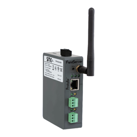
Page 24: Appendix B.6 Physical Dimension Drawing
Appendix B.6 Physical Dimension Drawing Power Port Wi-Fi Antenna Socket R2 Serial Port R1 Serial Port Figure 39: Modbus/BACnet Gateway Part Number GXXX001932 Dimensions Additional Information... -
Page 25: Appendix C. Vendor Information - Navien
Appendix C. Vendor Information – Navien Appendix C.1 NFB-C Single Boiler Modbus BACnet BACnet Point Name RTU Mappings to BACnet/IP and BACnet MS/TP Object Type Object ID Maximum Heat capacity BACnet BACnet Total time of CH operation Point Name Object Type... - Page 26 11002 Sub04 Frozen protection mode 4002 Sub11 Error state 11006 Sub04 Error state 4006 Sub11 Boiler enable status 11007 Sub04 Boiler enable status 4007 Sub11 Boiler pump op Status 11008 Sub04 Boiler pump op Status 4008 Vendor Information – Navien...
- Page 27 18002 Sub25 Frozen protection mode 25002 Sub18 Error state 18006 Sub25 Error state 25006 Sub18 Boiler enable status 18007 Sub25 Boiler enable status 25007 Sub18 Boiler pump op Status 18008 Sub25 Boiler pump op Status 25008 Vendor Information – Navien...
- Page 28 Sub01 Total amount of gas 1014 Cascade Operating units Sub02 Operation Status 2001 Cascade On/Off state Sub02 Main Error code 2002 CC Average Heating capacity Sub02 Current Heat capacity 2004 CC Maximum Heating capacity Sub02 Supply temperature 2005 Vendor Information – Navien...
- Page 29 4014 Sub07 Current amount of gas 7013 Sub05 Operation Status 5001 Sub07 Total amount of gas 7014 Sub05 Main Error code 5002 Sub08 Operation Status 8001 Sub05 Current Heat capacity 5004 Sub08 Main Error code 8002 Vendor Information – Navien...
- Page 30 13011 Sub10 Current amount of gas 10013 Sub13 Total time of CH operation 13012 Sub10 Total amount of gas 10014 Sub13 Current amount of gas 13013 Sub11 Operation Status 11001 Sub13 Total amount of gas 13014 Vendor Information – Navien...
- Page 31 Sub16 Number of CH operation 16011 Sub19 Total time after installation 19010 Sub16 Total time of CH operation 16012 Sub19 Number of CH operation 19011 Sub16 Current amount of gas 16013 Sub19 Total time of CH operation 19012 Vendor Information – Navien...
- Page 32 22008 Sub25 Return temperature 25006 Sub22 Exhaust temperature 22009 Sub25 Maximum Heat capacity 25008 Sub22 Total time after installation 22010 Sub25 Exhaust temperature 25009 Sub22 Number of CH operation 22011 Sub25 Total time after installation 25010 Vendor Information – Navien...
- Page 33 31002 Sub28 Supply temperature 28005 Sub31 Current Heat capacity 31004 Sub28 Return temperature 28006 Sub31 Supply temperature 31005 Sub28 Maximum Heat capacity 28008 Sub31 Return temperature 31006 Sub28 Exhaust temperature 28009 Sub31 Maximum Heat capacity 31008 Vendor Information – Navien...
- Page 34 WWSD temperature setting WWSD On differential setting Boost interval time setting Cascade Initial op units setting CH supply min temperature setting CH supply max temperature setting CH return min temperature setting CH return max temperature setting Vendor Information – Navien...
-
Page 35: Appendix D. Reference
Appendix D. Reference Appendix D.1 Specifications Appendix D.1.1 Compliance with UL Regulations For UL compliance, the following instructions must be met when operating gateway. The units shall be powered by listed LPS or Class 2 power supply ● suited to the expected operating temperature range. The interconnecting power connector and power cable shall: ●... -
Page 36: Appendix E. Limited 2 Year Warranty
Appendix E. Limited 2 Year Warranty Sierra Monitor Corporation warrants its products to be free from defects in workmanship or material under normal use and service for two years after date of shipment. Sierra Monitor Corporation will repair or replace any equipment found to be defective during the warranty period. - Page 37 Memo...
- Page 38 Memo...
- Page 39 Modbus/BACnet Gateway Start-up Guide Part Number GXXX001932 Technical Support Thank you for purchasing the Navien building automation system interface designed to convert boiler performance data to BACnet MS/TP, BACnet/IP and Modbus TCP/IP protocols. For technical support please contact us at 800-519-8794.
Need help?
Do you have a question about the Modbus/BACnet Gateway and is the answer not in the manual?
Questions and answers