Table of Contents
Advertisement
Quick Links
SHENZHEN VDWALL CO., LTD.
www.vdwall.cn en.vdwall.cn
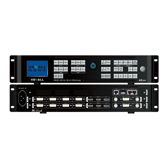
A6000 Series
4K Multi-Window Mosaic Processor
User Manual
V1.0
1
Add: Room 1001, 10th Floor, 4th Building, Fangda-city, Longzhu 4th Road, Nanshan District, 518073 Shenzhen,
China
Tel: +86-755-2675 0210 / 2650 1506 / 2663 6668
QQ:400-0660-628
Technical QQ group:422024594
Advertisement
Table of Contents

Related Manuals for Shenzhen VDWALL A6000 Series

Summary of Contents for Shenzhen VDWALL A6000 Series
- Page 1 SHENZHEN VDWALL CO., LTD. www.vdwall.cn en.vdwall.cn A6000 Series 4K Multi-Window Mosaic Processor User Manual V1.0 Add: Room 1001, 10th Floor, 4th Building, Fangda-city, Longzhu 4th Road, Nanshan District, 518073 Shenzhen, China Tel: +86-755-2675 0210 / 2650 1506 / 2663 6668 QQ:400-0660-628...
-
Page 2: Table Of Contents
A6000Series user manual www.vdwall.cn en.vdwall.cn Contents A6000 Series....................................1 Chapter 1:Safety precautions............................... 2 Chapter 2:Packing list................................3 Chapter 3:Hardware connection............................4 3-1 Rear panel signal port overview........................4 3-2 Port description............................... 4 3-4 Technical specification........................... 6 3-5 Installation dimension.............................8 Chapter 4: Front panel button description........................... 10 4-1 Front panel button sketch map........................10... -
Page 3: Chapter 1:Safety Precautions
A6000Series user manual www.vdwall.cn en.vdwall.cn Chapter 1:Safety precautions Danger ! There is high voltage in the processor, to prevent any unexpected hazard, please do not open the cover of the device,unless you are a maintenance personnel. Warning ! 1) This device shall not encounter water sprinkle or splash, please do not place anything containing water on this device. -
Page 4: Chapter 2:Packing List
A6000Series user manual Chapter 2 : Packing list Chapter 2:Packing list Please unpack the product with care, and then check whether all the following items are included in the package. If anything is found missing, please contact the dealer. Standard accessories The accessories supplied with this product may differ from the following pictures, but they are applicable for the regions where you live (LED sending card is optional accessory) 1.5m DVI cable... -
Page 5: Chapter 3:Hardware Connection
A6000Series user manual Chapter 3:Hardware connection Chapter 3:Hardware connection 3-1 Rear panel signal port overview Picture 3-1 Rear panel signal port ①Video input port ②Video output port ③Communication port 3-2 Port description 1. Video signal input A6000 can assemble maximum 4 video input cards, the series numbers are In-A、In-B、In-C、In-D. In-A and In-B are 2K input cards,In-C and In-D are 4K input cards . - Page 6 A6000Series user manual Chapter 3:Hardware connection Each 4K video input card supports 3 channels of signal input, signal input port description as the following table: Ports Description HDMI 2 channel of HDMI2.0 digital signal input 1 channel of DP1.2 digital signal input 2.
-
Page 7: Technical Specification
A6000Series user manual Chapter 3:Hardware connection 3-3 Hardware connection diagram Picture 3-2 Hardware connection diagram Technical specification Input signal index 4×HDMI 2.0(VESA/CEA-861) 2×DP1.2(VESA) Quantity / type 2×CVBS 2×DVI-I(VESA/CEA-861,support VGA/DVI/HDMI 1.3a) 2×SDI(SDI/HD-SDI/3G-SDI) Composite video system PAL/NTSC Composite video 1V(p_p)/ 75Ω amplitude / Impedance VGA format PC(VESA)... - Page 8 A6000Series user manual Chapter 3:Hardware connection PC(VESA) ≤1920×1200_60Hz DVI /HDMI format HDMI1.3(CEA-861) ≤1080p_60Hz SMPTE259M-C 480i_60Hz SMPTE 292M SDI format 576i_50Hz SMPTE 274M/296M 720p、1080i、1080p SMPTE 424M/425M PC(VESA) HDMI 2.0 ≤4096 x 2160_60Hz (HDCP 2.2) HDMI2.0(CEA-861) DP1.2 DisplayPort1.2(VESA) ≤4096 x 2160_60Hz (HDCP 2.2) CVBS:BNC/ 75Ω...
-
Page 9: Installation Dimension
A6000Series user manual Chapter 3:Hardware connection Installation dimension Picture 3-5a Installation dimension drawing... - Page 10 A6000Series user manual Chapter 3:Hardware connection RS232 connection cable and wire order Note: 1. A is RS232 female connector 2. B is RJ45 connector 3. Accord with emergency decree, The wires must be soft Picture 3-5b RS232 connection cable and wire order...
-
Page 11: Chapter 4: Front Panel Button Description
A6000Series user manual Chapter 4:Front panel button description Chapter 4: Front panel button description Front panel button sketch map Picture 4-1 Front panel button sketch map ①Input card button ②Setup button ③Other function button 1. Input signal selection button Input signal selection button used to select signal source and open PIP, divided into 4 groups. In-A input card button: SDI-1、HDMI-1、CVBS-1、PIP/In-A In-B input card button: SDI-2、HDMI-4、CVBS-2、PIP/In-B In-C input card button: HDMI-2、HDMI-3、DP-1... - Page 12 A6000 series user manual Chapter 5:Basic operation instruction OK: press Knob / OK button, to save parameter : back to previous menu 3. Output Card / Output Port selection button Output Card and Output Ports selection button,used to select output DVI port Out-A/DVI-n、Out-B/DVI-n...
- Page 13 A6000 series user manual Chapter 5:Basic operation instruction display mode saves 4 configuration items and corresponding value: A: image size and position ( including the input and output image ) B: overlay order of multi-layer C: on-off status of window (Win On / Off status) D: signal source of each window 8.
-
Page 14: Chapter 5:User Basic Operation Instruction
A6000 series user manual Chapter 5:Basic operation instruction Chapter 5:User basic operation instruction After processor boot up, A6000 will automatically detect the quantity and configuration information of input and output card. Processor LCD display interface varies from different customized boards assembled. The following is standard display interface of full configuration (4 input boards, 2 output boards) . - Page 15 A6000 series user manual Chapter 5:Basic operation instruction Switch up VGA signal Switch down DVI/HDMI Picture 5-1a DVI-I switch Input card C: press button HDMI-2、HDMI-3、DP-1 to select signal source; Input card D: press button HDMI-5、HDMI-6、DP-2 to select signal source; 2. Input card PIP operation Input card A: press button PIP/In-A to enter or exit PIP.
-
Page 16: Output Card Operation
A6000 series user manual Chapter 5:Basic operation instruction 5-2 Output card operation Under user operation state, output card operation includes: output card display mode selection, output brightness adjustment. 1. Output card display mode recall and mode duplication A6000 multi-window display mode has 16 presets(M0-M15), select M0~M12 by pressing mode button, M13~M15 are backup modes, can't be recalled directly. - Page 17 A6000 series user manual Chapter 5:Basic operation instruction 2. Output card brightness setup Output card brightness adjustment ranges from 0 – 255, “0” represents the lowest brightness level, press Brt+ button to increase, and press Brt- button to decrease, or rotate Knob button to adjust value. In order to guarantee sufficient grayscale, the default brightness value is 128.
- Page 18 A6000 series user manual Chapter 5:Basic operation instruction In-A:HDMI1 PIP:off In-B:CVBS2 PIP:CVBS2 In-C:HDMI2 In-D:DP2 -------------------------------------- Multi Win:Win1->Win2->Win3->Win4 Input Card:In-D In-C In-A In-B Multi Win Mode:M3 Output Mode:M0 Picture 5-3a Output card mode switching 2. Multi-window display mode operation There are 16 preset multi-window display modes, M0 ~ M15, among which M0 ~ M12 is available for direct recall , M13 ~ M15 is used for backup (cannot be recalled directly).
- Page 19 A6000 series user manual Chapter 5:Basic operation instruction 5-4 Other functions operation Except above operations, there are lock button operation, system Info function and other related operations. 1. Lock button operation Under operation state, press Lock button to activate function, other buttons will be invalid, only LAN, RS232, USB control is active, thus to prevent remote control and front panel control conflict.
- Page 20 A6000 series user manual Chapter 5:Basic operation instruction System Info -------------------------------------- Made data: 2017-04 -------------------------------------- Picture 5-4c System info Input - A(HD) -------------------------------------- Version: V1.1.0 MAIN: HDMI-1 Input Signal: 1080p_60Hz PIP: Input Signal: No Input -------------------------------------- Picture 5-4d System info...
- Page 21 A6000 series user manual Chapter 5:Basic operation instruction Multi Win –Win2 -------------------------------------- Version: V1.1.3 Win2: In-C -------------------------------------- Picture 5-4f System info Output - A -------------------------------------- Version: V1.1.3 Resolution: 1920x1080_60Hz -------------------------------------- Picture 5-4g System info System Random Checksum ---------------------------------------- In-A: AF8F0E8E0D8D0C8 AF8F0E8E0D8D0C8 In-B:...
-
Page 22: Chapter 6 User Setup Menu
A6000Series user manual Chapter 6:User setup menu Chapter 6 User setup menu The user setup menu contains 6 main parts, including language setup, video input setup, multi-window setup, output image setup, communication setup and system setup. Setup -------------------------------------- 1. 语言/Language English 2. -
Page 23: Video Input Setup
A6000 series user manual Chapter 6:Basic operation instruction 6-2 Video input setup After system boot up, press Setup into user setup menu, select 2.Video Input by pressing ↑,↓ button, press OK button into this menu, this menu is used to set the parameters of Input Card-A and Input Card-B. - Page 24 A6000 series user manual Chapter 6:Basic operation instruction 2.1.1 Main Setup(In-A) -------------------------------------- 2.1.1.1 Out Width 1920 2.1.1.2 Out H_Start 2.1.1.3 Out Height 1080 2.1.1.4 Out V_Start -------------------------------------- Picture 6-2c Main setup 2.1.2 PIP Setup(In-A) -------------------------------------- 2.1.2.1 Out Width 2.1.2.2 Out H_Start 2.1.2.3 Out Height...
-
Page 25: Multi-Window Setup
A6000 series user manual Chapter 6:Basic operation instruction 3. Resume Data Setup 2.1 Input Card(In-A) -------------------------------------- 2.1.1 Main Setup >> 2.1.2 PIP Setup >> 2.1.3 Color & Brightness, etc. >> 2.1.4 Resume Data OK To Apply -------------------------------------- Write System Data to In-A... - Page 26 A6000 series user manual Chapter 6:Basic operation instruction 1. Multi-window matrix setup 3. Multi-Window ---------------------------------------------------------------------- 3.1 Win2 In-D 3.2 Switching Effect Fade in/out 2S 3.3 Size and Position >> 3.4 Frame >> 3.5 Image Quality >> 3.6 Data Restore Ok To Apply...
- Page 27 A6000 series user manual Chapter 6:Basic operation instruction Setup procedure: Press Setup enter the menu, rotate the Knob button to select switching effect , press OK to save and apply. 3. Size and Position Setup Press Setup button to enter 3. Multi-window menu, press the ↓ key to select the 3.3 Size and Position , then press the Knob key (OK) into the menu.
- Page 28 A6000 series user manual Chapter 6:Basic operation instruction 3.4 Frame Win1 -------------------------------------------- 3.4.1 Frame 3.4.2 Frame Red 3.4.3 Frame Green 3.4.4 Frame Blue 3.4.5 Frame Size Picture 6-3d Image frame setup 5. Image Quality setup Enter 3. Multi-window menu, press ↓ button to select 3.4 Image Quality, press OK into menu. User can set brightness, contrast and color parameters of each window in this menu.
- Page 29 A6000 series user manual Chapter 6:Basic operation instruction 3.5.2. Contrast Default -------------------------------------------- 3.5.2.1 All Win 128 -> 45 3.5.2.2 Win1 3.5.2.3 Win2 3.5.2.4 Win3 3.5.2.5 Win4 -------------------------------------- Picture 6-3g Contrast setting 3.5.3Color Default -------------------------------------------- 3.5.3.1 All Win 128 -> 45 3.5.3.2 Win1...
-
Page 30: Output Image Setup
A6000 series user manual Chapter 6:Basic operation instruction 3.6 Data Restore menu is used to restore system data to the corresponding multi-window card, which is generally used after replacing the multi-window card. Press ↑ , ↓ to select the 3.6 Data Restore menu, press OK to select, press OK again to confirm and apply as prompt . - Page 31 OK to apply, press OK again to confirm and reboot process automatically. The new output resolution will be activated after reboot. Not only the preset output resolutions, A6000 series also support user defined output resolutions. Custom Output Resolution setup: select 4.1 Custom Output Resolution , press OK into the menu, set 4.1.1Custom Width and 4.1.2Custom Height parameters, then select 4.1.3 Press OK to apply, double press...
- Page 32 A6000 series user manual Chapter 6:Basic operation instruction Fast Mosaic Procedures: 1.Press display mode button (M0,M1,M2,M+) to select the display mode; 2. Press Out-A/DVI-n、Out-B/DVI-n to select the connected output card and output port; 3. Firstly set the total width and height of the whole LED screen, secondly set the size and position of the unit screen driven by the corresponding output port.
- Page 33 A6000 series user manual Chapter 6:Basic operation instruction 4.3 Manual Mosaic Out-A/M0/DVI1 -------------------------------------------------- 4.3.1 In Width 3840 3840 4.3.2 In H_Start 4.3.3 In Height 2160 2160 4.3.4 In V_Start 4.3.5 Out Width 1920 1920 4.3.6 Out H_Start 4.3.7 Out Height...
- Page 34 A6000 series user manual Chapter 6:Basic operation instruction 4.4.1 Brightness Default -------------------------------------------------- 4.4.1.1 All DVI 128 -> 45 4.4.1.2 DVI1 4.4.1.3 DVI2 4.4.1.4 DVI3 4.4.1.5 DVI4 -------------------------------------- Picture 6-4g Brightness setting 3.4.2 Contrast Default -------------------------------------------- 3.4.2.1 All DVI 128 -> 45 3.4.2.2 DVI1...
-
Page 35: Communication Setup
A6000 series user manual Chapter 6:Basic operation instruction Data recovery setting 4. Image output(Out-A) 4.1 output resolution 1920x1080_60Hz 4.2 quick mosaic >> 4.3 manual mosaic >> 4.4 Image quality >> 4.5 Data recovery Press OK -------------------------------------- Write data to Out-A Picture 6-4j Image output setting 4.5 Data recovery function is used to restore system data to selected output card,generally used after... - Page 36 A6000 series user manual Chapter 6:Basic operation instruction 5.Communication menu is used to set the processor's network communication parameter. Under this menu, press↓ button to select parameter need adjusted, rotate the Knob button to adjust value, press OK to confirm and save. Press to exit menu.
-
Page 37: Chapter 7: System Maintenance And Related Operation
Chapter 7: System maintenance and related operation A6000 series processor adpot inserting card design. With system data recovery , system random check and verification, as well as the data import and export function, device engineering maintenance is easy and convenient. -
Page 38: Data Recovery
A6000 series user manual Chapter 7:Basic operation instruction The first bit of the checksum value represents the card, if it starts with A, it means the data belongs to A card; If the card encounter communication malfunction or data disorder, the card's checksum value will be different from the system which will be displayed in red. - Page 39 A6000 series user manual Chapter 7:Basic operation instruction 2.1 Input card(In-A) 2.1.1Main screen settings >> 2.1.2 Sprite settings >> 2.1.3 Image quality >> 2.1.4 Data recovery Press OK to use -------------------------------------- Write data to In-A Pigure 7-2a Input card data recovery 3.
-
Page 40: Pc Software Import And Export
A6000 series user manual Chapter 7:Basic operation instruction 7-3 PC software import and export Except data recovery function mentioned above, we can also use the configuration data import and export function to facilitate processor configuration and engineering maintenance. The export function is used to save current processor configuration to PC as a file, including input card and output card configuration data. -
Page 41: Chapter 8:Model Code Description
Chapter 8:Modes code description Chapter 8:Model code description The A6000 series adopt customized inserting card design, maximum 4 input card and 2 output card. Refer to the following model code description of different cards built in. A6 X Y Z...
Need help?
Do you have a question about the A6000 Series and is the answer not in the manual?
Questions and answers