Table of Contents
Advertisement
B
AKULA
9000
User Manual
Geoscanners AB
Note: The information in this User Manuak is based on the latest information at the time of publication. Geoscanners AB® reserves the right to make changes at any
time, without notice to color, specifications, accessories, materials and models. For more information contact the Geoscanners AB Sales Department +46(0)92153020.
©2015 Geoscanners AB, Sweden.
Advertisement
Table of Contents

Related Manuals for Geoscanners AB AKULA 9000B

Summary of Contents for Geoscanners AB AKULA 9000B
- Page 1 Geoscanners AB Note: The information in this User Manuak is based on the latest information at the time of publication. Geoscanners AB® reserves the right to make changes at any time, without notice to color, specifications, accessories, materials and models. For more information contact the Geoscanners AB Sales Department +46(0)92153020.
- Page 2 Thank you for purchasing a Geoscanners AB product The Akula 9000B is a high performance, lower band, ground penetrating radar. It is compatible with all Geoscanners AB antennas with center frequencies up to 600MHz and has an analogue bandwidth in excess of 1200MHz.
-
Page 3: Rev:en05130513
Keep the unit dry and the fan holes free for air blowing out. The Akula 9000B control unit is IP54 rated meaning that the unit is protected against sprays from all directions and that limited ingress is permitted. However, the control unit will not function properly if large amount of water comes into the unit. - Page 4 Led Acid Battery in its own pouch 7.5A/h • Led Acid Battery charger • Generic Netbook with GAS™ control software and GPRSoft™ standard edition installed • Geoscanners AB software solutions disk (contains GAS™ and GPRSoft™ distribution packages) • Suitcase for the control unit • Instruction Manual •...
-
Page 5: Table Of Contents
AKULA 9000B USER MANUAL REV:EN05130513-03 Table of Contents SECTION 1 Before you start 1.1 Recharging the Battery 1.2 Connecting The Antenna 1.3 Connecting the Battery and Control PC SECTION 2 Basic Setup 2.1 Starting GAS™ and Running Setup SECTION 3 Full Unit Setup 3.1 Main Window and Control... -
Page 6: Section 1 Before You Start
SECTION 1 Before You Start This section explains a few preliminary steps and the basic operation of the Akula 9000B ground penetrating radar control unit. -
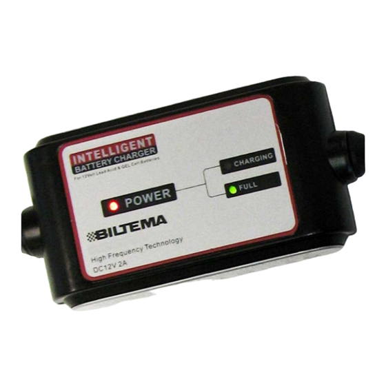
Page 7: Recharging The Battery
You should always use the charger* provided in the package to charge your units battery. • in case of malfunction of the charger or battery life end, please contact Geoscanners AB for advice on selecting the appropriate substitute. 2. Connect the battery to the charger •... -
Page 8: Connecting The Antenna
In this situation the internal survey wheel cable is not in use and should be disabled in the control software. • Geoscanners AB survey wheel encoders are protected against double connections. However, third party survey wheel encoders might not. Do not connect two survey wheel encoders simultaneously if you are not sure. -
Page 9: Connecting The Battery And Control Pc
• Your Akula 9000B kit is supplied with a preconfigured PC so it will not need to install any additional drivers for the GPR control unit. If you are using your own PC then installing the drivers might be required. -
Page 10: Section 2 Basic Setup
SECTION 2 Basic Setup This section explains the basic setup of the unit and how to start recording a file in time mode. -
Page 11: Starting Gas™ And Running Setup
/ SECTION 2 AKULA 9000B USER MANUAL REV:EN05130513-03 Starting GAS™ and Running Setup 1. Start The Collection Software • Start the collection software by double clicking the icon on your desktop or by selecting the software from the Windows start menu. - Page 12 Your data is now available in the default directory. See Global Settings for more details. 6. Getting Help • At Geoscanners AB we are proud to provide the best customer support in the industry. • To allow us to be able to help you efficiently please always provide the model number, serial number and firmware revision of your unit.
-
Page 13: Section 3 Full Unit Setup
SECTION 3 Full Unit Setup This section gives a detailed review of all the setup functions of the control software, and how they affect the collection of the data. -
Page 14: Main Window And Control
/ SECTION 3 AKULA 9000B USER MANUAL REV:EN05130513-03 Main Window and Control The control unit receives all the necessary information about the working parameters via the communications cable, this can be USB or Ethernet. Upon power up the power LED in your control unit will flash continuously indicating that it hasn’t been able to establish a communication link with the control software GAS™... - Page 15 / SECTION 3 AKULA 9000B USER MANUAL REV:EN05130513-03 10. Control Unit Model: when GAS™ connect with your control unit the very first thing it will attempt is to retrieve the model number, the serial number and the radar status. When all this information has been successfully retrieved the control unit model number appears in this place.
-
Page 16: Global Settings Dialogue Window
/ SECTION 3 AKULA 9000B USER MANUAL REV:EN05130513-03 Global Settings Dialogue Window The global settings window is the main tool of GAS™ to control the way and feel of the software plus the required external devices. To open the global settings dialogue window press the icon in the main toolbar or press Alt+S on your keyboard. -
Page 17: Gps Usage
“Beep” box in the Global Settings window. Since the Akula 9000B ground penetrating radar control unit can be used to a wide variety of antennas from different manufacturers then a way of controlling the polarity of the transmitted pulse of the incoming data is mandatory. -
Page 18: Setup Panel
/ SECTION 3 AKULA 9000B USER MANUAL REV:EN05130513-03 Setup Panel The setup panel is always available on the right side of the screen when the control software is in setup mode. By default the “Scan” tab is open and the “Gain”, “Filters”... - Page 19 / SECTION 3 AKULA 9000B USER MANUAL REV:EN05130513-03 3.4.1 Scan Box Scan Range – The scan range box has a field that can be increased or decreased using the up and down arrows on the right of it. GAS™ automatically recognizes what control unit model is attached to the control PC. Since GAS™...
- Page 20 / SECTION 3 AKULA 9000B USER MANUAL REV:EN05130513-03 3.4.2 Gain Box The electromagnetic waves suffer heavy attenuation as it penetrates the materials and the reflections from the objects in them are increasingly weaker with the increase of the penetration depth. This is the reason why we need to apply a non-linear gain function to the acquired data.
- Page 21 / SECTION 3 AKULA 9000B USER MANUAL REV:EN05130513-03 3.4.3 Filters Box The antennas attached to your control unit are broad band devices that transmit electromagnetic waves covering substantial parts of the spectrum. This is one of the reasons we can use ground penetrating radar to investigate the underground and materials.
- Page 22 U-Explorer units or to use one of the approved survey wheel encoders available from Geoscanners AB. The “external” radio button selects the input on your antenna and the survey wheel data is then coming via the control cable supplied with your unit.
-
Page 23: Visual Enhancements
/ SECTION 3 AKULA 9000B USER MANUAL REV:EN05130513-03 Visual Enhancements There are other tools available for the field surveyor that help the visualization of the results and interpretation of the data without affecting the collected data. One of these tools is the contrast slider control that you can find at the bottom of the screen. -
Page 24: Gps Function
GPS Function Geoscanners AB file format, the GSF format is unique in a way that all the necessary information is stored within one file. There is no need to have several files to accurately reconstruct the acquired survey. The GPS coordinates are also embedded in the GSF file and the latitude, longitude and altitude are stored for each individual collected trace. -
Page 25: Macro Functions
/ SECTION 3 AKULA 9000B USER MANUAL REV:EN05130513-03 Macro Functions There are many occasions when the type of survey and the soil conditions are very similar and therefore the settings to use are also very similar. For this kind of surveys it is very convenient to have an easy way to load previous configurations, this is what macros are all about. -
Page 26: Section 4 Record Mode
SECTION 4 Record Mode This section covers the record mode, hyperbola fitting tool and depth calibration of the unit. -
Page 27: Record Mode
/ SECTION 4 AKULA 9000B USER MANUAL REV:EN05130513-03 Record Mode It is time to enter the record mode when all the parameters for the data acquisition have been satisfactorily set during setup mode. This could be done by pressing the record mode icon in the main toolbar or by pressing Ctrl+D on your keyboard. -
Page 28: Adding Notes To Profiles
/ SECTION 4 AKULA 9000B USER MANUAL REV:EN05130513-03 Adding Notes to Profiles While performing the survey all possible ideas can come to mind, but in a busy day these can be overwhelming and sometimes we find ourselves trying to remember what is it that we had in mind while recording this particular file. -
Page 29: Record Mode In Distance Mode
/ SECTION 4 AKULA 9000B USER MANUAL REV:EN05130513-03 Record Mode in Distance Mode If you have a survey wheel attached to your control unit or antenna and precise measurements are required then recording the data in distance mode is the only way to go. Select the proper radio button in the “scan rate” section of the “scan box”... -
Page 30: Record Mode In One Shot Mode
/ SECTION 4 AKULA 9000B USER MANUAL REV:EN05130513-03 Record Mode in One Shot Mode In geological or archeological applications sometimes it is necessary to make surveys in specific locations or points if you prefer. For this kind of surveys we have implemented the one shot mode which basically will collect one trace at the time when you press the one shot button. - Page 31 / SECTION 4 AKULA 9000B USER MANUAL REV:EN05130513-03 The signal position or offset is extremely important to be set correctly, the algorithm to calculate the relative dielectric permittivity assumes that the signal propagates always through the media and that a constant RDP is present. This latest...
-
Page 32: Depth Calibrating Tool
/ SECTION 4 AKULA 9000B USER MANUAL REV:EN05130513-03 Depth Calibrating Tool Sometimes we do not have any targets that could produce a hyperbola, but have some layer at a known depth from the surface. The hyperbola tool in these cases is of little use and we need to use something else. We have a depth calibration tool which will allow the user to pinpoint a target and enter the known depth to it. -
Page 33: Section 5 Playback Mode
SECTION 5 Playback Mode This section explain how to use the playback mode available in GAS™... -
Page 34: Playback Mode
/ SECTION 5 AKULA 9000B USER MANUAL REV:EN05130513-03 Playback Mode Although we supply all our ground penetrating radar units with a free version of GPRSoft™ standard, we have also equipped GAS™ with a basic playback function to display recently stored files and viewing them in the same environment they were collected. -
Page 35: Appendices
APPENDICES Playback Mode... -
Page 36: Appendix A - Keyboard Shortcuts
/ APPENDICES AKULA 9000B USER MANUAL REV:EN05130513-03 Appendix A – Keyboard shortcuts List of keyboard shortcuts used in GAS™ MODE SHORT-CUT DESCRIPTION Setup Alt+S Opens the general settings dialogue box Setup, Record Alt+G Connects to a GPS receiver on the... -
Page 37: Appendix B - Specifications
/ APPENDICES AKULA 9000B USER MANUAL REV:EN05130513-03 Appendix B - Specifications Technical Specifications of the AKULA 9000B Survey Range 32 to 1021ns in 1ns steps Pulse Repetition Frequency, PRF 200kHz Scan rate 1 to 100 scans/second Resolution 125ps to 1ns Offset +/- 128ns in 0.5ns steps... -
Page 38: Appendix C - Common Materials Rdp
/ APPENDICES AKULA 9000B USER MANUAL REV:EN05130513-03 Appendix C – Common materials RDP Relative Dielectric Permittivity for Common Materials at 100MHz MATERIAL VELOCITY (mm/ns) ATTENUATION dB/m 299.7 Asphalt Dry 2 – 4 212 - 150 2 – 15 Asphalt Wet 6 –...
Need help?
Do you have a question about the AKULA 9000B and is the answer not in the manual?
Questions and answers