Table of Contents
Advertisement
Hangzhou Poer Tech., Co., Ltd
Add.: 19th. Floor, Xingtu Building, No.451
Wulianwang Street, Binjiang Zone, Hangzhou
City, 310051 Zhejiang Pro., CHN.
www.poersmart.com
Tel.: +86-571-85800292
Fax: +86-571-28190666
E-mail: support@poersmart.com
smart controls
User Manual
Wireless Programmable
Room Thermostat
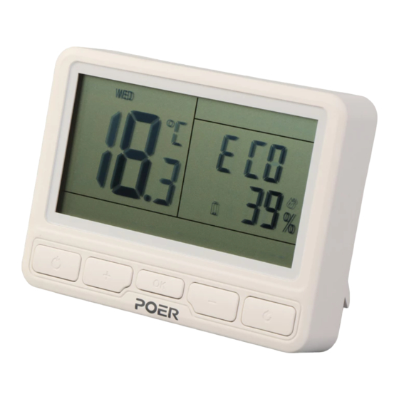
Model No.: PTC10 / PTR10
Scan for App
Power to control your heating
Anytime, Anywhere
Advertisement
Table of Contents


Need help?
Do you have a question about the PTC10 and is the answer not in the manual?
Questions and answers
Здравствуйте! Вышлите пожалуйста таблицу с расшифровкой настроек пользователя на русском языке. (poer ptc10 )
Добавление: В настройках на моем термостате 20пунктов
Добавление: В настройках моего термостата 20 пунктов
Добавление