Table of Contents
Advertisement
Quick Links
EQUIPMENT
. . . . . . . . . .
SELECTION
PFI--1
. . . . . . . . . . . . . . . . . . . . . . .
Balancer
. . . . . . . . . . . . . . . . . . . .
JARVIS
6223015::.
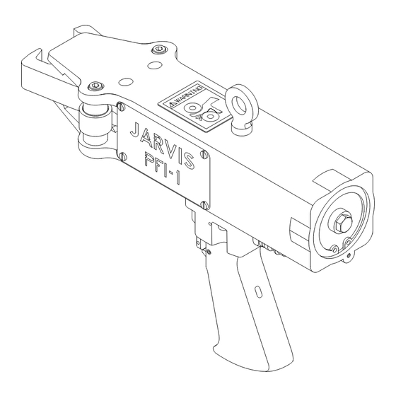
PFI- -1
PICKING FINGER INSTALLER
Ordering No.
4311002
1350147
®
TABLE OF
CONTENTS
. . . . . . . . . . . . . . . . . . . . . . . . .
• Safety Messages to Employer and Safety
Director
. . . . . . . . . . . . . . . . . . . . . . . . .
• Safety Messages to Operators
Maintenance and Cleanup Personnel 3
• Parts Diagram and List
• Specifications
. . . . . . . . . . . . . . . . . . . .
• Installation Instructions
• Operation Instructions
• Maintenance Instructions
PRODUCTS CORPORATION
33 ANDERSON ROAD, MIDDLETOWN, CONNECTICUT 06457--4926
UNITED STATES OF AMERICA E--Mail sales@jarvisproducts.com
TEL. 860--347--7271
FAX. 860--347--6978
Page
2
. . . . . . . . . . . .
4
5
. . . . . . . . . . . .
5
. . . . . . . . . . . . .
5
. . . . . . . . . .
6
WWW.jarvisproducts.com
Advertisement
Table of Contents

Subscribe to Our Youtube Channel
Related Manuals for Jarvis PFI-1


Summary of Contents for Jarvis PFI-1
- Page 1 • Operation Instructions ... . . • Maintenance Instructions ..JARVIS PRODUCTS CORPORATION ® 33 ANDERSON ROAD, MIDDLETOWN, CONNECTICUT 06457--4926 UNITED STATES OF AMERICA E--Mail sales@jarvisproducts.com TEL.
-
Page 2: Pfi--1
8. Avoid injury. Do not permit the tool to be misused. 9. If you resell or distribute a Jarvis product, you must provide the purchaser with the appropriate safety sheets and tool brochure. Additional copies of safety sheets and tool brochures will be provided upon request. -
Page 3: Safety Messages To Operators Maintenance And Cleanup Personnel
6. Never depress the trigger unless you want to use the tool. 7. Never make modifications or alterations to the tool. Replace any missing or illegible labels. JARVIS PRODUCTS CORPORATION ® 33 ANDERSON ROAD, MIDDLETOWN, CONNECTICUT 06457--4926 UNITED STATES OF AMERICA E--Mail sales@jarvisproducts.com... -
Page 4: Parts Diagram And List
Insertion Tool Assembly If any part of trigger and valve assembly needs replacing, the whole assembly must be replaced. A special tool, Jarvis part number 8330024, is required for trigger valve sleeve removal and installation. ITEM PART NO. PART NAME 1323011** Hose Assy (incls. -
Page 5: Balancer
Operating Pressure 90 psi 6.2 bar to the full mark. (Use Jarvis Air Mist Lubrica- Air Consumption tor Oil; if using a conventional air mist lubrica- Per Cycle at 90 psi 0.091 ft... -
Page 6: Maintenance Instructions
ING ANY MAINTENANCE OR REPAIRS. bottom holes of frame and cylinder housing Refer to Figure A on page 4 for referenced items. (item 17). JARVIS PRODUCTS CORPORATION ® 33 ANDERSON ROAD, MIDDLETOWN, CONNECTICUT 06457--4926 UNITED STATES OF AMERICA E--Mail sales@jarvisproducts.com 6223015::. - Page 7 DISSIPATE STORED ENERGY FROM CYLINDER HOUSING BEFORE PERFORMING ANY MAINTE- 7.7 Clean and inspect all parts for wear and replace them if necessary. NANCE OR REPAIRS. JARVIS PRODUCTS CORPORATION ® 33 ANDERSON ROAD, MIDDLETOWN, CONNECTICUT 06457--4926 UNITED STATES OF AMERICA E--Mail sales@jarvisproducts.com 6223015:.
- Page 8 Do not mix old and new parts. 9.5 Remove U- -cup seal (item 20) from inside the 12.4 Apply a light coat of of Jarvis 1315 White front end of frame and cylinder housing (item Grease to trigger and trigger valve sleeve before 17).
Need help?
Do you have a question about the PFI-1 and is the answer not in the manual?
Questions and answers