Table of Contents
Advertisement
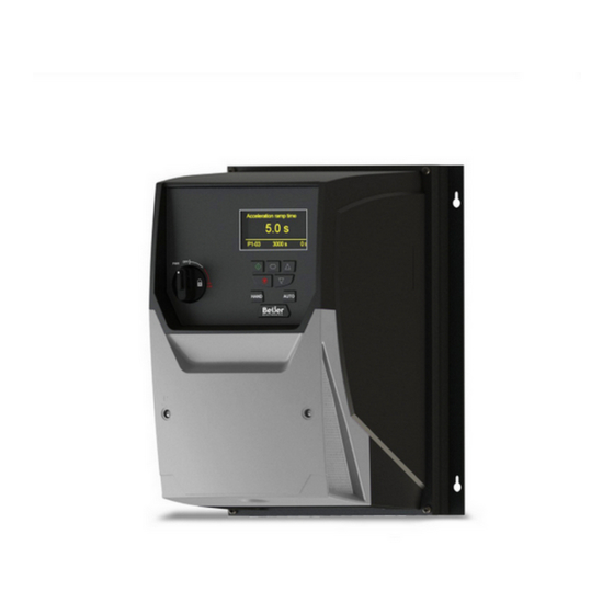
Beijer Electronics Frequency Inverter BFI-H3
1 Start-up document
This document is a short start-up guide describing basic functionality of the drive BFI-H3,
firmware 2.50, manufactured from August 2019. Detailed explanations are to be read in
User Manual BFI-H3. This manual is attached with the drive itself but also possible to
download from
beijerelektronik.com.tr
2 Important Safety Information
Please read the IMPORTANT SAFETY INFORMATION below, and all Warning and Caution
information elsewhere.
Danger : Indicates a risk of electric shock, which, if not
avoided, could result in damage to the equipment and
possible injury or death.
This variable speed drive product is intended for professional incorporation into complete equipment or systems as part of a fixed installation. If installed
incorrectly it may present a safety hazard. The BFI uses high voltages and currents, carries a high level of stored electrical energy, and is used to control
mechanical plant that may cause injury. Close attention is required to system design and electrical installation to avoid hazards in either normal operation
or in the event of equipment malfunction. Only qualified electricians are allowed to install and maintain this product.
System design, installation, commissioning and maintenance must be carried out only by personnel who have the necessary training and experience.
They must carefully read this safety information and the instructions in this Guide and follow all information regarding transport, storage, installation and
use of the BFI, including the specified environmental limitations.
Do not perform any flash test or voltage withstand test on the BFI. Any electrical measurements required should be carried out with BFI disconnected.
Electric shock hazard! Disconnect and ISOLATE the BFI before attempting any work on it. High voltages are present at the terminals and within the
drive for up to 10 minutes after disconnection of the electrical supply. Always ensure by using a suitable multimeter that no voltage is present on any
drive power terminals prior to commencing any work.
Where supply to the drive is through a plug and socket connector, do not disconnect until 10 minutes have elapsed after turning off the supply.
Ensure correct earthing connections. The earth cable must be sufficient to carry the maximum supply fault current which normally will be limited by the
fuses or MCB. Suitably rated fuses or MCB should be fitted in the mains supply to the drive, according to any local legislation or codes.
Do not carry out any work on the drive control cables whilst power is applied to the drive or to the external control circuits.
Within the European Union, all machinery in which this product is used must comply with Directive 98/37/EC, Safety of Machinery. In particular, the
machine manufacturer is responsible for providing a main switch and ensuring the electrical equipment complies with EN60204-1.
The level of integrity offered by the BFI control input functions – for example stop/start, forward/reverse and maximum speed is not sufficient for use in
safety-critical applications without independent channels of protection. All applications where malfunction could cause injury or loss of life must be
subject to a risk assessment and further protection provided where needed.
The driven motor can start at power up if the enable input signal is present.
The STOP function does not remove potentially lethal high voltages. ISOLATE the drive and wait 10 minutes before starting any work on it. Never carry
out any work on the Drive, Motor or Motor cable whilst the input power is still applied.
The BFI can be programmed to operate the driven motor at speeds above or below the speed achieved when connecting the motor directly to the mains
supply. Obtain confirmation from the manufacturers of the motor and the driven machine about suitability for operation over the intended speed range
prior to machine start up.
Do not activate the automatic fault reset function on any systems whereby this may cause a potentially dangerous situation.
The BFI has an Ingress Protection rating of IP20, IP55 or IP66 depending on the model. IP20 units must be installed in a suitable enclosure.
When mounting the drive, ensure that sufficient cooling is provided. Do not carry out drilling operations with the drive in place, dust and swarf from
drilling may lead to damage. BFI are intended for indoor use only.
The entry of conductive or flammable foreign bodies should be prevented. Flammable material should not be placed close to the drive
Relative humidity must be less than 95% (non-condensing).
Ensure that the supply voltage, frequency and no. of phases (1 or 3 phase) correspond to the rating of the BFI as delivered.
Never connect the mains power supply to the Output terminals U, V, W.
Do not install any type of automatic switchgear between the drive and the motor
Wherever control cabling is close to power cabling, maintain a minimum separation of 100 mm and arrange crossings at 90 degrees
Ensure that all terminals are tightened to the appropriate torque setting
Do not attempt to carry out any repair of the BFI. In the case of suspected fault or malfunction, contact Beijer Electronics office for further assistance.
Beijer Electronics a company in the Beijer Electronics Group
Parent Company (Reg. office)
Beijer Electronics AB
P.O. Box 426
SE-201 24 MALMÖ, SWEDEN
Telephone +46 40 35 86 00
Fax +46 40 93 23 01
Visiting address: Stora Varvsgatan 13a, Malmö
www.beijerelectronics.se
or
.dk
or
.no
or
.de
or
Danger : Indicates a potentially hazardous
situation other than electrical, which if not
avoided, could result in damage to property.
Subsidiaries
Norway, Drammen: Beijer Electronics AS, +47 32 24 30 00
Denmark, Copenhagen: Beijer Electronics A/S,
Germany, Nürtingen: Beijer Electronics GmbH, +49 7022 9660 0
UK, Castle Donington: Beijer Electronics Products, +44 (0)845519 5430
France, Champlan: Beijer Electronics +33 (0)1 69 10 22 42
Turkey Istanbul: Beijer Electronics ve Ticaret A.s 0090 216 366 32 0200
KI00363B 2019-09
.com
or
.tw
or
.co.uk/
Page 1 (29)
+45 75 76 66
or
Advertisement
Table of Contents

Related Manuals for BeiJer BFI-H3

Summary of Contents for BeiJer BFI-H3
-
Page 1: Start-Up Document
Ensure that all terminals are tightened to the appropriate torque setting Do not attempt to carry out any repair of the BFI. In the case of suspected fault or malfunction, contact Beijer Electronics office for further assistance. Page 1 (29) Beijer Electronics ... -
Page 2: Table Of Contents
The material may only be used with products or software supplied by Beijer Electronics. Beijer Electronics assumes no responsibility for any defects in the material, or for any consequences that might arise from the use of the material. -
Page 3: Installation
IP55/66 is allowed to be mounted outdoors but must be protected from sunlight and it also recommended having a roof to avoid snow directly on the drive. See User Manual BFI-H3 for more details. Drive IP-class... -
Page 4: Physical Dimensions Ip20
Beijer Electronics Frequency Inverter BFI-H3 KI00363B 2019-09 IP66 drives are fitted with 3 knockout holes for cable inlet and outlet. If more than 3 cables are to enter the drive it is possible to have two or more cables going through one gland. This is to ensure IP66. -
Page 5: Physical Dimensions Ip55
Beijer Electronics Frequency Inverter BFI-H3 KI00363B 2019-09 4.3 Physical dimensions IP55 ØI ØJ BFI-H3-IP55 Weight Drive [mm] Height [mm] [mm] Depth Width [mm] [mm] [mm] [kg] size 3 x 230 V 3 x 400 V [mm] [mm] [mm] 0300 – 0460 0300 –... -
Page 6: Fuses, Cable Dimensions And Power Loses
The rise time and peak voltage can affect the service life of the motor. Beijer recommend using an output choke for motor cable lengths of 50m or more to ensure good motor service life. -
Page 7: Derating Information
Beijer Electronics Frequency Inverter BFI-H3 KI00363B 2019-09 4.5 Derating Information Derating of the drive maximum continuous output current capacity is require when: Operating at ambient temperature in excess of 40°C/104°F (IP55 & IP66) or 50°C / 122°F (IP20). Operating at Altitude in excess of 1000m/ 3281 ft. -
Page 8: Overview Of Power Supply, Grounding And Motor Cable
Beijer Electronics Frequency Inverter BFI-H3 KI00363B 2019-09 4.6 Overview of power supply, grounding and motor cable Drive is to be connected with ground/PE by separate grounding wire. 3-phase power supply should be connected to L1, L2 and L3. -
Page 9: Safe Torque Off, Sto
Beijer Electronics Frequency Inverter BFI-H3 KI00363B 2019-09 4.7 Safe Torque Off, STO BFI-H3 has two digital inputs for Safe Torque Off. These two inputs must be correct connected otherwise the Drive will not run andInhibit will be shown on the display. ... -
Page 10: Basic Parameter Setting
Beijer Electronics Frequency Inverter BFI-H3 KI00363B 2019-09 5 Basic Parameter setting The basic parameter setting that always is to be checked or modified is listed below: Para- Name Default To be set Function meter settng P1-01 Maximum Frequency 50 Hz Max freq. -
Page 11: Digital Start In Two Directions And One Preset Or Analog Setpoint
Beijer Electronics Frequency Inverter BFI-H3 KI00363B 2019-09 Para- Name Default To be Function meter settng P1-13 Digital Inputs Function Must be put to 1 Can be set between P1-02(Minimum speed) to P1-01 setting (Maximum speed) P2-01 PresetSpeed1 5 Hz Type of 0: 0 to 10 VDC;... -
Page 12: Digital Start Signal In Two Directions And 8 Fixed Preset Speeds
Beijer Electronics Frequency Inverter BFI-H3 KI00363B 2019-09 5.3 Digital start signal in two directions and 8 fixed Preset speeds Start in two direction and up to 8 fixed speeds. If only 4 fixed speeds are to be used, AIN2 terminal 10, can be excluded. -
Page 13: Alarm Reset
Beijer Electronics Frequency Inverter BFI-H3 KI00363B 2019-09 5.4 Alarm reset Alarm reset is factory set dedicated terminal 2, DIN1. Drive is reseted by positive edge on terminal 2. Observe that terminal 2 also can be Start forward and drive might start if Alarm reset is too long or not turned off. -
Page 14: Fieldbus Control Settings
Beijer Electronics Frequency Inverter BFI-H3 KI00363B 2019-09 5.7 Fieldbus control settings The drive can be controlled by fieldbus or Ethernet. Following settings must be done: P1-12=4, Start/stop/frequency setpoint command by bus P1-14=201, make access to parameters in group 5 mentioned below Terminal 2 must be connected to 24 V and safety inputs(STO+/STO-) correctly connected. -
Page 15: Ptc-Thermistor
A motor thermistor or thermistor contact can be connected to analog input 2, terminal 10. Set P1-13 to 5 or 10, make sure functionality for other inputs follows your specification. If not, adjust functionality manually in parameter group 9. Contact Beijer Electronics for further assistance. -
Page 16: Control From A Modbus Rtu Master
RJTRM- Nexto Express CAB 114 Patchcable Cat 6 Settings in BFI-H3 are speed setting is 115 200 bit/sec, 8 data bits, 1 stop bit, No Parity. Hardware Function Comment CAB 114 Shielded cable with one RJ45 and 3 wires marked Cable length 3 m. -
Page 17: Vector Control
KI00363B 2019-09 5.11 Vector control BFI-H3 is delivered with vector control for a standard induction motor activated. Standard values for a motor with same power rating as the drive is being used. Following parameters must be set properly: - P1-14: Parameter access code, set to 201... -
Page 18: Pid-Control
Beijer Electronics Frequency Inverter BFI-H3 KI00363B 2019-09 5.12 PID-control +24 VDC DIN1: Start signal Status Action DIN2: PID/Preset Speed 1 DIN1 DIN2 P1-12=3 No output from drive 0-10V / 4-20mA AIN2: PID-feedback Run with PID-control Run with Preset speed +10 VDC... - Page 19 Drive can be started with speed in P2-07 without PID active. When time from Boost function at start start in P6-11 has elapsed the drive enters automaticall PID-control. P6-11 0 sec If PID-control is to be performed by serial, Fieldbus or Ethernet, contact Beijer Electronics. 19 (29) www.beijer.se www.beijer.no www.beijer.dk www.beijerelectronics.de www.beijerelectronics.com www.beijerelektronik.com.tr...
-
Page 20: Bfi-Smartstick
Beijer Electronics Frequency Inverter BFI-H3 KI00363B 2019-09 5.13 BFI-Smartstick Communication between BFI Drive and PC-software BFI-Tools or app BFI-Tools Mobile is done by Bluetooth through BFI-Smartstick. Bluetooth is not built into BFI but in BFI-Smartstick, see picture below. BFI-Smartstick is connected to BFI through it’s RJ45 connector. BFI-Smartstick also has a memory for parameter settings that can be read or written by it’s buttons. -
Page 21: Keypad
Beijer Electronics Frequency Inverter BFI-H3 KI00363B 2019-09 6 Keypad The drive is configured and its operation monitored via the keypad and display. Main Displayed Parameter Control Keypad Shows which of the selectable Provides access to the drive parameters is currently being... -
Page 22: Accessing And Changing Parameter Values - Oled Keypad
Beijer Electronics Frequency Inverter BFI-H3 KI00363B 2019-09 6.2 Accessing and Changing Parameter Values – OLED Keypad Hold navigate button in Use up and down keys to Presss / release navigate Use up and down keys to for >1 sec scroll to required button when required edit parameter value. -
Page 23: Changing The Language On The Oled Display - Oled Keypad
Beijer Electronics Frequency Inverter BFI-H3 KI00363B 2019-09 6.4 Changing the Language on the OLED Display – OLED Keypad Hold down the Start and Use the Up and Down to Press the Navigate button Up keys for >1s select a language. -
Page 24: Keypad Short Cuts
Beijer Electronics Frequency Inverter BFI-H3 KI00363B 2019-09 6.6 Keypad Short cuts Function Display Shows… Display Shows… Motor rated voltage Preset Speed 1 Fast Selection of P1-07 P2-01 Parameter Groups Note : Parameter Group 400V 50.0Hz Access must be enabled... -
Page 25: Monitoring From Keypad
Beijer Electronics Frequency Inverter BFI-H3 KI00363B 2019-09 6.7 Monitoring from Keypad Parameter group 0 contain variables to be monitored as table below: Description Display range Explanation P0-01 1st Analog Input Value -100 % to 100% 100% = max input voltage... -
Page 26: General Specification
Beijer Electronics Frequency Inverter BFI-H3 KI00363B 2019-09 General specification BFI-H3 Over Current 125% of rated current for 2,0 s; 110 % for 1 min Output Voltage 3-fas, 0 V to Supply voltage Output Frequency 0 – 500 Hz Input Voltage 1-phase, 200 –... -
Page 27: Warning And Alarm Codes
Beijer Electronics Frequency Inverter BFI-H3 KI00363B 2019-09 8 Warning and Alarm codes Fault Code No. OLED Message Description Corrective Action inhibi Inhibit Safety ingångarna är inte aktiverade. StoP Stop No Fault Displayed in P0-13 if no faults are recorded in the log... - Page 28 Drive output fault. Refer to your Beijer office. Sto-F 29 Internal STO Error Hardware Circuit Error Hardware STO Input Circuit Fault. Refer to your Beijer office. 40 Autotune fail 1 Measured motor stator resistance varies between phases. Check the AtF-01...
- Page 29 Beijer Electronics Frequency Inverter BFI-H3 KI00363B 2019-09 29 (29) www.beijer.se www.beijer.no www.beijer.dk www.beijerelectronics.de www.beijerelectronics.com www.beijerelektronik.com.tr...
Need help?
Do you have a question about the BFI-H3 and is the answer not in the manual?
Questions and answers