
Subscribe to Our Youtube Channel
Related Manuals for Suitmate Swimsuit Water Extractor


Summary of Contents for Suitmate Swimsuit Water Extractor
- Page 1 WWW.RESTROOMDIRECT.COM 704 • 937• 2673 129 Oakpark Dr., Unit A, Mooresville, NC 28115 Manual 115V/60Hz...
- Page 2 WWW.RESTROOMDIRECT.COM 704 • 937• 2673 129 Oakpark Dr., Unit A, Mooresville, NC 28115...
-
Page 3: Table Of Contents
SUITMATE Maintenance Instructions ..............13 ® SUITMATE Troubleshooting ..................15 ® Remove / Replace Mechanical Assemblies ............17 Remove SUITMATE from the Wall Mount Bracket ...17 ® Reinstall SUITMATE to the Wall Mount Bracket ....18 ® Top and Sub Top Assemblies ..........19 Lid ..................23 Riser Cable Assembly ............25... - Page 4 WWW.RESTROOMDIRECT.COM 704 • 937• 2673 129 Oakpark Dr., Unit A, Mooresville, NC 28115 April 13, 2009 115-V 20-Amp 60-Hz Self-Timed Unit...
-
Page 5: Introduction
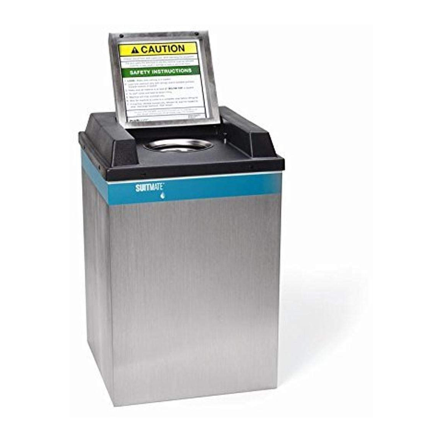
129 Oakpark Dr., Unit A, Mooresville, NC 28115 INTRODUCTION The SUITMATE unit is a high-speed swimsuit water extractor. It is powered by a 1/3 horsepower, 115-V / 60- ® Hz full grounded and fault protected electric motor. The SUITMATE unit weighs approximately ®... -
Page 6: Installation Instructions
PROPER LOCATION FOR THE SUITMATE UNIT ® Following is a list of factors to consider in determining a location for the SUITMATE unit. ® 1) The unit should be located in an area that is near where people remove and rinse out their swimsuits. - Page 7 Remove the SUITMATE unit from its shipping box. Remove and discard the packaging material that is ® protecting the SUITMATE unit. The upper back lip of the SUITMATE unit should be lowered down and ® ® centered on the Wall Mount Bracket. After the unit is centered, push down on the back of the unit to make certain that it is securely wedged onto the bracket.
- Page 8 Note: Strictly follow all applicable local electrical codes and regulations. The SUITMATE® unit is equipped with a ground fault circuit interrupter (GFCI), that is designed to be connected to a 115-V 20-Amp 60-Hz dedicated circuit that is protected by a fuse or circuit breaker of the correct (20 Amp Maximum) size.
- Page 9 Remove the cover of the weatherproof Junction Box, which contains the GFCI, and remove the GFCI mounting screws. The circuit ground conductor must be connected to the green grounding screw located on the GFCI. If no ground is available on the circuit utilized, you must provide a proper ground for the SUITMATE ®...
-
Page 10: Testing And Operation
704 • 937• 2673 129 Oakpark Dr., Unit A, Mooresville, NC 28115 TESTING AND OPERATION After the mounting and all connections are complete, test the SUITMATE unit as follows: ® 1) Make certain all packaging material is removed from the unit including material around the Motor. - Page 11 1) When taking the Exchange unit out of the carton, be careful not to damage the carton as it will be needed to return the defective unit. 2) Hang the Exchange unit on the Wall Mount Bracket by lowering the upper lip of the SUITMATE unit case ®...
- Page 12 704 • 937• 2673 129 Oakpark Dr., Unit A, Mooresville, NC 28115 TESTING OF THE EXCHANGE UNIT After the mounting and completion of all connections, test the SUITMATE unit as follows: ® 1) Make certain all packaging material is removed from the unit including material around the Motor.
- Page 13 115-V 20-Amp 60-Hz Self-Timed Unit This diagram is for reference only! It is not to be used as the sole reference WARNING! for installation of the SUITMATE unit. The installation instructions beginning ® on page 4 must be followed explicitly! Centerline of 3 8 "...
- Page 14 WWW.RESTROOMDIRECT.COM 704 • 937• 2673 129 Oakpark Dr., Unit A, Mooresville, NC 28115 MAINTENANCE SIGN OFF LOG Weekly Physical Inspection Date Performed By: Date Performed By: Date Performed By: Date Performed By: Date Performed By: Hygenic Cleaning Date Performed By: Date Performed By: Date...
-
Page 15: Maintenance Instructions
The spun towel can then be used to wipe down the Basket, the Black Plastic Top, the Lid, and the sides of the unit. d. Re-wipe the surfaces (Basket, Black Plastic Top, Lid, and the exterior of the unit) with a fresh towel and clean water. Never use flammable solvents in or on the SUITMATE unit. ® WARNING! When cleaning around the unit, be careful not to allow water to splash up under the unit as this may damage the motor. - Page 16 WWW.RESTROOMDIRECT.COM 704 • 937• 2673 129 Oakpark Dr., Unit A, Mooresville, NC 28115 f. If you cannot establish a free flow of water or the discharge water is spilling out from under the unit, the tailpiece is plugged or the drain channels are blocked. Locate the blockage by referring back to step A under Inspection.
-
Page 17: Troubleshooting
YES. The Micro Switch may be faulty. Check the Micro Switch by using an A.C. voltmeter to make certain that power is getting to the motor. NO. The Micro Switch may be out of adjustment. Consult the SUITMATE ® MICROSWITCH ADJUSTMENT PROCEDURE in this manual. - Page 18 YES. The patrons may not be operating the unit properly. Test by putting a swimsuit in the Basket and pushing it all the way down, making certain that it is evenly distributed in the bottom. Operate the unit. NO. If these questions have not led to a satisfactory answer to the problem with the SUITMATE unit, ®...
- Page 19 SUITMATE unit. Simply turning off a switch is NOT enough. ® Use only proper tools, test equipment, and work practices when servicing the SUITMATE unit. ® If there are questions concerning proper tools, equipment or practices, please call the factory for recommendations at: (Telephone) 800-553-3353, (Fax) 847-742-3552 or (Email) info@suitmate.com.
- Page 20 UNIT ® Make certain the main electrical power to the unit is turned off – and locked out CAUTION! – before beginning work on the SUITMATE unit. ® Return the SUITMATE unit to its proper location and reconnect the unit by reversing the procedures outlined ®...
-
Page 21: Top And Sub Top Assemblies
Aluminum Pop Rivets, (2) AEC1605 Black Rubber Brake Tips, (3) AEC1240 Aluminum Pop Rivets that are required to reinstall the Sub-Top. REMOVE TOP ASSEMBLY 1) Remove the SUITMATE unit from the Wall Mount Bracket following the instructions beginning on Page 17. ®... - Page 22 WWW.RESTROOMDIRECT.COM 704 • 937• 2673 129 Oakpark Dr., Unit A, Mooresville, NC 28115 TURNBUCKLE NUT (1) AEC1807 RISER SHUTTLE SUB-TOP ASSEMBLY AEC2020 SUB-TOP GASKET (1) AEC1352 RISER CABLE TURNBUCKLE ALUMINUM POP RIVET (3) AEC1240 April 13, 2009 115-V 20-Amp 60-Hz Self-Timed Unit...
- Page 23 Note: Make certain the drill bit does not reach a depth of more than ½-inch to avoid damaging the plastic liner. c. Chisel off the rivet heads. Make certain the rivets are completely removed. 4) Separate the Sub-Top from the SUITMATE unit. Remove the Sub-Top by grasping the sides and lifting ®...
- Page 24 WWW.RESTROOMDIRECT.COM 704 • 937• 2673 129 Oakpark Dr., Unit A, Mooresville, NC 28115 LID (1) CEC1402 BLACK O-RING (2) AEC1416 LIFT LID LABEL (1) S.S. POP RIVET AEC1234 (4) AEC1410 S.S. NUT (1) AEC1804 S.S. LOCKWASHER (1) AEC1704 HINGE PIN, LEFT (1) BEC1403 S.S.
- Page 25 Note: Make certain that with the lid open, the Actuator Screw does not touch the inside of the black plastic top. 4) Reinstall the Sub-Top and Top assemblies. See instructions beginning on Page 21. 5) Reattach the SUITMATE unit to the Wall Mount Bracket. See instructions beginning on Page 18. ®...
- Page 26 WWW.RESTROOMDIRECT.COM 704 • 937• 2673 129 Oakpark Dr., Unit A, Mooresville, NC 28115 RISER SHUTTLE NUT (1) AEC1314 E-RING (1) AEC1417 RISER SHUTTLE (1) AEC1304 TURNBUCKLE NUT (1) AEC1807 TURNBUCKLE RISER CABLE MICRO SWITCH BOX (1) BEC1207 MICRO SWITCH BOX COVER (1) AEC1245 MACHINE SCREW (2)
-
Page 27: Riser Cable Assembly
Wall Mount Bracket. See instructions beginning on Page 17. ® 2) Remove Top and Sub-Top Assemblies. See instructions beginning on Page 19. 3) Place the SUITMATE unit in an upright position with the back of the unit facing out. ®... - Page 28 704 • 937• 2673 129 Oakpark Dr., Unit A, Mooresville, NC 28115 DRIVE UNIT ASSEMBLY MOUNTING CONSISTING OF (3) NUTS (AEC1224) AND (3) LOCK WASHERS (AEC1238) BOTTOM VIEW OF SUITMATE UNIT ® FRONT FACE DRIVE UNIT ASSEMBLY (1) EC23 CASE ASSEMBLY (1) EC12...
-
Page 29: Drive Unit Assembly
Case making certain that the (3) Shock Mounts are in the appropriate holes in the Case, so that the 90 connector will be in the correct position. See the Bottom View diagram of the SUITMATE unit on Page 26. - Page 30 WWW.RESTROOMDIRECT.COM 704 • 937• 2673 129 Oakpark Dr., Unit A, Mooresville, NC 28115 FOAM STRIP (4) AEC1244 BLACK PLASTIC LINER (1) DEC1213 S.S. HOSE CLAMP (1) AEC1249 BLACK DRAIN HOSE (1) AEC1248 FOAM STRIP (1) AEC1243 CASE (1) DEC1201 April 13, 2009 115-V 20-Amp 60-Hz Self-Timed Unit...
-
Page 31: Liner
7) Place the SUITMATE unit in an upright position. ® 8) From the top of the SUITMATE unit, grasp the lip of the Black Plastic Liner and pull straight up. Be careful ® not to damage the Liner. If the Liner is damaged, it must be replaced. - Page 32 WWW.RESTROOMDIRECT.COM 704 • 937• 2673 129 Oakpark Dr., Unit A, Mooresville, NC 28115 BASKET, HUB, AND DISC ASSEMBLY (1) EC22 HUB ROLL PIN (1) AEC1506 S.S. THREADED BRAKE ROD (2) AEC1620 SHORT COMPRESSION SPRING (2) AEC1622 MOUNTING PLATE WITH BRAKE LEVER ARMS (1) EC18 MOTOR (1) BEC1502 S.S.
-
Page 33: Brake Rods, Basket, Hub, And Brake Disc Assembly
Basket and Brake Disc Assembly from the Motor shaft. Be careful not to damage the Hub or the Motor Mounting Plate. If the Hub is “frozen” to the Motor shaft, please contact Extractor Corporation at: (Telephone) 800-553-3353, (Fax) 847-742-3552, or (E-Mail) info@suitmate.com and explain your problem. REPLACE BRAKE RODS, BASKET, HUB, AND BRAKE DISC ASSEMBLY 1) Push the Basket, Hub, and Brake Disc Assembly onto the Motor Shaft so that the hole in the Hub lines up with the hole in the Motor Shaft. - Page 34 WWW.RESTROOMDIRECT.COM 704 • 937• 2673 129 Oakpark Dr., Unit A, Mooresville, NC 28115 BASKET (1) BEC1708 BASKET AND HUB ASSEMBLY IS EC20 HUB (1) CEC1701 S.S. BRAKE DISC (1) BEC1702 S.S. LOCKWASHER (3) AEC1704 S.S. SCREW (3) AEC1703 April 13, 2009 115-V 20-Amp 60-Hz Self-Timed Unit...
-
Page 35: Brake Disc And Basket
5) Reinstall Sub-Top and Top Assemblies. See instructions beginning on Page 21. 6) Reinstall SUITMATE unit to the Wall Mount Bracket. See instructions beginning on Page 18. ® 7) Retest the SUITMATE unit for proper operation, refer to TESTING AND OPERATION on Page 8. ® April 13, 2009... - Page 36 WWW.RESTROOMDIRECT.COM 704 • 937• 2673 129 Oakpark Dr., Unit A, Mooresville, NC 28115 BRAKE LEVER ASSEMBLY (2) EC16 S.S. COMPRESSION SPRING (2) AEC1612 FLAT WASHER (2) AEC1609 WHITE PLASTIC BUSHING (2) AEC1603 MOTOR MOUNTING PLATE ASSEMBLY (1) EC17 BRAKE LEVER ASSEMBLY (1) EC16 NYLON WASHER BRAKE SUPPORT...
-
Page 37: Brake Lever
5) Reinstall Sub-Top and Top Assemblies. See instructions beginning on Page 21. 6) Reinstall SUITMATE unit to the Wall Mount Bracket. See instructions beginning on Page 18. ® 7) Retest the SUITMATE unit for proper operation, refer to TESTING AND OPERATION on Page 8. ® April 13, 2009... - Page 38 WWW.RESTROOMDIRECT.COM 704 • 937• 2673 129 Oakpark Dr., Unit A, Mooresville, NC 28115 1/2 x 3/16 S.S. POP RIVET (2) AEC1208 BRAKE PAD - AEC1608 MAKE CERTAIN THAT COUNTERSUNK HOLES ARE UP! BRAKE PAD SUPPORT (2) AEC1607 BRAKE PAD EC16 ASSEMBLY EC14 BRAKE LEVER ARM AEC1602...
-
Page 39: Brake Pad
7) Reinstall Sub-Top and Top Assemblies. See instructions beginning on Page 21. 8) Reinstall SUITMATE unit to the Wall Mount Bracket. See instructions beginning on Page 18. ® 9) Retest the SUITMATE unit for proper operation, refer to TESTING AND OPERATION on Page 8. ® April 13, 2009... - Page 40 THROUGH AEC1228 NOTE: THE SIDE OF THE SHOCK BUMPER RING MUST BE ALIGNED AGAINST THE END OF THE ALUMINUM SPACER (AEC1822) SHOCK BUMPER RING AEC1223 HEX NUT AEC1224 REAR OF SUITMATE UNIT ® SHOCK MOUNT AEC1202 POSITION OF ELECTRICAL CONNECTOR...
-
Page 41: Shock Mounts
3) Reinstall Sub-Top and Top Assemblies. See instructions beginning on Page 19. 4) Reinstall SUITMATE unit to the Wall Mount Bracket. See instructions beginning on Page 18. ® 5) Retest the SUITMATE unit for proper operation, refer to TESTING AND OPERATION on Page 8. ® April 13, 2009... - Page 42 THROUGH AEC1228 NOTE: THE SIDE OF THE SHOCK BUMPER RING MUST BE ALIGNED AGAINST THE END OF THE ALUMINUM SPACER (AEC1822) SHOCK BUMPER RING AEC1223 HEX NUT AEC1224 REAR OF SUITMATE UNIT ® SHOCK MOUNT AEC1202 POSITION OF ELECTRICAL CONNECTOR...
-
Page 43: Shock Bumper Rings
Note: Be certain to use the small washer (AEC1228) in riveting the Shock Bumper Ring to the Motor Mounting Plate. Make certain the Shock Bumper Ring Assembly is properly aligned with the other two Bumper Rings. Failure to do so will prevent proper reassembly of the SUITMATE unit. - Page 44 704 • 937• 2673 129 Oakpark Dr., Unit A, Mooresville, NC 28115 DRIVE UNIT ASSEMBLY MOUNTING CONSISTING OF (3) NUTS (AEC1224) AND (3) LOCK WASHERS (AEC1238) BOTTOM VIEW OF SUITMATE UNIT ® FRONT FACE DRIVE UNIT ASSEMBLY (1) EC23 CASE ASSEMBLY (1) EC12...
- Page 45 WWW.RESTROOMDIRECT.COM 704 • 937• 2673 129 Oakpark Dr., Unit A, Mooresville, NC 28115 HEX HEAD BOLT (4) AEC1505 LOCKWASHER (4) AEC1203 MOUNTING PLATE/BRAKE LEVERS ASSEMBLY EC18 MOTOR MOUNT SPACER (3) AEC1504 MOTOR (1) BEC1502 ALUMINUM SPACER (1) AEC1822: NOTE LOCATION OF THIS SPACER AS REINSTALLATION AT PROPER LOCATION IS A REQUIREMENT.
- Page 46 WWW.RESTROOMDIRECT.COM 704 • 937• 2673 129 Oakpark Dr., Unit A, Mooresville, NC 28115 Location of AEC1822 Aluminum Spacer Position of 90° Electrical connector to drive unit April 13, 2009 115-V 20-Amp 60-Hz Self-Timed Unit...
-
Page 47: Motor From Mounting Plate
3) Reinstall Drive Unit Assembly. See instructions beginning on Page 27. 4) Reinstall Sub-Top and Top Assemblies. See instructions beginning on Page 19. 5) Reinstall the SUITMATE unit to the Wall Mount Bracket. See instructions beginning on Page 18. ®... - Page 48 WWW.RESTROOMDIRECT.COM 704 • 937• 2673 129 Oakpark Dr., Unit A, Mooresville, NC 28115 GFCI MOUNTING SCREWS (2) AEC1820 GFCI BOTTOM VIEW OF SUITMATE UNIT ® April 13, 2009 115-V 20-Amp 60-Hz Self-Timed Unit...
-
Page 49: Gfci
SUITMATE unit. Simply turning off a switch is NOT enough. ® Use only proper tools, test equipment, and work practices when servicing the SUITMATE unit. If there are any ® questions concerning proper tools, equipment or practices, please contact the factory for recommendations at: (Telephone) (800) 553-3353, (Fax) 847-742-3552, or (E-Mail) info@suitmate.com. - Page 50 WWW.RESTROOMDIRECT.COM 704 • 937• 2673 129 Oakpark Dr., Unit A, Mooresville, NC 28115 MOTOR END CAP AEC1910 MOTOR END CAP SCREWS (2) Photograph shows the location of various motor components MOTOR SWITCH CAPACITOR THERMAL BREAKER April 13, 2009 115-V 20-Amp 60-Hz Self-Timed Unit...
-
Page 51: Motor Capacitor
1) Turn off the main electrical power to the unit – place a lockout tag on the circuit breaker panel indicating that the breaker is not to be turned on except by authorized personnel and disconnect the unit before doing any work on the SUITMATE unit. Simply turning off a switch is NOT enough. - Page 52 WWW.RESTROOMDIRECT.COM 704 • 937• 2673 129 Oakpark Dr., Unit A, Mooresville, NC 28115 MOTOR END CAP AEC1910 MOTOR END CAP SCREWS (2) Photograph shows the location of various motor components MOTOR SWITCH CAPACITOR THERMAL BREAKER April 13, 2009 115-V 20-Amp 60-Hz Self-Timed Unit...
-
Page 53: Thermal Breaker
1) Turn off the main electrical power to the unit – place a lockout tag on the circuit breaker panel indicating that the breaker is not to be turned on except by authorized personnel and disconnect the unit before doing any work on the SUITMATE unit. Simply turning off a switch is NOT enough. - Page 54 WWW.RESTROOMDIRECT.COM 704 • 937• 2673 129 Oakpark Dr., Unit A, Mooresville, NC 28115 MOTOR END CAP AEC1910 MOTOR END CAP SCREWS (2) Photograph shows the location of various motor components MOTOR SWITCH CAPACITOR THERMAL BREAKER April 13, 2009 115-V 20-Amp 60-Hz Self-Timed Unit...
-
Page 55: Motor Switch
1) Turn off the main electrical power to the unit – place a lockout tag on the circuit breaker panel indicating that the breaker is not to be turned on except by authorized personnel and disconnect the unit before doing any work on the SUITMATE unit. Simply turning off a switch is NOT enough. - Page 56 WWW.RESTROOMDIRECT.COM 704 • 937• 2673 129 Oakpark Dr., Unit A, Mooresville, NC 28115 RISER SHUTTLE AEC1304 TURNBUCKLE NUT (2) AEC1807 SOLD AS EC8 TURNBUCKLE RISER CABLE MICRO SWITCH BOX NYLON STUD SPACER (2) AEC1809 MICRO SWITCH SCREWS (2) AEC1828 HOT WIRE (BLACK) MICRO SWITCH AEC1843 BOX (1) BEC1207...
-
Page 57: Micro Switch
3) Put the threaded end of the Riser Cable Turnbuckle through the hole in the arm of the Micro Switch. Use the previously removed Turnbuckle Nut (step 4) to secure the Turnbuckle to the switch arm. 4) Refer to the SUITMATE UNIT MICRO SWITCH ADJUSTMENT PROCEDURE (Page 59) in this manual to ®... - Page 58 WWW.RESTROOMDIRECT.COM 704 • 937• 2673 129 Oakpark Dr., Unit A, Mooresville, NC 28115 RISER SHUTTLE AEC1304 TURNBUCKLE NUT (2) AEC1807 SOLD AS EC8 TURNBUCKLE RISER CABLE MICRO SWITCH BOX NYLON STUD SPACER (2) AEC1809 MICRO SWITCH SCREWS (2) AEC1828 HOT WIRE (BLACK) MICRO SWITCH AEC1843 BOX (1) BEC1207...
- Page 59 1) Turn off the main electrical power to the unit – place a lockout tag on the circuit breaker panel indicating that the breaker is not to be turned on except by authorized personnel and disconnect the unit before doing any work on the SUITMATE unit. Simply turning off a switch is NOT enough.
- Page 60 WWW.RESTROOMDIRECT.COM 704 • 937• 2673 129 Oakpark Dr., Unit A, Mooresville, NC 28115 RISER SHUTTLE NUT (1) AEC1314 E-RING (1) AEC1417 RISER SHUTTLE (1) AEC1304 TURNBUCKLE NUT (1) AEC1807 TURNBUCKLE RISER CABLE MICRO SWITCH BOX (1) BEC1207 MICRO SWITCH BOX COVER (1) AEC1245 MACHINE SCREW (2)
- Page 61 Switch does not activate or if it activates before the Lid is ¼-inch from being fully depressed, there is probably a problem with the alignment of the Micro Switch. The following procedure will solve the alignment problem. Please consult the illustration (Page 58) showing the back of the SUITMATE unit to identify the parts that you ®...
-
Page 62: Exploded View
WWW.RESTROOMDIRECT.COM 704 • 937• 2673 129 Oakpark Dr., Unit A, Mooresville, NC 28115 EXPLODED VIEW April 13, 2009 115-V 20-Amp 60-Hz Self-Timed Unit... - Page 63 WWW.RESTROOMDIRECT.COM 704 • 937• 2673 129 Oakpark Dr., Unit A, Mooresville, NC 28115 BLOCK DIAGRAM SUITMATE ® Unit Assembly Top with Lid Assembly Assembly Sub-Top Assembly EC12 EC10 Case Switch Box Riser Cable Assembly Assembly Assembly EC24 EC14 EC18 EC16...
- Page 64 WWW.RESTROOMDIRECT.COM 704 • 937• 2673 129 Oakpark Dr., Unit A, Mooresville, NC 28115 SUITMATE UNIT PARTS AND ASSEMBLY LIST ® 115-V 20-Amp 60-Hz Self-Timed Unit April 13, 2009 115-V 20-Amp 60-Hz Self-Timed Unit...
- Page 65 WWW.RESTROOMDIRECT.COM 704 • 937• 2673 129 Oakpark Dr., Unit A, Mooresville, NC 28115 SUITMATE UNIT PARTS AND ASSEMBLY LIST ® 115-V 20-Amp 60-Hz Self-Timed Unit April 13, 2009 115-V 20-Amp 60-Hz Self-Timed Unit...
- Page 66 WWW.RESTROOMDIRECT.COM 704 • 937• 2673 129 Oakpark Dr., Unit A, Mooresville, NC 28115 SUITMATE UNIT PARTS AND ASSEMBLY LIST ® 115-V 20-Amp 60-Hz Self-Timed Unit April 13, 2009 115-V 20-Amp 60-Hz Self-Timed Unit...
- Page 67 WWW.RESTROOMDIRECT.COM 704 • 937• 2673 129 Oakpark Dr., Unit A, Mooresville, NC 28115 SUITMATE UNIT PARTS AND ASSEMBLY LIST ® 115-V 20-Amp 60-Hz Self-Timed Unit April 13, 2009 115-V 20-Amp 60-Hz Self-Timed Unit...
- Page 68 WWW.RESTROOMDIRECT.COM 704 • 937• 2673 129 Oakpark Dr., Unit A, Mooresville, NC 28115 SUITMATE UNIT PARTS AND ASSEMBLY LIST ® 115-V 20-Amp 60-Hz Self-Timed Unit April 13, 2009 115-V 20-Amp 60-Hz Self-Timed Unit...
- Page 69 WWW.RESTROOMDIRECT.COM 704 • 937• 2673 129 Oakpark Dr., Unit A, Mooresville, NC 28115 SUITMATE ® Extractor Corporation 685 Martin Drive Post Office Box 99 South Elgin, IL 60177 (847) 742-3532 (800) 553-3353 Fax: (847) 742-3552 WARRANTY Extractor Corporation (“EC”) warrants to the purchaser of their manufactured equipment that for one (1) year after the purchase the equipment shall be free from any defects in workmanship.
- Page 70 WWW.RESTROOMDIRECT.COM 704 • 937• 2673 129 Oakpark Dr., Unit A, Mooresville, NC 28115...
- Page 71 WWW.RESTROOMDIRECT.COM 704 • 937• 2673 129 Oakpark Dr., Unit A, Mooresville, NC 28115...
- Page 72 WWW.RESTROOMDIRECT.COM 704 • 937• 2673 129 Oakpark Dr., Unit A, Mooresville, NC 28115...
Need help?
Do you have a question about the Swimsuit Water Extractor and is the answer not in the manual?
Questions and answers