Table of Contents
Advertisement
Quick Links
DECEMBER 1997
ME243A-F
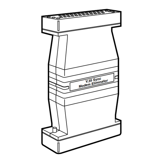
V.35 Sync Modem Eliminator
y n c
V . 3 5 S
t o r
m i n a
m E l i
M o d e
CUSTOMER
Order toll-free in the U.S.: Call 877-877-BBOX (outside U.S. call 724-746-5500)
SUPPORT
FREE technical support 24 hours a day, 7 days a week: Call 724-746-5500 or fax 724-746-0746
INFORMATION
Mailing address: Black Box Corporation, 1000 Park Drive, Lawrence, PA 15055-1018
Web site: www.blackbox.com • E-mail: info@blackbox.com
Advertisement
Table of Contents

Related Manuals for Black Box ME243A-F


Summary of Contents for Black Box ME243A-F
- Page 1 Order toll-free in the U.S.: Call 877-877-BBOX (outside U.S. call 724-746-5500) SUPPORT FREE technical support 24 hours a day, 7 days a week: Call 724-746-5500 or fax 724-746-0746 INFORMATION Mailing address: Black Box Corporation, 1000 Park Drive, Lawrence, PA 15055-1018 Web site: www.blackbox.com • E-mail: info@blackbox.com...
- Page 2 FCC AND DOC/MDC RFI STATEMENTS FEDERAL COMMUNICATIONS COMMISSION INDUSTRY CANADA RADIO FREQUENCY INTERFERENCE STATEMENTS This equipment generates, uses, and can radiate radio-frequency energy, and if not installed and used properly, that is, in strict accordance with the manufacturer’s instructions, may cause interference to radio communication. It has been tested and found to comply with the limits for a Class A computing device in accordance with the specifications in Subpart B of Part 15 of FCC rules, which are designed to provide reasonable protection against such interference when the equipment is...
- Page 3 V.35 SYNC MODEM ELIMINATOR NORMAS OFICIALES MEXICANAS (NOM) ELECTRICAL SAFETY STATEMENT INSTRUCCIONES DE SEGURIDAD 1. Todas las instrucciones de seguridad y operación deberán ser leídas antes de que el aparato eléctrico sea operado. 2. Las instrucciones de seguridad y operación deberán ser guardadas para referencia futura.
- Page 4 NOM STATEMENT 12. Precaución debe ser tomada de tal manera que la tierra fisica y la polarización del equipo no sea eliminada. 13. Los cables de la fuente de poder deben ser guiados de tal manera que no sean pisados ni pellizcados por objetos colocados sobre o contra ellos, poniendo particular atención a los contactos y receptáculos donde salen del aparato.
-
Page 5: Table Of Contents
3.4.1 Closing the Top of the Port-B End ........15 3.4.2 Closing the Middle Section ............ 15 4. Installation and Operation ..............16 5. Troubleshooting ..................18 5.1 Calling Black Box ................18 5.2 Shipping and Packaging ..............18 Appendix: Block Diagram ................19... -
Page 6: Specifications
CHAPTER 1: Specifications 1. Specifications Compliance — CE; FCC Part 15 Class A, DOC Class/MDC classe A Interface — Serial ITU-TSS V.35 Protocol — Synchronous Clock Source — Either internal for both ports or external for Port A and recovered for Port B(user-selectable) Flow Control —... - Page 7 V.35 SYNC MODEM ELIMINATOR 10,000 ft. (3048 m) Maximum Altitude — Temperature Tolerance — 32 to 122˚F (0 to 50˚C) Humidity Tolerance — 5 to 95% noncondensing Power — From the V.35 Interface on both ports: 5 VDC, 6 mA drawn from each port’s RTS and DTR signals (Pins C and H);...
-
Page 8: Introduction
CHAPTER 2: Introduction 2. Introduction With our V.35 Synchronous Modem Eliminator (SME), two synchronous hosts that are not farther apart than 300 ft. (91.4 m) can communicate with each other for a fraction of the cost of a pair of high-speed modems. The V.35 SME supports synchronous data rates of 32, 48, 56, 64, 72, 112, 128, and 144 kbps, and can be configured to emulate dialup or leased-line service. -
Page 9: Configuration
V.35 SYNC MODEM ELIMINATOR 3. Configuration The V.35 Synchonous Modem Eliminator has seven internal user controls— one four-position DIP switch and six jumpers—with which you can configure the unit for a wide range of applications. This chapter tells you how to open, set, and reclose the V.35 SME, and describes all of the unit’s possible configuration settings (including its factory defaults). -
Page 10: Opening The Middle Section
CHAPTER 3: Configuration 3.1.1 O PENING THE IDDLE ECTION Carefully insert a screwdriver, knife, or other tool with a very thin flat blade into the seam along the side of the middle part of the V.35 SME’s housing (the section with the model- and lot-number stickers). Gently twist the tool until the all-plastic top and bottom panels of this housing section begin to pop apart. -
Page 11: Opening The Top Of The Port-B End
V.35 SYNC MODEM ELIMINATOR 3.1.2 O -B E PENING THE OP OF THE This is a tricky procedure, so follow these instructions very carefully. Now that you have the middle section open, find the DIP switch. It is mounted in plain view on top of the V.35 SME’s insides, in one corner of one of the unit’s circuit boards;... -
Page 12: Setting The Dip Switch
CHAPTER 3: Configuration open middle section and out of the unit without damaging it. Just make sure to shake them out over a partitioned-off area of a counter, desktop, etc., so that you don’t lose them if you miss catching them when they come out.) Once you’ve removed both of these screws, firmly grip the housing panel that has to come off and carefully pry it away from the rest of the unit. - Page 13 V.35 SYNC MODEM ELIMINATOR Move positions 1, 2, and 3 of this switch as necessary to select your desired synchronous data rate. (Position 4 is reserved for future use.) Table 3-1 below shows the V.35 SME’s possible data-rate settings. Table 3-1. Data-Rate Settings P.
-
Page 14: Setting The Jumpers
CHAPTER 3: Configuration 3.3 Setting the Jumpers The V.35 SME also has three pairs of jumpers—JP1, JP2, and JP3—mounted on its main circuit board (see Figure 3-4 below; the jumpers are shown in their factory-default settings). Use these jumpers to independently set clocking, carrier, and RTS/CTS delay for Ports A and B. - Page 15 V.35 SYNC MODEM ELIMINATOR JP3: Clock Source The settings of the JP3 jumpers determine whether (a) both devices connected to the V.35 SME use the SME’s internal clock or (b) the device on Port A uses external clock and the device on Port B uses recovered (received) clock.
-
Page 16: Reclosing The Housing
CHAPTER 3: Configuration 3.4 Reclosing the Housing Before you go any further, make absolutely sure the jumper settings are correct, because the last thing you want to do is get the V.35 SME put back together and then have to turn around and disassemble it again. 3.4.1 C -B E LOSING THE... -
Page 17: Installation And Operation
Port A and the device configured for recovered clock is connected to Port B. Sync Host A Sync Host B V.35 SYNC MODEM ELIMINATOR (ME243A-F) Port A Port B 134 ft. 150 ft. (40.8 m) (45.7 m) - Page 18 V.35 SME and of each host device: Which one is supplying the clock? What’s the data-rate setting of each device? And so on. If you’re still having trouble, contact Black Box for technical support (see Section 5.1).
-
Page 19: Troubleshooting
It contains no user- serviceable parts. Contact Black Box Technical Support at (724) 746-5500. Before you do, make a record of the history of the problem. We will be able to... -
Page 20: Appendix: Block Diagram
APPENDIX: Block Diagram Appendix: Block Diagram The figure below is a vastly simplified block diagram showing the general layout of the V.35 Synchronous Modem Eliminator’s circuitry. - Page 21 © Copyright 1997. Black Box Corporation. All rights reserved. 1000 Park Drive • Lawrence, PA 15055-1018 • 724-746-5500 • Fax 724-746-0746...
Need help?
Do you have a question about the ME243A-F and is the answer not in the manual?
Questions and answers