Advertisement
Quick Links
Advertisement

Related Manuals for Moduline GCE 060

Summary of Contents for Moduline GCE 060
- Page 1 SERVICE MANUAL ed. 0317 COMBI OVENS models GCE 060 – 061 – 106 – 101 – 110 T...
- Page 2 INSTALLATION…………………………………………………………………………………………………………………….….3 USE……………………………………………………………………………………………………………………….....8 WARNINGS AND ALARMS……………………………………………………………………………………………………..….10 TECHNICAL DRAWINGS…………………………… …..…………………………………………………………..…..….…..16 ELECTRICAL WIRING DIAGRAMS...…………………………………………………………………………………………..21 PC BOARDS ………………...………...……………………………………………………………………........26 HOW TO ACCESS ON THE SERVICE AREA…………………………………………………………………..……………….29 SUMMARY OF POSSIBLE FAILURES…………………………………………...……………………………………....44 FAILURES AND RELATIVE TECHNICAL INTERVENTIONS………………………………………………………………….55 General fuse replacing Pc board replacing Cavity light fuse replacing Pc board Fuse carrier replacing Pc board Control panel replacing Power pc board replacing...
-
Page 16: Technical Drawings
TECHNICAL DRAWINGS... -
Page 21: Electrical Wiring Diagrams
ELECTRICAL WIRING DIAGRAMS... - Page 26 PC BOARDS...
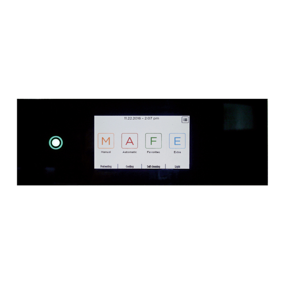
- Page 29 HOW TO ACCESSON SERVICE AREA 1) Turn on the oven with the switch “On-Off” and then select the icon on the corner. 2) Select “Service area”. 3) Insert the password “111” and confirm it with OK. 4) In the Service area, you will find 4 menus: •...
- Page 30 SISTEM 1) Select “System”. Under “System” there are 5 icons 2) You can change: • Language • Date • Time • Temperature scale • Time zone...
- Page 31 Select “TIME ZONE” to put the correct time of the area where are you are. Summer/ wintertime will change automatically.
- Page 32 SERVICE 1) Select “Service”. Under “Service” you will find 6 icons 2) You can check: • Info • Parameters • Test • Rectricted area • Telemetry data • Note 3) Select “Info”. You will see information about the software loaded on the appliance. 4) Select “Parameters”.
- Page 33 5) To check other parameters use the 2 arrows. If you need to change the parameter value, select the new value on the keyboard and confirm by pressing 6) If you want to put all the parameters as default values, select “DEFAULT” 7) You will see the message “SET DEFAULTS”.
- Page 34 8) Select “Test” area. On the screen you can check the relays, the temperature probes, ecc. Power pc board Relays: • RL1 = cavity humidification valve • RL2 = not used • RL3 = cavity light • RL4 = contactor of cavity heating element (2/3 of power) •...
- Page 35 Expansion pc board: Relays: • RL1B= pump • RL14B = motor valve • RL…B= not used Temperature probes: • T…B = not used Digital inputs: • D1B = flowmeter • D…B = not used High voltage inputs: • HV…B = not used Water levels: •...
- Page 36 9) Select “Telemetry data”. You can download them on a USB stick, remove the telemetry or the figures relating to the appliance activity (closure and opening contacts, temperature recorder, relays, etc ...). This allows the user to check needed information and identify any problem. 10) Select “Note”...
- Page 37 CONNECTIONS Select “Connections”.
-
Page 38: Upload / Download
UPLOAD / DOWNLOAD 1) Select “UPLOAD/DOWNLOAD”. - Page 39 Haccp...
-
Page 40: Software Upgrade
SOFTWARE UPGRADE 1) Take the software file “forno_________upgr” and put it into an empty USB key. 2) Select “UPLOAD/DOWNLOAD”. 3) Select “SW UPGRADE” and then select “UPGRADE”. 4) On the display you will see the message (or similar) shown the picture below. Select YES. - Page 41 5) Now the software update will start. If a bar appears, wait until it is completely black 6) At the end of the update, the oven automatically turns off e then turns on. Then will appear the message “Software restore from sd card ?”. Select “NO”. 7) Then will appear the message “SET DEFAULTS”.
- Page 42 SERVICE FILE UPDATE 1) Extract the SERVICE file from the zip folder“service_upg_______”into an empty USB key. 2) Turn off the oven’s power with the switch “On-Off”. 3) Insert the USB key into the oven’s USB port. 4) Turn on the oven’s power with the switch “On-Off”. Appear on the screen “Service Upgrade”. Push Ok to confirm.
- Page 43 SAVING DIAGRAM OF THE PC BOARD TABLET POWER PC BOARD Inside the tablet are saved: 1) App software Inside the tablet are saved: 2) Service software 5) Parameters 3) Factory recipes 4) Favorites recipes MIICRO SD Backup copy inside the micro sd: 1) App software 3) Factory recipes 4) Favorites recipes...
- Page 44 SUMMARY OF POSSIBLE DEFAULTS Problem Possible cause Solution No electrical power Restore electrical power Main switch faulty Replace main switch PC board fuse damaged Replace PC board fuse The control panel does Power cable not properly connected Check power cable connection not switch on Control panel pc board faulty Replace control panel pc board...
- Page 45 Check electric connections inside the Electric connections faulty appliance Software parameters not correct Check parameters The cavity does not heat enough A heating element is nurnt, if there are more than one heating element in Replace heating element the appliance Cavity probe faulty Replace cavity probe Software parameters not correct...
- Page 46 appears on the display Core probe socket not properly and the buzzer starts Connect core probe socket properly connected or disconnected Core probe socket faulty Replace core probe socket Software problem Reload the software Power pc board faulty Replace power pc board Drain probe not properly connected Connect the drain probe properly or disconnected...
- Page 47 buzzer starts Power pc board faulty Replace power pc board General fuse blown Replace general fuse Check electric connections inside the Electric connections faulty appliance “Alarm fan thermal Motor fan faulty Replace motor fan protection” appears on the display and the buzzer starts Motor fan capacitor faulty Replace the motor fan capacitor...
- Page 48 appears on the display Tank not in correct position (only for Check the tank position and the buzzer starts model with water tank) Water pressure switch faulty Replace water pressure switch Check electric connections inside the Electric connections faulty appliance Power pc board faulty Replace power pc board Water tank switch faulty...
- Page 49 starts Expansion pc board faulty Replace expansion pc board Software problem Reload the software Light bulb damaged Replace light bulbs Incorrect PC board parameters Reset PC board parameters The oven light doesn’t turn on Check electric connections inside the Electric connections faulty appliance Power pc board faulty Replace power pc board...
- Page 50 cooling fan doesn’t work Check electric connections inside the Electric connections faulty appliance Software problem Reload the software Core probe not properly connected or Connect core probe properly disconnected Core probe faulty Replace core probe Power pc board faulty Replace power pc board The core probe doesn’t work Software problem...
- Page 51 work Power pc board faulty Replace power pc board Motor fan capacitor faulty Replace the motor fan capacitor Software problem Reload the software Replace the water humidification The water humidification valve faulty valve Injection water pipe blocked Clean the injection water pipe Check electric connections inside the Electric connections faulty The humidification water...
- Page 52 No water inlet to the water Check the inlet to the water connection of the oven connection of the oven Hand shower Hand shower faulty Replace the hand shower Pen drive problem Use a new pen drive Check the electric connections inside Electric connections faulty the appliance The usb socket is not...
- Page 53 doesn’t work Software problem Reload the software The distance from the upper part of Reduce the distance from the door to the door to the control panel is too the control panel high Check the electric connections inside Electric connections faulty the appliance The door magnetic Magnetic switch faulty...
- Page 54 doesn’t work well Pump faulty Replace the pump Drain motor valve faulty Replace the drain motor valve Software problem Reload the software...
- Page 55 FAILURES AND RELATIVE TECHNICAL INTERVENTIONS Before proceeding with the intervention, make sure that the electric cable of the appliance is unplugged. - REPLACEMENT OF GENERAL FUSE To replace the general fuse, proceed as follows: 1) Remove the control panel by unscrewing the 4 screws indicated. 2) Disconnect the electrical cables of the control panel.
- Page 56 3) Remove the electrical connector of the core probe wires from the power pc board. 4) Remove the 2 seals of the pipes on the appliance upper surface. 5) Remove the cover of the appliance by unscrewing the screws (3 screws on each side). It is not necessary to remove the screws completely but just unscrew them slightly.
- Page 57 6) Identify the general fuse and open the fuse carrier by pulling it out. 7) Close to the working fuse, you will find an extra fuse. Remove the fuse and damaged insert the extra fuse. Value of the fuse = 5A. 8) Relocate again the fuse carrier in its place.
- Page 58 - REPLACEMENT OF PC BOARD FUSE To replace the pc board fuse, proceed as follows: 1) Remove the control panel of the appliance by unscrewing 4 screws. 2) Disconnect the electrical cables of the control panel.
- Page 59 3) Remove the electrical connector of the core probe wires from the power pc board. 4) Remove the 2 seals of the pipes on the appliance upper cover. 5) Remove the cover of the appliance by unscrewing the screws (3 screws on each side). It is not necessary to remove the screws completely but just unscrew them slightly.
- Page 60 6) Identify the pc board fuse and open the fuse carrier by pulling it out. 7) Close to the working fuse, you will find an extra fuse. Remove the fuse and damaged insert the extra fuse. Value of the fuse = 2A. 8) Relocate again the fuse carrier in its place.
- Page 61 - REPLACEMENT OF CAVITY LIGHT FUSE To replace the cavity light fuse, proceed as follows: 1) Remove the control panel of the appliance by unscrewing 4 screws. 2) Disconnect the electrical cables of the control panel.
- Page 62 3) Remove the electrical connector of the core probe wires from the power pc board. 4) Remove the 2 seals of the pipes on the appliance upper cover. 5) Remove the cover of the appliance by unscrewing the screws (3 screws on each side). It is not necessary to remove the screws completely but just unscrew them slightly.
- Page 63 6) Identify the cavity light fuse and open the fuse carrier by pulling it outwards. 7) Close to the fuse, you will find an extra fuse. Remove the fuse and damaged insert the extra fuse. Value of the fuse = 250mA. 8) Relocate again the fuse carrier in its place.
- Page 64 REPLACEMENT OF FUSE CARRIER To replace the fuse carrier, proceed as follows: 1) Remove the control panel of the appliance by unscrewing 4 screws. 2) Disconnect the electrical cables of the control panel.
- Page 65 3) Remove the electrical connector of the core probe wires from the power pc board. 4) Remove the 2 seals of the pipes on the appliance upper cover. 5) Remove the cover of the appliance by unscrewing the screws (3 screws on each side). It is not necessary to remove the screws completely but just unscrew them slightly.
- Page 66 6) Identify the fuse carriers (there are 3 fuse carriers inside the appliance) and disconnect the electric wires from their terminals. 7) Pull ahead the fuse carrier until it is completely away from the metal part. 8) Close the appliance repeating the operations described in the opposite way.
- Page 67 - REPLACEMENT OF CONTROL PANEL To replace the control panel, proceed as follows: 1) Remove the control panel of the appliance by unscrewing 4 screws. 2) Disconnect the electrical cables of the control panel.
- Page 68 3) Remove the electrical connector of the core probe wires from the power pc board. 4) Remove the micro sd card from the faulty control panel and insert it into the new control panel.
- Page 69 5) Assemble the new control panel repeating the operations t described in the above opposite way. 6) Turn on the appliance. On the display you can see: - SOFTWARE RESTORE FROM SD CARD? Select YES to copy the backup software / data base from the micro usb memory to the new control panel.
- Page 70 - REPLACEMENT OF POWER PC BOARD To replace the power pc board, proceed as follows: 1) Remove the control panel of the appliance by unscrewing 4 screws. 2) Disconnect the electrical cables of the control panel.
- Page 71 3) Remove the electrical connector of the core probe wires from the power pc board. 4) Remove the 2 seals of the pipes on the appliance upper cover. 5) Remove the cover of the appliance by unscrewing the screws (3 screws on each side). It is not necessary to remove the screws completely but just unscrew them slightly.
- Page 72 6) Disconnect the electrical cables of the power pc board. Remove the screws that fix the power pc board. 7) Replace the faulty power pc board with the new power pc board. 8) Assemble the new pc board repeating the operations described in the opposite way.
- Page 73 At the end of the update, the oven automatically turns off e then turns on. 12) On the display you can see: - PARAMETERS RESTORE FROM SD CARD ? Select YES to copy the backup parameters from the micro usb memory to the new power pc board. and / or - SOFTWARE RESTORE FROM SD CARD? Select YES to copy the backup software / data base from the micro usb memory to the new control panel.
- Page 74 - REPLACEMENT OF EXPANSION PC BOARD To replace the expansion pc board, proceed as follows: 1) Remove the control panel of the appliance by unscrewing 4 screws. 2) Disconnect the electrical cables of the control panel.
- Page 75 3) Remove the electrical connector of the core probe wires from the power pc board. 4) Remove the 2 seals of the pipes on the appliance upper cover 5) Remove the cover of the appliance by unscrewing the screws (3 screws on each side). It is not necessary to remove the screws completely but just unscrew them slightly.
- Page 76 6) Disconnect the electrical cables of the power pc board. 7) Remove the screws that fix the expansion pc board. 8) Replace the faulty expansion pc board with the new power pc board. 9) Assemble the appliance repeating the operations t described in the opposite way.
- Page 77 - REPLACEMENT OF PC BOARD BUZZER To replace the PC board buzzer, proceed as follows: 1) Remove the control panel of the appliance by unscrewing 4 screws; 2) Disconnect the electrical cables of the control panel.
- Page 78 3) Remove the electrical connector of the core probe wires from the power pc board. 4) Remove the 2 seals of the pipes on the appliance upper cover 5) Remove the cover of the appliance by unscrewing the screws (3 screws on each side). It is not necessary to remove the screws completely but just unscrew them slightly.
- Page 79 6) Disconnect the buzzer cable and use a tool to detach the buzzer from the metal panel to which it is fixed through a double-sided adhesive tape. 7) Reposition the new buzzer in the same position, securing it with double-sided adhesive tape.
- Page 80 - REPLACEMENT OF CORE PROBE SOCKET To replace the core probe socket, proceed as follows: 1) Remove the control panel of the appliance by unscrewing 4 screws; 2) Disconnect the electrical cables of the control panel.
- Page 81 3) Remove the electrical connector of the core probe wires from the power pc board. 4) Remove the 2 seals of the pipes on the appliance upper cover 5) Remove the cover of the appliance by unscrewing the screws (3 screws on each side). It is not necessary to remove the screws completely but just unscrew them slightly.
- Page 82 6) Disconnect the 4 wires of the core probe socket from the power pc board making sure you take note of their connections. 7) Unscrew the 2 screws that fix the socket core probe. Pull out the core probe socket from the outside of the appliance and replace it with the new probe socket.
- Page 83 - REPLACEMENT OF USB SOCKET To replace the usb socket, proceed as follows: 1) Remove the control panel of the appliance by unscrewing 4 screws; 2) Disconnect the electrical cables of the control panel.
- Page 84 3) Remove the electrical connector of the core probe wires from the power pc board. 4) Remove the 2 seals of the pipes on the appliance upper cover 5) Remove the cover of the appliance by unscrewing the screws (3 screws for each side). It is not necessary to remove the screws completely but only just unscrew them slightly.
- Page 85 6) Disconnect the usb cable and unscrew the plastic nut of the usb socket. 7) Pull out the usb socket from the outside of the appliance machine and replace it with the new usb socket. 8) Assemble the appliance repeating the operations t described in the opposite way.
- Page 86 - REPLACEMENT OF COOLING FAN PC BOARD COMPARTMENT To replace the fan inside the pc board compartment, proceed as follows: 1) Remove the control panel of the appliance by unscrewing 4 screws; 2) Disconnect the electrical cables of the control panel.
- Page 87 3) Remove the electrical connector of the core probe wires from the power pc board. 4) Remove the 2 seals of the pipes on the appliance upper cover 5) Remove the cover of the appliance by unscrewing the screws (3 screws on each side). It is not necessary to remove completely the screws but just unscrew them slightly.
- Page 88 6) Disconnect the electric wires of the fan and unscrew the 2 screws which fix the fan cooling fan. 7) Reposition the new fan in the same position and fix it with 2 screws. Reconnect the fan electrically; 8) Assemble the appliance repeating the operations t described in the opposite way.
- Page 89 - REPLACEMENT OF COOLING FAN BACK COMPARTMENT To replace the fan inside the back compartment, proceed as follows: 1) Remove the back panels of the appliance by unscrewing the screws (2 screws on each side). 2) Remove the screws that fix the metal bracket of the cooling fan.
- Page 90 3) Disconnect the electric wires of the fan and unscrew the screws which fix the fan cooling fan. 4) Reposition the new fan in the same position and fix it with the screws. Reconnect the fan electrically. 5) Assemble the appliance repeating the operations t described in the opposite way.
- Page 91 - RESTORE OF CAVITY SAFETY THERMOSTAT To restore the cavity safety thermostat, proceed as follows: 1) Unscrew the screw situated on the upper part of the appliance. 2) Using a tool, push inside the hole to restore the safety thermostat. 3) Then screw again the screw.
- Page 92 REPLACEMENT OF CAVITY SAFETY THERMOSTAT To replace the cavity safety thermostat, proceed as follows: 1) Remove the control panel of the appliance by unscrewing 4 screws. 2) Disconnect the electrical cables of the control panel.
- Page 93 3) Remove the electrical connector of the core probe wires from the power pc board. 4) Remove the 2 seals of the pipes on the appliance upper cover. 5) Remove the cover of the appliance by unscrewing the screws (3 screws on each side). It is not necessary to remove the screws completely but just unscrew them slightly.
- Page 94 6) Unscrew the 2 screws which fix the thermostat to the metal support bracket. Disconnect the electric wires of the safety thermostat, making sure you take note of their connection position. 7) Remove the back panels of the appliance by unscrewing the screws (2 screws on each side).
- Page 95 8) Remove the guides from the cavity. Then remove the deflector from the cavity using a tool. It is necessary to turn the 4 locks using a tool.
- Page 96 9) By following the capillary of the thermostat, you will be able to identify the cavity safety thermostat. 10) Unscrew the metal nut that fix the safety thermostat. 11) Pull out the safety thermostat from the cavity and replace it with the new safety thermostat;...
- Page 97 REPLACEMENT OF CAVITY TEMPERATURE PROBE To replace the cavity temperature probe, proceed as follows: 1) Remove the control panel of the appliance by unscrewing 4 screws; 2) Disconnect the electrical cables of the control panel.
- Page 98 3) Remove the electrical connector of the core probe wires from the power pc board. 4) Remove the 2 seals of the pipes on the appliance upper cover 5) Remove the cover of the appliance by unscrewing the screws (3 screws on each side). It is not necessary to remove the screws completely but just unscrew them slightly.
- Page 99 6) Disconnect the electric 2 wires of cavity temperature probe from the power pc board, making sure you take note of their connection position; 7) Remove the back panels of the appliance by unscrewing the screws (2 screws on each side).
- Page 100 8) By following the wire of the cavity temperature probe, you will be able to identify the cavity temperature probe. 9) Unscrew the brass nut that fix the cavity temperature probe to the cavity. 10) Pull out the cavity temperature probe and fix the new cavity temperature probe. 11) Assemble the appliance repeating the operations t described in the opposite way.
- Page 101 - SAFETY CONTACTOR REPLACING To replace the safety contactor, proceed as follows: 1) Remove the control panel of the appliance by unscrewing 4 screws. 2) Disconnect the electrical cables of the control panel.
- Page 102 3) Remove the electrical connector of the core probe wires from the power pc board. 4) Remove the 2 seals of the pipes on the appliance upper cover 5) Remove the cover of the appliance by unscrewing the screws (3 screws on each side). It is not necessary to remove the screws completely but only just unscrew them slightly.
- Page 103 6) Identify the safety contactor and disconnect the electric wires before replacing it, making sure you take of their connection position; 7) Pull the safety contactor until that it is completely away from the metal part and then position the new contactor in the same position. 8) Assemble the appliance repeating the operations above described in the opposite way.
- Page 104 - REPLACEMENT OF HEATING ELEMENT CONTACTORS To replace the heating element contactors, proceed as follows: 1) Remove the control panel of the appliance by unscrewing 4 screws. 2) Disconnect the electrical cables of the control panel.
- Page 105 3) Remove the electrical connector of the core probe wires from the power pc board. 4) Remove the 2 seals of the pipes on the appliance upper cover. 5) Remove the cover of the appliance by unscrewing the screws (3 screws on each side). It is not necessary to remove the screws completely but just unscrew them slightly.
- Page 106 6) Identify the safety contactor faulty and disconnect the electric wires before replacing it, making sure you take note of their connection position. 7) Pull the safety contactor until it completely away from the metal part and then place the new contactor in the same position.
- Page 107 - REPLACEMENT OF CAVITY HEATING ELEMENT To replace the cavity heating element, proceed as follows: 1) Remove the guides from the cavity. Remove the deflector from the cavity using a tool. It is necessary to turn the 4 locks using a tool.
- Page 108 2) Remove the back panels of the appliance by unscrewing the screws (2 screws on each side). 3) Remove the electrical connections of the heating element making sure you take note of their connection position.
- Page 109 4) Unscrew the screws that fix the heating element brackets to the cavity. 5) Remove the heating element out and clean the area where the heating element bracket is placed. Remove all silicone residues. 6) Take a new heating element and put alimentary silicone on its flange (on the part that comes into contact with the cavity).
- Page 110 - CLIMACHEF VENT PROBE REPLACING To replace the “Climachef” vent probe, proceed as follows: 1) Remove the control panel of the appliance by unscrewing 4 screws. 2) Disconnect the electrical cables of the control panel.
- Page 111 3) Remove the electrical connector of the core probe wires from the power pc board. 4) Remove the 2 seals of the pipes on the appliance upper cover. 5) Remove the cover of the appliance by unscrewing the screws (3 screws on each side). It is not necessary to remove the screws completely but just unscrew them slightly.
- Page 112 6) Disconnect the 2 electric wires of the Climachef vent probe from the power pc board, making sure you take note of their connection position. 7) Remove the back panels of the appliance by unscrewing the screws (2 screws on each side).
- Page 113 8) By following the wire of the Climachef vent probe, you will be able to identify the probe. 9) Cut the plastic clamp and remove the silicon around the probe and pull out the Climachef vent probe.
- Page 114 10) Remove all silicone residues from the pipe and fix the new probe. 11) Fill up the hole of the probe with alimentary silicone to stop humidity. To ensure that the silicone dries correctly and forms a seal, wait 24 hours before turning the machine on and heating the cooking cavity.
- Page 115 REPLACEMENT OF MOTOR FAN To replace the motor fan, proceed as follows: 1) Remove the guides from the cavity. Then remove the deflector from the cavity using a tool. It is necessary to turn the 4 locks using a tool.
- Page 116 2) Remove the back panels of the appliance by unscrewing the screws (2 screws on each side). 3) Take off the fan out of the motor unscrewing the screw that secures it to the motor shaft. Pay attention at the correct assembly of the screw and washers. To remove the fan it is necessary to use an extractor tool.
- Page 117 5) Remove the 4 screws that secure the motor to the cavity so that the motor can be pulled out. 6) Take the new motor and fasten it to the cavity using the 4 screws previously mentioned. 7) Assemble the new fan, being very careful to put the washer and the screw in their original position, and tighten them firmly.
-
Page 118: Fan Replacement
FAN REPLACEMENT To replace the fan, proceed as follows: 1) Remove the guides from the cavity. Then remove the deflector from the cavity using a tool. It is necessary to turn the 4 locks using a tool. - Page 119 2) Take off the fan out of the motor unscrewing the screw that secures it to the motor shaft. Pay attention at the correct assembly of the screw and washers. To remove the fan it is necessary to use an extractor tool. 3) Assemble the new fan, being very careful to put the washer and the screw in their original positions, and tighten them firmly.
- Page 120 REPLACEMENT OF MOTOR FAN CAPACITOR To replace the motor fan capacitor, proceed as follows: 1) Remove the control panel of the appliance by unscrewing 4 screws. 2) Disconnect the electrical cables of the control panel.
- Page 121 3) Remove the electrical connector of the core probe wires from the power pc board. 4) Remove the 2 seals of the pipes on the appliance upper cover. 5) Remove the cover of the appliance by unscrewing the screws (3 screws on each side). It is not necessary to remove the screws completely but just unscrew them slightly.
- Page 122 6) Disconnect the electrical cables of the faulty capacitor and unscrew the nut that clamps it mechanically. 7) Put the new capacitor, reconnect the electrical cables and secure it with the nut. 8) Assemble the appliance repeating the operations above described in the opposite way.
- Page 123 REPLACEMENT OF “CLIMACHEF” MOTOR To replace the ”Climachef” motor, proceed as follow: 1) Remove the control panel of the appliance by unscrewing 4 screws. 2) Disconnect the electrical cables of the control panel.
- Page 124 3) Remove the electrical connector of the core probe wires from the power pc board. 4) Remove the 2 seals of the pipes on the appliance upper cover. 5) Remove the cover of the appliance by unscrewing the screws (3 screws for each side). It is not necessary to remove completely the screws completely but just unscrew them slightly.
- Page 125 6) Remove the back panels of the appliance by unscrewing the screws (2 screws on each side). 7) Remove the screws that fix the motor tree to the opening/closing system inside the pipe. Before removing the screws, take note of the correct position of the motor cam and of the correct position of the cam inside the pipe.
- Page 126 10) Take the new motor and secure it to the anchoring bracket using the screws that were previously removed. 11) Fix the motor tree to the opening/closing system inside the pipe and re-connect the electrical connectors. Be careful to fasten the cam inside the pipe in the right position: - when the appliance is in stand-by (no programme is running), the pipe cap must be open;...
- Page 127 - REPLACEMENT OF CAVITY HUMIDIFICATION VALVE To replace the humidification valve, proceed as follow: 1) Remove the back panels of the appliance by unscrewing the screws (2 screws on each side). 2) Detach from the valve the plastic pipe and the electric connection.
- Page 128 3) Unscrews the 2 screws that fix the valve. 4) Remove the water pressure switch from the faulty humidity valve. Then reassemble the pressure switch on the new humidity valve. 5) Assemble the new humidity valve by connecting the plastic pipe and the 2 electric connections.
- Page 129 - REPLACEMENT OF WATER PRESSURE SWITCH To replace the water pressure switch, proceed as follow: 1) Remove the back panels of the appliance by unscrewing the screws (2 screws on each side). 2) Detach from the pressure switch the 2 electric connections, taking care to mark down their correct positions.
- Page 130 CAVITY LIGHT BULBS To replace the cavity light bulbs, proceed as follows: 1) After having removed the guides, unscrew the 4 screws that fix the metal frame of the lamp. Remove the metal frame, the gasket and the glass. Then replace the faulty light bulb. 2) Replace it by following the procedure described in point 1 in the opposite way.
- Page 131 REPLACEMENT OF DOOR MAGNETIC SENSOR To replace the door magnetic sensor, proceed as follow 1) Remove the control panel of the appliance by unscrewing 4 screws; 2) Disconnect the electrical cables of the control panel.
- Page 132 3) Remove the electrical connector of the core probe wires from the power pc board. 4) Disconnect the magnetic sensor cable and use a tool to pull out the sensor from the metal panel to which it is fixed by a double-sided adhesive tape. 5) Reposition the new magnetic sensor in the same position, securing it with the double-sided adhesive tape.
- Page 133 - CALIBRATING DOOR CLOSING AND CHECKING DOOR GASKET If the door does not close completely and the gasket does not guarantee hermetic closing, proceed as follows to fix it: 1) Remove the rubber cover and unscrew the metal nut that fix the retaining hook. Then screw the retaining hook for 360°...
- Page 134 3) In this way the gasket will guarantee correct sealing by pressing more firmly against the door. If this operation does not guarantee correct sealing, the door gasket must be replaced.
-
Page 135: Replacement Of Door Gasket
- REPLACEMENT OF DOOR GASKET To replace the door gasket, proceed as follows: 1) Open the door and remove the gasket from its seat (the gasket is fixed with silicone only in the corners). 2) Use a degreasing product to clean accurately the seat where the damaged gasket was placed. - Page 136 - REPLACEMENT OF DRAIN CONDENSATION VALVE To replace the drain condensation valve, proceed as follow: 1) Remove the back panels of the appliance by unscrewing the screws (2 screws on each side). 2) Pull out the valve from the plastic pipe and the electric connection. 3) Pull out the plastic pipe and the electric connections from the valve.
- Page 137 4) Unscrews the 2 screws that fix the valve. 5) Assemble the new condensation valve by connecting the plastic pipe and the electric connections. 6) Assemble the appliance repeating the operations above described in the opposite way.
- Page 138 - REPLACEMENT OF MAIN SWITCH To replace the main switch, proceed as follows: 1) Open the door and unscrew the screws (3 screws) situated in the bottom part of the cavity. 2) Put the oven screws (3 screws) located on the bottom part of on its side and unscrew the the oven.
- Page 139 3) Then screws (6 screws) to remove the bottom cover of the oven. unscrew the Unscrew the metal clamp of the drain pipe and remove the silicone pipe connection. Now you can remove the front / bottom part of the oven (where the main switch is located).
- Page 140 5) Disconnect the electric wires of the main switch, making sure you take note of their connection position. Unscrew the metal nut of the main switch and pull it out from the front panel. Replace it with the new main switch. 6) Assemble the appliance repeating the operations above described in the opposite way.
- Page 141 - REPLACEMENT OF DRAIN TEMPERATURE PROBE To replace the drain temperature probe, proceed as follows: 1) Remove the control panel of the appliance by unscrewing 4 screws. 2) Disconnect the electrical cables of the control panel.
- Page 142 3) Remove the electrical connector of the core probe wires from the power pc board. 4) Remove the 2 seals of the pipes on the appliance upper cover. 5) Remove the cover of the appliance by unscrewing the screws (3 screws on each side). It is not necessary to remove the screws completely but just unscrew them slightly.
- Page 143 6) Disconnect the 2 electric wires of the temperature probe from the power pc board, making sure you take note of their connection position. 7) Disconnect the 2 electric wires of drain temperature probe from the power pc board, making sure you take note of their connection position. 8) Remove the back panels of the appliance by unscrewing the screws (2 screws for each side).
- Page 144 9) Put the oven screws (6 screws) to remove the bottom cover of on its side and unscrew the the oven.
- Page 145 10) By following the wire of the drain temperature probe, you will be able to identify the drain temperature probe. 11) Unscrew the brass nut that fix the drain temperature probe to the drain pipe. 12) Pull out the drain temperature probe and fix the new drain temperature probe. 13) Assemble the appliance repeating the operations above described in the opposite way.
- Page 146 - REPLACEMENT OF FLOWMETER (WITH SELF CLEANING OPTION) To replace the flowmeter, proceed as follow: 1) Remove the control panel of the appliance by unscrewing 4 screws. 2) Disconnect the electrical cables of the control panel.
- Page 147 3) Remove the electrical connector of the core probe wires from the power pc board. 4) Remove the 2 seals of the pipes on the appliance upper cover. 5) Remove the cover of the appliance by unscrewing the screws (3 screws on each side). It is not necessary to remove the screws completely but just unscrew them slightly.
- Page 148 6) Disconnect the 2 electric wires of the flowmeter from the power pc board, making sure you take note of their connection position. 7) Remove the back panels of the appliance by unscrewing the screws (2 screws on each side).
- Page 149 8) By following the wire of the cavity temperature probe, you will be able to identify the cavity temperature probe. 9) Unscrew the 2 metal clamps that connect the flowmeter to water pipes. 10) Remove the faulty flowmeter and and fix the new one. 11) Assemble the appliance repeating the operations above described in the opposite way.
- Page 150 - REPLACEMENT OF MOTOR DRAIN VALVE (WITH SELF CLEANING OPTION) To replace the motor drain valve, proceed as follow: 1) Put the oven screws (6 screws) to remove the bottom cover of on its side and unscrew the the oven. 2) Disconnect the electric wires of the motor drain valve.
- Page 151 3) Assemble the new drain motor valve. 4) Assemble the appliance repeating the operations above described in the opposite way...
- Page 152 PUMP REPLACEMENT (WITH SELF CLEANING OPTION) To replace the pump, proceed as follows: 1) Put the oven screws (6 screws) to remove the bottom cover of on its side and unscrew the the oven. 2) Disconnect the electric wires of the pump. Unscrew the 2 metal clamps that connect the pump to the water pipes.
- Page 153 3) Assemble the appliance repeating the operations above described in the opposite way.
- Page 154 - HAND SHOWER REPLACEMENT (WITH HAND SHOWER OPTION) To replace the hand shower, proceed as follows: 1) Open the door and unscrew the screws (3 screws) located on the bottom part of the cavity. 2) Put the oven screws (3 screws) located on the bottom part of on its side and unscrew the the oven.
- Page 155 3) Then screws (6 screws) to remove the bottom cover of the oven. unscrew the Unscrew the metal clamp of the drainpipe and remove the silicone pipe connection. Now you can remove the front / bottom part of the oven (where the main switch is located).
- Page 156 5) Remove the 2 screws that fix the metal bracket of the hand shower. 6) Then remove the 4 screws that fix the hand shower located under the metal bracket. 7) Disconnect the water plastic pipe from the hand shower.
- Page 157 8) Pull out the hand shower from the front panel. 9) Replace the damaged hand shower with the new one 10) Assemble the appliance repeating the operations above described in the opposite way.
Need help?
Do you have a question about the GCE 060 and is the answer not in the manual?
Questions and answers