Table of Contents
Advertisement
Available languages
Available languages
Quick Links
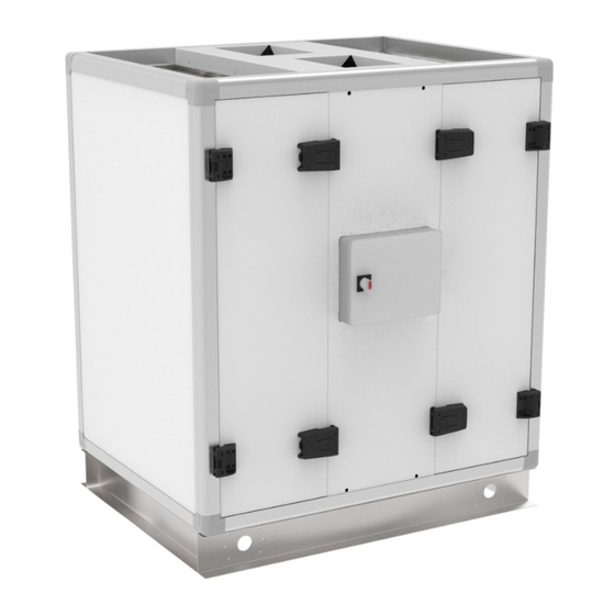
Unité de ventilation double flux avec récupération d'énergie à haut rendement
Ventilatiekasten met dubbele luchtstroom en hogerendement warmteterugwinning
High efficiency double flow ventilation unit with high efficiency heat recovery
Hocheffiziente Lüftungseinheit mit hocheffizienter Wärmerückgewinnung
Manuel d'installation et de maintenance
Installatie- en onderhoudshandleiding
Installation and maintenance manual
Installations- und Wartungsanleitung
1
Advertisement
Chapters
Table of Contents

Related Manuals for P.LEMMENS HRup 800

Summary of Contents for P.LEMMENS HRup 800
- Page 1 Unité de ventilation double flux avec récupération d’énergie à haut rendement Ventilatiekasten met dubbele luchtstroom en hogerendement warmteterugwinning High efficiency double flow ventilation unit with high efficiency heat recovery Hocheffiziente Lüftungseinheit mit hocheffizienter Wärmerückgewinnung Manuel d’installation et de maintenance Installatie- en onderhoudshandleiding Installation and maintenance manual Installations- und Wartungsanleitung...
- Page 2 Version française: voir page 3 Nederlandse versie: zie pagina 14 English version : see page 25 Deutsche Version: siehe Seite 36...
-
Page 3: Table Of Contents
TABLE DES MATIERES 1. GENERALITES ..........................4 1.1 Construction ..........................4 1.2 Ventilateurs à technologie TAC ....................4 1.3 Echangeur à contreflux AIR/AIR ....................4 1.4 Filtres ............................5 1.5 Fiche de configuration de votre installation ................5 1.6 Garantie ..........................5 1.7 Conformité... -
Page 4: Generalites
1. GENERALITES 1.1 Construction La structure du caisson est autoportante, les panneaux sont à double parois de 50 mm (30 mm pour HRup 450) et l’ensemble est libre de ponts thermiques. L'extérieur est en acier pré-peint, l'intérieur en acier galvanisé. L’isolation thermique et phonique est réalisée en laine de roche ignifugée (Euroclass A1, EN 13501), conforme aux normes européennes sur l’environnement, insérées entre les tôles. -
Page 5: Filtres
1 x G4 510014 HRup 450 415x200x50 1 x F7 1 x F7 510071 1 x M5 510089 HRup 800 470x287x50 1 x F7 1 x F7 510072 1 x M5 510090 HRup 1200 830x287x50 1 x F7 1 x F7... -
Page 6: Installation De L'unite
2. INSTALLATION DE L’UNITE 2.1 Mise en place de l’unité La série HRup est montée sur embase, et est fabriquée en une seule pièce (monobloc). La conception de l’unité ne permet pas de démonter l’embase car celle-ci assure la rigidité de l’ensemble. L’embase est pourvue de trous permettant d’y glisser des barres pour toute opération de levage et/ou de mise en place. -
Page 7: Instructions De Raccordement Des Alimentations
3. INSTRUCTIONS DE RACCORDEMENT DES ALIMENTATIONS 3.1 Informations générales 3.1.1 Schéma général des unités HRup 1. Interrupteur général pour l’alimentation en puissance des ventilateur et de la régulation 2. Interrupteur général pour l’alimentation en puissance des batteries électriques de pré/postchauffe KWin/KWout (options) 3. -
Page 8: Schéma De Principe Du Positionnement Des Sondes De T° Dans L'unité
Courant maximum Type de protection (2) Calibre de la protection HRup 450 1 x 230V 3,1 A D – 10.000A – AC3 HRup 800 1 x 230V 5,5 A D – 10.000A – AC3 HRup 1200 1 x 230V 7,0 A D –... -
Page 9: Raccordement De La Batterie Eau De Post-Chauffe Nv (Option)
Spécifications du raccordement: Type d’unité Raccords Raccords Puissance (*) Débit d’eau (*) Perte de charge (*) échangeur vanne 3 voies HRup 800 1/2’’ G 1B 4,5 kW 199 l/h 1,4 kPa HRup 1200 1/2’’ G 1B 7,7 kW 339 l/h... -
Page 10: Regulation
4. REGULATION Les fonctionnalités de base de la régulation sont : Pilotage des ventilateurs Gestion automatique de plages horaires Gestion automatique du bypass (freecooling) Gestion automatique de la protection antigel du récupérateur Gestion automatique des clapets montés à l’aspiration Régulation de la batterie de préchauffe électrique (si montée) Régulation de la batterie de postchauffe eau ou électrique (si montée) Le circuit de base de la régulation est monté... -
Page 11: Entretien
1 x G4 510014 HRup 450 415x200x50 1 x F7 1 x F7 510071 1 x M5 510089 HRup 800 470x287x50 1 x F7 1 x F7 510072 1 x M5 510090 HRup 1200 830x287x50 1 x F7 1 x F7... - Page 12 1 x G4 510014 HRup 450 415x200x50 1 x F7 1 x F7 510071 1 x M5 510089 HRup 800 470x287x50 1 x F7 1 x F7 510072 1 x M5 510090 HRup 1200 830x287x50 1 x F7 1 x F7...
-
Page 13: Annexe: Paramètres De L'installation
ANNEXE: Paramètres de l’installation Afin de faciliter toute intervention future, indiquez dans ce tableau tous les paramètres propres à votre installation. Veuillez vous munir de ce document complété avant de nous contacter pour tout problème éventuel. Sans cela nous ne serons pas en mesure de vous aider. Paramètres de configuration: Type de HRup Mode de fonctionnement... - Page 14 INHOUDSTABEL 1. ALGEMEEN ..........................15 1.1 Constructie ..........................15 1.2 TAC ventilatoren ........................15 1.3 Lucht/Lucht tegenstroom warmtewisselaar ................15 1.4 Filters ............................ 16 1.5 Fiche met de instellingen van uw installatie ................16 1.6 Garantie ..........................16 1.7 Conformiteit .......................... 16 2.
-
Page 15: Algemeen
1. ALGEMEEN 1.1 Constructie De structuur van de unit is zelfdragend, zonder koudebruggen en met sasndwich panelen van 50mm (30 mm voor HRup 450). De buitenkant is gemaakt uit beschilderd staal, de binnenkant van gegalvaniseerd staal. De brandwerende rotswol isolatie (Euroclass A1, EN 13501) , volgens de Europese milieunormen, doet zowel dienst als thermische isolatie als akoestische demping. -
Page 16: Filters
Extractie 1 x G4 510014 HRup 450 415x200x50 1 x F7 1 x F7 510071 1 x M5 510089 HRup 800 470x287x50 1 x F7 1 x F7 510072 1 x M5 510090 HRup 1200 830x287x50 1 x F7 1 x F7... -
Page 17: Installatie
2. INSTALLATIE 2.1 Plaatsing van de luchtgroep De HRup luchtbehandelingskasten bestaan uit één stuk en worden op een sokkel gemonteerd. Deze sokkel is nodig om de stevigheid van de luchtgroep te garanderen. Er zijn gaten in voorzien indien de groep verplaatst/gehesen moet worden ... -
Page 18: Aansluitinstructies
3. AANSLUITINSTRUCTIES 3.1 Algemene informatie 3.1.1 Algemeen aansluitschema van de HRup 1. Algemene werkschakelaar voor de voeding van de ventilatoren en de regeling 2. Algemene werkschakelaar voor de voeding van de electrische voor- en naverwarmingsbatterijen KWin/KWout (optie) 3. Centrale aansluitdoos met het CB4 TAC5 circuit (voorgekableerd) 4. -
Page 19: Principeschema Voor De T° Voelers In De Ventilatiekast
Maximum Type beveiliging (2) Beveiligingskaliber HRup 450 1 x 230V 3,1 A D – 10.000A – AC3 HRup 800 1 x 230V 5,5 A D – 10.000A – AC3 HRup 1200 1 x 230V 7,0 A D – 10.000A – AC3... -
Page 20: Aansluiten Van De Warmwaterwisselaar Voor Naverwarming Nv (Optie)
3.5.2. Hydraulische aansluitingen (te doen door de installateur): Aansluitschema: Aansluitspecificaties: Type kast Aansluiting Aansluiting Vermogen (*) Waterdebiet (*) Drukverlies (*) 3-wegklep HRup 800 1/2’’ G 1B 4,5 kW 199 l/h 1,4 kPa HRup 1200 1/2’’ G 1B 7,7 kW 339 l/h 11,3 kPa HRup 2000 1/2’’... -
Page 21: Regeling
4. REGELING De basisfuncties van de geïnstalleerde regeling zijn : Besturing van de ventilatoren Automatisch beheer van uurschema’s Automatisch beheer van de By-pass (free cooling) Automatisch beheer van de antivriesbeveiliging van het recuperatieblok Automatisch beheer van de kleppen aan de aanzuigzijde (indien gemonteerd) Besturing van de electrische voorverwarming (indien gemonteerd) Besturing van de electrische of warmwater naverwarming (indien gemonteerd) Deze regeling wordt volledig voorgekableerd geleverd. -
Page 22: Onderhoud
Extractie 1 x G4 510014 HRup 450 415x200x50 1 x F7 1 x F7 510071 1 x M5 510089 HRup 800 470x287x50 1 x F7 1 x F7 510072 1 x M5 510090 HRup 1200 830x287x50 1 x F7 1 x F7... - Page 23 Extractie 1 x G4 510014 HRup 450 415x200x50 1 x F7 1 x F7 510071 1 x M5 510089 HRup 800 470x287x50 1 x F7 1 x F7 510072 1 x M5 510090 HRup 1200 830x287x50 1 x F7 1 x F7...
-
Page 24: Bijlage: Installatieparameters
Bijlage: Installatieparameters Om toekomstige interventies makkelijker te maken is het best dat u in onderstaande tabel de parameters van uw installatie invult. Gelieve dit document voorhanden te hebben als u ons contacteert voor een eventueel probleem. Op die manier kunnen we u sneller en beter helpen. Configuratieparameters: Type HRup Werkingsmode... - Page 25 TABLE OF CONTENTS 1. GENERAL MAINTENANCE INSTRUCTIONS ................... 26 1.1 Construction characteristics ....................26 1.2 TAC technology fans ......................26 1.3 About the counterflow AIR/AIR heat exchanger ..............26 1.4 Filters ............................ 27 1.5 Installation control datasheet (see appendix) ................ 27 1.6 Warranty ..........................
-
Page 26: General Maintenance Instructions
1. GENERAL MAINTENANCE INSTRUCTIONS 1.1 Construction characteristics The structure is freestanding, the panels are 50mm (30 mm for HRup 450) double skin steel plates free of thermal bridges. The outside panels are made out of pre-painted steel and the inside panels of galvanized steel. Thermal and acoustical insulation is carried out by fireproof rock wool (Euroclass A1, EN 13501), in conformity with the European environment standards, inserted between layers. -
Page 27: Filters
1 x G4 510014 HRup 450 415x200x50 1 x F7 1 x F7 510071 1 x M5 510089 HRup 800 470x287x50 1 x F7 1 x F7 510072 1 x M5 510090 HRup 1200 830x287x50 1 x F7... -
Page 28: Installation Instructions
2. INSTALLATION INSTRUCTIONS 2.1. Installing the unit The HRup series is delivered with a base frame and in one piece (no assembly required). The frame must not be removed, it is important for the rigidity of the unit. The base frame is designed to allow manipulation of the unit. -
Page 29: Wiring Instructions
3. WIRING INSTRUCTIONS 3.1 General information 3.1.1 General schematic of the HRup units 1. Main switch for power supply fans and control 2. Main switch for power supply to pre (Kwin) and/or post (Kwout) heating coils (options) 3. Centralized wiring box of the CB4 TAC5 circuit (factory pre-wired) 4. -
Page 30: Schematic Of The T° Sensors Positioning In The Hrup Units
Maximum amps Protection type (2) Protection caliber HRup 450 1 x 230V 3,1 A D – 10.000A – AC3 HRup 800 1 x 230V 5,5 A D – 10.000A – AC3 HRup 1200 1 x 230V 7,0 A D – 10.000A – AC3... -
Page 31: Connecting The Post Heating Water Coil (Option)
These are the specifications for the water coil connection: Unit type Diameter Diameter on Coil Capacity Water flow (*) Pressure loss (*) on the coil the valve HRup 800 1/2’’ G 1B 4,5 kW 199 l/h 1,4 kPa HRup 1200 1/2’’ G 1B... -
Page 32: Tac5 Control System
4. TAC5 CONTROL SYSTEM The TAC5 control device manages the following features: Fan airflow management (accurate knowledge of fan’s working point) Management of time slots Automatic bypass control (freecooling) Heat exchanger anti-freeze protection control Automatic motorized inlet and exhaust damper control (option) Electrical pre-heater control (option) Water or electrical Post-heater (option) Control of external post-coil (option) -
Page 33: Maintenance
1 x G4 510014 HRup 450 415x200x50 1 x F7 1 x F7 510071 1 x M5 510089 HRup 800 470x287x50 1 x F7 1 x F7 510072 1 x M5 510090 HRup 1200 830x287x50 1 x F7... - Page 34 3. Inspection and cleaning of the inside of the unit: - Vacuum clean any accumulation of dust in the unit. - Inspect and gently vacuum clean if need be the heat exchanger. Use brush accessory to protect fins. - Clean the possible condensation marks and possible accumulations in the drainpan. - Clean drainpan - Clean the inside of the bypass.
-
Page 35: Appendix : Installation Control Datasheet
Appendix: Installation control datasheet (to be filled in after starting the installation) Installed by: Installer’s name: ___________________________________________ Company name:_________________________________________ Address:__________________________________________ Telephone: ________________________________________ Installation date: ___/___/___ CONFIGURATION PARAMETERS : HRup model Working mode CA LS CPs Other If CA mode: m³h K1 = m³h K2 = m³h K3 = If LS mode:... - Page 36 Inhaltsverzeichnis 1. Allgemeine Wartungshinweise ....................37 1.1 Konstruktive Ausführung ....................... 37 1.2 Ventilatoren mit TAC-Technologie ..................37 1.3 Gegenstrom - Luft / Luft - Wärmeaustauscher ............... 37 1.4 Filter ............................38 1.5 Daten-Kontrollblatt für Inbetriebnahme (siehe Anhang) ............38 1.6 Garantie ..........................38 1.7 Konformität ...........................
-
Page 37: Allgemeine Wartungshinweise
1. Allgemeine Wartungshinweise 1.1 Konstruktive Ausführung Das Gehäuse besteht aus einer selbsttragenden Struktur mit doppelwandigen Paneelen 50mm dick (30 mm für Hrup 450) und ist ohne Wärmebrücken. Die Deckbleche aus Stahl sind aussen beschichtet und innen verzinkt. Die Wärme- und Schallisolierung besteht aus feuersicher imprägnierten Mineralwollplatten (Euroclass A1, EN 13501), in Übereinstimmung mit den europäischen Umweltstandards. -
Page 38: Filter
Aussen luft 1 x G4 510014 HRup 450 415x200x50 1 x F7 1 x F7 510071 1 x M5 510089 HRup 800 470x287x50 1 x F7 1 x F7 510072 1 x M5 510090 HRup 1200 830x287x50 1 x F7... -
Page 39: Installationshinweise
2. Installationshinweise 2.1 Aufstellen der Geräte Die HRup-Geräte werden mit einem Grundrahmen und in einem Stück (kein erforderlicher Zusammenbau) geliefert. Der Rahmen darf nicht entfernt werden, das ist für die Festigkeit der Einheit wichtig. Der Grundrahmen ist dafür entworfen, den Transport und die Aufstellung der Einheiten einfach zu ermöglichen. ... -
Page 40: Elektrische Anschlusspläne
3. Elektrische Anschlusspläne 3.1 Allgemeine Informationen 3.1.1 Allgemeines Schema der HRup-Geräte 1. Hauptschalter für die Stromversorgung der Ventilatoren und Kontrolleinrichtungen 2. Hauptschalter für die Stromversorgung des elektrischen Vor- (KWin) und/oder Nacherhitzers (KWout) 3. Zentrale Anschlussbox der CB4 TAC5 – Regelung (werkseitig vorverdrahtet) 4. -
Page 41: Positionsschema Der Temperatursensoren T
Max. Strom Sicherungstyp (2) Sicherungsgröße HRup 450 1 x 230V 3,1 A D – 10.000A – AC3 HRup 800 1 x 230V 5,5 A D – 10.000A – AC3 HRup 1200 1 x 230V 7,0 A D – 10.000A – AC3... -
Page 42: Stromversorgung Für Das Pww-Nachheizregister Nv (Optional)
Raumwand auszuführen ! Spezifikation der Wasseranschlüsse: Gerätetyp Anschluss Anschluss Heizleistung (*) Wassermenge Wasser- Register 3-Wege-Ventil Druckverlust (*) HRup 800 1/2’’ G 1B 4,5 kW 199 l/h 1,4 kPa HRup 1200 1/2’’ G 1B 7,7 kW 339 l/h 11,3 kPa HRup 2000 1/2’’... -
Page 43: Tac5 Kontroll-System
4. TAC5 Kontroll-System Das TAC5 – Steuergerät verwaltet folgende Features : Luftvolumenstrom - Management (genaue Kenntnis des Arbeitspunktes des Ventilators) Management von Zeitfenstern Automatische Bypass-Kontrolle (freecooling) Frostschutzüberwachung des Gegenstromwärmeaustauschers Automatisches Öffnen und Schließen der Jalousieklappen (Option) Überwachung des Elektrischen Vorerhitzers (Option) Überwachung des PWW- oder elektrischen Nacherhitzers (Option) Kontrolle von externen Wärmetauschern (Option) RTU oder TCP/IP MODBUS Kommunikation (option) -
Page 44: Wartung
Aussen luft 1 x G4 510014 HRup 450 415x200x50 1 x F7 1 x F7 510071 1 x M5 510089 HRup 800 470x287x50 1 x F7 1 x F7 510072 1 x M5 510090 HRup 1200 830x287x50 1 x F7... - Page 45 Ein defekter Filter ermöglicht das Eindringen verschmutzter Luft in die belüfteten Räume, kann aber auch zu einer Verstopfung des Luft-Luft-Wärmeaustauschers führen. Filterliste siehe oben. 3. Inspektion und Reinigung des Geräteinneren: - Absaugen aller Flächen zur Staubbeseitigung. Im Falle einer Nassreinigung bitte nur mit Wasser oder Seifenlauge.
-
Page 46: Option Vdi 6022
5.4 Option VDI 6022 _____________________________________________________________________________________ Obwohl wir unsere Dokumentation mit großer Sorgfalt erstellt haben, übernehmen wir keine Haftung für Fehler und/oder fehlende Informationen, die sich unabsichtlich eingeschlichen haben könnten. -
Page 47: Anhang: Daten-Kontrollblatt Für Inbetriebnahme
Anhang: Daten-Kontrollblatt für Inbetriebnahme Installiert von: Name: ___________________________________________ Firma:_________________________________________ Adresse:__________________________________________ Telefon: ________________________________________ Datum: ___/___/___ Konfigurationsparameter : HRup Modell Arbeitsmodus CA LS CPs weitere wenn CA-Modus: m³h K1 = m³h K2 = m³h K3 = wenn LS-Modus: Vmin = Vmax = m³h≡Vmin = m³h≡Vmax = % on K3 =... - Page 48 P. LEMMENS COMPANY S.A. Parc Industriel de Sauvenière, 102, Chaussée de Tirlemont, B-5030 GEMBLOUX TEL. : +32 (0) 81 62 52 52, FAX : +32 (0) 81 62 52 53 www.lemmens.com © PLC 03/2016 - Cid 050149...
Need help?
Do you have a question about the HRup 800 and is the answer not in the manual?
Questions and answers