Advertisement
Quick Links
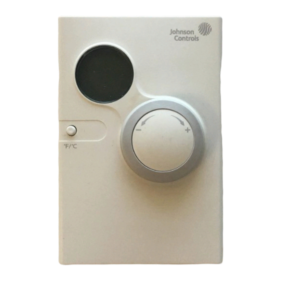
Surface-Mounted NS Series Network Sensors without LCD
Installation Instructions
NS-AHP7001-0, NS-AHN7001-x,
NS-ATN700x-x, NS-ATP700x-x
Applications
The surface-mounted NS Series Network Sensor
without Liquid Crystal Display (LCD) is an electronic
zone sensor designed to function directly with
Johnson Controls® BACnet®
Master-Slave/Token-Passing (MS/TP) digital
controllers in Heating, Ventilating, and Air Conditioning
(HVAC) systems. Models in this series monitor the
zone temperature and humidity, and transmit this data
to a field controller on the Sensor Actuator (SA) Bus.
A warmer/cooler dial is included on certain models for
minor temperature adjustments from the setpoint. An
occupancy override button is also featured on some
models, which allows the user to signal the controller
that the space is occupied, to request an override of
time-of-day scheduling. Rotation of the warmer/cooler
dial signals occupancy as well. Select models include
DIP switches to set a unique address in averaging
applications. Models are available with or without a
Johnson Controls logo on the face of the unit.
Depending on the model chosen, the wires connecting
the network sensor to the controller can be terminated
using either a modular jack or screw terminal block,
offering wiring flexibility.
Note: Models featuring a modular jack are not
intended for installations where daisy chaining to the
MS/TP Bus is required.
All models include an SA Bus access port for
connecting accessories to access the SA Bus. This
feature allows a technician to commission or service
the controller via the network sensor.
IMPORTANT: The surface-mounted NS Series
Network Sensor is intended to provide an input to
equipment under normal operating conditions.
Where failure or malfunction of the network sensor
could lead to personal injury or property damage to
the controlled equipment or other property,
additional precautions must be designed into the
control system. Incorporate and maintain other
devices, such as supervisory or alarm systems or
safety or limit controls, intended to warn of or protect
against failure or malfunction of the network sensor.
Surface-Mounted NS Series Network Sensors without LCD Installation Instructions
Refer to the
QuickLIT website
North American Emissions Compliance
United States
This equipment has been tested and found to
comply with the limits for a Class A digital device
pursuant to Part 15 of the FCC Rules. These limits
are designed to provide reasonable protection
against harmful interference when this equipment is
operated in a commercial environment. This
equipment generates, uses, and can radiate radio
frequency energy and, if not installed and used in
accordance with the instruction manual, may cause
harmful interference to radio communications.
Operation of this equipment in a residential area is
likely to cause harmful interference, in which case
the user will be required to correct the interference
at his/her own expense.
Canada
This Class (A) digital apparatus meets all the
requirements of the Canadian Interference-Causing
Equipment Regulations.
Cet appareil numérique de la Classe (A) respecte
toutes les exigences du Règlement sur le matériel
brouilleur du Canada.
Installation
Special Tools Needed
A 1/16 in. (1.5 mm) Allen wrench or a
Johnson Controls T-4000-119 Allen-Head Adjustment
Tool is required during installation.
Mounting
Location Considerations
Locate the network sensor:
•
on a partitioning wall, approximately 5 ft (1.5 m)
above the floor in a location of average
temperature
•
away from direct sunlight, radiant heat, outside
walls, outside doors, air discharge grills, or
stairwells; and from behind doors
Part No. 24-10094-17, Rev. J
Issued August 8, 2013
Supersedes December 16, 2011
for the most up-to-date version of this document.
1
Advertisement

Related Manuals for Johnson Controls NS-AHN7001 Series


Summary of Contents for Johnson Controls NS-AHN7001 Series
- Page 1 DIP switches to set a unique address in averaging Canada applications. Models are available with or without a Johnson Controls logo on the face of the unit. This Class (A) digital apparatus meets all the requirements of the Canadian Interference-Causing Depending on the model chosen, the wires connecting Equipment Regulations.
- Page 2 85°F (29°C) maximum dew point To mount the network sensor to the wall: 1. Use a 1/16 in. (1.5 mm) Allen wrench or Johnson Controls T-4000-119 Allen-Head Adjustment Tool to loosen the security screw on the top of the unit.
-
Page 3: Network Sensor Addressing
If the NS Series Network Sensor fails to operate within Controller Tool (FX-PCT) software to commission its specifications, replace the unit. For a replacement the network sensor. Refer to the Controller Tool network sensor, contact the nearest Johnson Controls Help (LIT-12011147) for more details. representative. Setup and Adjustments... -
Page 4: Technical Specifications
Technical Specifications Surface-Mounted NS Series Network Sensors without LCD (Part 1 of 2) Supply Voltage 9.8 to 16.5 VDC; 15 VDC Nominal (From SA Bus) Current Temperature 13 mA Maximum (Non-transmitting) Consumption Only Models Temperature 17 mA Maximum (Non-transmitting) and Humidity Models Terminations Modular Jack or Screw Terminal Block... - Page 5 The performance specifications are nominal and conform to acceptable industry standards. For application at conditions beyond these specifications, consult the local Johnson Controls office. Johnson Controls, Inc. shall not be liable for damage resulting from misapplication or misuse of its products.