Table of Contents
Advertisement
Advertisement
Table of Contents

Related Manuals for SME M2 Series


Summary of Contents for SME M2 Series
- Page 1 The best pick-up arm in the world INSTRUCTIONS SERIES M2 MODELS M2-9-10-12...
-
Page 2: Introduction
Introduction The Series M2 embraces three models the M2- 9, M2-10 and M2-12 offering pivot to stylus dimensions covering virtually all turntable requirements. These arms offer at reasonable cost meticulous build quality with all the most important features including lightweight stainless steel tonearm, detachable magnesium headshell with azimuth adjustment, tungsten balance weight, superb quality ball race bearings etc., and a level of... -
Page 3: Table Of Contents
Contents Page Introduction General arrangement Dimensions Specifications Packing list Parts identification Preparing the arm mounting board Fitting the arm Audio lead Fitting the cartridge Fitting the headshell Longitudinal balance Vertical tracking force (VTF) adjustment Arm height (VTA) adjustment Azimuth adjustment Horizontal tracking angle (HTA) adjustment Positioning the armrest Anti-skate adjustment... -
Page 4: General Arrangement
General arrangement: M2-9, M2-10 & M2-12... -
Page 5: Dimensions
Dimensions M2-9 M2-10 M2-12 Pivot to stylus 233.20 239.30 308.81 Pivot to turntable centre 215.40 222.00 295.60 Cartridge fixing centres 12.70 12.70 12.70 Offset Angle 23.63º 23.23º 17.62° Linear offset 93.47 93.47 93.47 Overhang 17.80 17.30 13.21 Height above mounting surface 87.00 max 87.00 max 87.00 max 63.00 min 63.00 min... -
Page 6: Specifications
Specifications M2-9 M2-10 M2-12 Effective mass (g) 9.50 9.60 12.00 Cartridge balance range (g) 5-12 5-12 5-12 Vertical tracking force (VTF) 0-2.5 0-2.5 0-2.5 Maximum tracking error (degree/mm) 0.013 0.013 0.010 Null points: Inner (mm radii) 66.04 66.04 66.04 Outer 120.90 120.90 120.90... -
Page 7: Packing List
Packing list The pack is the only one in which your Series M2 precision pick-up arm can be safely transported. Please keep it for possible future use. It contains the following: Series M2 precision pick-up arm. Detachable headshell. Instruction book. Mounting template. -
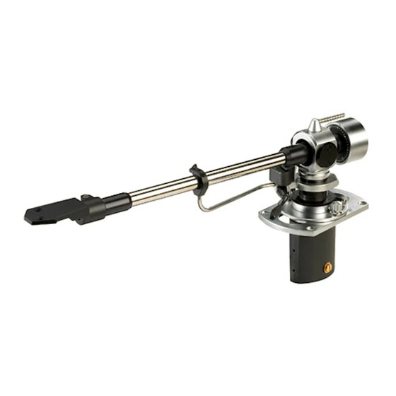
Page 8: Parts Identification
Parts identification Anti-skate Guide Anti-skate Weight Illustration shows arm fitted with FD-M2 Fluid Damper. Balance Weight Dip-Screw & Locknut Damper Cover Anti-Skate Lever Damper Bath Arm Lift Bedplate VTF Indicator Label Arm Rest Shield Can VTA Thumbwheel Tone-Arm Pillar Clamp Screw Headshell Clamp Bolt Mounting Washer... -
Page 9: Preparing The Arm Mounting Board
Disengage the template from the spindle and Using a scriber or a compass point, spike SME arm, it will need to be prepared as follows: maintaining the same alignment slide it down through the centre points B and centres of the the pin and onto the mounting board. -
Page 10: Fitting The Arm
104 Fitting the arm Remove the inner base clamp nut and base Fit a mounting washer to each of the four Position the arm on the mounting board and clamp washer. Pass the loop at the lower end counterbores in the upper surface of the insert the M3 button head screws into the holes. - Page 11 MC HEAD AMP/TRANSFORMER PRE-AMP/CONTROL UNIT NOTE: Connection should be made between L PHONO R PHONO R the ground terminals of the deck and pre-amp unless a path already exists. CONNECT TO PRE-AMP GROUND 107 Audio Lead The illustration shows use with and without a head amp/transformer and phono plug connections should be made accordingly. Connect the ground wire serving the arm to the pre-amp ground, and those from the rear of the phono plugs to the ground terminal on the piece of equipment to which these plugs are connected.
-
Page 12: Fitting The Cartridge
108 Fitting the cartridge See 113 - Removing the headshell. Most cartridges have their own screws. Examine the top of the cartridge. It is important Before fitting the cartridge see that the stylus We provide one pair #3-48 UNC x 11mm with that it presents a good flat face to the underside guard (not illustrated) is in position as a nuts and washers, other lengths are available... -
Page 13: Fitting The Headshell
BLUE GREEN WHITE 111 Cartridge lead replacement 112 Fitting the headshell 113 Removing the headshell The cartridge leads. Part No. 1806, can be Using the 2mm A/F wrench release the Using the 2mm A/F wrench release the clamp replaced and may be obtained from your dealer headshell clamp bolt and remove it. -
Page 14: Longitudinal Balance
114 Longitudinal balance Position the arm so that it is clear of the armrest Adjust until the arm, with cartridge fitted, is either level or slightly low at the front end. and the cartridge is clear of the turntable. Move the control lever into the lowered position. -
Page 15: Vertical Tracking Force (Vtf) Adjustment
116 Vertical Tracking Force (VTF) Adjustment VTF is set after longitudinal balancing has been The indicator on the front face of the weight For safety the lever of the lowering control completed, see 114. carries the letters A-B-C-D at quarter turn should now be moved into the raised position. -
Page 16: Arm Height (Vta) Adjustment
119 Arm Height (VTA) Adjustment Release the pillar clamp screw, using the 2mm Use an old but unwarped record for the Re-position the alignment protractor about 6mm A/F wrench, by one turn only. following procedures in case of accidental from the edge of the record. Using the right- damage. -
Page 17: Azimuth Adjustment
122 Azimuth adjustment Place a small mirror on the turntable and rest Release the headshell clamp bolt by one Re-check with the mirror and when satisfied the stylus on it. Viewed in this way any quarter turn, see 113. The stylus must be clear tighten the headshell clamp bolt firmly with the departure from vertical is accentuated and of the mirror whilst this is done. -
Page 18: Horizontal Tracking Angle (Hta) Adjustment
125 Horizontal tracking angle (HTA) adjustment With a record on the turntable, place the Most cartridges have a stylus – fixing hole Place the tonearm into the armrest and release alignment protractor onto the record spindle. dimension of 9.5mm. With these, the outlines of the two base clamp nuts, using a snugly fitting Check that the VTF has been set to suit the the tonearm and protractor will coincide when... -
Page 19: Positioning The Armrest
128 Positioning the armrest Release the pillar clamp screw using the 2mm Rotate the pillar to position the armrest conveniently in relation to the turntable. The dimension ‘X’ A/F wrench. should not be more than 75mm or less than 25mm. Tighten the pillar clamp screw firmly, avoiding excessive force. - Page 20 130 Anti-skate adjustment Thread the filament through the guide pulley Drop the loop into the groove corresponding to Loosen the inner base clamp nut enough to housing and pass the loop over the anti-skate the vertical tracking force being used. allow movement of the anti-skate guide.
-
Page 21: Operation
133 Operation Rotate the control lever fully, in the direction of Position the arm so that the stylus is over the To lower the stylus onto the record move the the arrow, and move the tonearm out from the selected track of the record. control lever forwards, in the direction of the armrest. - Page 22 136 Operation (continued) 137 Adjusting height of lift 138 Cleaning the arm lift To raise the stylus from the record move the The raising and lowering control is set to suit If the arm drifts outwards during raising or control lever back to its original position. When the majority of cartridges but the height raised lowering it indicates contaminant on the rubber the arm is not in use it should always be...
-
Page 23: Appendix
Appendix We hope these instructions have made the installation your Series precision pick-up straightforward. Care for it as you would a camera. Do not apply oil or other lubricant to any part of it. Do not attempt to take it to pieces or interfere with any of the screws except as directed in the instructions. - Page 24 MANUFACTURED BY ∙ SME LTD ∙ STEYNING ∙ SUSSEX ∙ BN44 3GY ∙ ENGLAND +44 (0)1903 814321 ∙ +44 (0)1903 814269...
Need help?
Do you have a question about the M2 Series and is the answer not in the manual?
Questions and answers