Table of Contents
Advertisement
Instruction Manual and
Experiment Guide for
the PASCO scientific
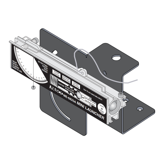
Model ME-6825A
MINI LAUNCHER
W E
A R
S A
F E
G L
A S
W H
E N
D O
N O
T P
T Y
U S
P I S
H
S E
T O
S
N
W I
I N
F I N
T H
U S
G E
T h
E .
R !
i r d
L o
C l i
n g
c k
R a
n g
e
0
S e
c o n
M e
d i u
C A
U T
I O N
D O
!
D O
M E
d C
l i c k
m R
a n g
e
F i r
s t C
S h
l i c k
o r t
R a
n g
N O
e
T L
U s
W N
O O
e 1
B A
K
6 m
R R
m s
E L
.
t e e
l b a
- 6 8
l l s
P u
O N
s h
2 5
L Y !
w i t
h P
A
U n
t i l P
e n
o r
i s t o
R o
n C
d
l i c k
L a
s
u n
c h
P o
s i t
i o n
o f
B a
l l
012-09562A
Advertisement
Table of Contents

Summary of Contents for PASCO MINI LAUNCHER ME-6825A
- Page 1 012-09562A Instruction Manual and Experiment Guide for the PASCO scientific Model ME-6825A MINI LAUNCHER P I S F I N i r d C l i c o n d i u l i c k a n g F i r...
-
Page 2: Table Of Contents
012-09562A Mini Launcher Table of Contents Section Page Introduction ....................... 1 Equipment ......................2 General Operation Of The Mini Launcher ............3 Installation Of The Optional Photogate Bracket ..........4 Installing the 2-Dimensional Collision Attachment ..........5 Expectations For The Mini Launcher ..............5 Launch Positions .................... -
Page 3: Introduction
012-09562A Mini Launcher Introduction The PASCO Mini Launcher has been designed for • FIXED ELEVATION INDEPENDENT OF projectile experiments and demonstrations. The only ANGLE: additional equipment required is a C-clamp or m steel balls ONLY! ME-9376B Universal Table Clamp for clamping the Ball Launcher to a table. -
Page 4: Equipment
Mini Launcher 012-09562A Equipment The ME-6825 Mini Launcher includes the following: • Launcher and Base (Assembled) • (2) 16mm Steel Balls • String (to pull trigger) Safety Goggles • Collision Attachment • Safety Goggles • Pushrod • Manual Launcher Trigger Collision Attachment P I S F I N... -
Page 5: General Operation Of The Mini Launcher
012-09562A Mini Launcher General Operation of the Mini Launcher ➀ Ready - Always wear safety goggles when you are in a - Place the ball in the barrel. Push the ball down the room where the Mini Launcher is being used. barrel with the pushrod until the trigger catches the piston. -
Page 6: Installation Of The Optional Photogate Bracket
Mini Launcher 012-09562A Installing the Optional Photogate Bracket (ME-6821) The Photogate Bracket is an optional accessory for vided with the photogates. mounting one or two photogates on the Mini ➁ To mount the bracket to the Launcher, align the Launcher to measure the muzzle velocity of the ball. square nut in the slot on the bottom of the Installation is as follows: Launcher and slide the nut into the slot. -
Page 7: Installing The 2-Dimensional Collision Attachment
012-09562A Mini Launcher Installing the 2-Dimensional Collision Attachment The two dimensional Collision Attachment consists of Square 2 screws, 2 nuts, and a flat plastic bar. It is used with the Mini Launcher to hold a second ball in front of the muzzle so the launched ball will collide with the second ball, creating a 2-dimensional collision. -
Page 8: Launch Positions
Mini Launcher 012-09562A Launch Positions Clamp base to table. Mount launcher as shown to shoot onto table. The square nut that the Launcher pivots around should be slid to the front of the launcher. Ball is launched at table level. When you change the angle of the launcher, the launch position does not change. -
Page 9: Experiments 1. Projectile Motion
012-05479B Mini Launcher Experiment 1: Projectile Motion EQUIPMENT NEEDED: – Mini Launcher and steel ball – Plumb bob – Meter stick – Carbon paper – White paper Purpose The purpose of this experiment is to predict and verify the range of a ball launched at an angle. The initial velocity of the ball is determined by shooting it horizontally and measuring the range Figure 1.1: Setup to shoot... - Page 10 Mini Launcher 012-05479B Procedure Part A: Determining the Initial Velocity of the Ball ➀ Put the ball into the Mini Launcher and cock it to the long range position. Fire one shot to locate where the ball hits the floor. At this position, tape a piece of white paper to the floor.
- Page 11 012-05479B Mini Launcher (Total Average Distance = Distance to paper edge + Average Distance) Part B: Predicting the Range of the Ball Shot at an Angle ➀ Adjust the Mini Launcher to launch at an angle between 20 and 60 degrees above the horizontal. Record this angle in Table 1.2.
- Page 12 Mini Launcher 012-05479B Part C: Predicting the Range of the Ball Shot at a Negative Angle ➀ Adjust the Mini Launcher to launch at an angle between 10 and 40 degrees below the horizontal and record this angle in Table 1.3. ➁...
-
Page 13: Projectile Motion Using Photogates
012-05479B Mini Launcher Experiment 2: Projecile Motion Using Photogates EQUIPMENT NEEDED – Mini Launcher and steel ball – Photogate bracket – (2) Photogates – Computer and Timing software – Plumb bob – Meter stick – Carbon paper – White paper Purpose The purpose of this experiment is to predict and verify the range of a ball launched at an angle. - Page 14 Mini Launcher 012-05479B Procedure PART A: Determining the Initial Velocity of the Ball ➀ Put the steel ball into the Mini Launcher and cock it to the long range position. ➁ Run the timing program and set it to measure the time it takes the ball to pass through both photogates.
- Page 15 012-05479B Mini Launcher Table 2.2 Confirming the Predicted Range Angle above or below horizontal = ______________ Horizontal distance to paper edge = ____________ Calculated time of flight= ____________ Predicted Range = ____________ Trial Number Distance from Edge of Paper Average Total Average Distance Analysis ➀...
- Page 16 Mini Launcher 012-05479B Notes ®...
-
Page 17: Projectile Range Versus Angle
012-05479B Mini Launcher Experiment 3: Projectile Range Versus Angle EQUIPMENT NEEDED – Mini Launcher and steel ball – Plumb bob – Measuring tape or meter stick – Carbon paper – Graph paper – White paper Purpose The purpose of this experiment is to find how the range of the ball depends on the angle at which it is launched. - Page 18 Mini Launcher 012-05479B where y is the initial height of the ball and y is the position of the ball when it hits the floor. Setup ➀ Clamp the Mini Launcher near one end of a sturdy table with the Launcher aimed so the ball will land on the table.
- Page 19 012-05479B Mini Launcher ➄ Increase the angle by 10 degrees and repeat all the steps. ➅ Repeat for angles up to and including 80 degrees. SHOOTING OFF THE TABLE Clamp the Mini Launcher as shown in Fig 3.4 so that the ball will hit the floor.
- Page 20 Mini Launcher 012-05479B Notes ®...
-
Page 21: Projectile Path
012-05479B Mini Launcher Experiment 4: Projectile Path EQUIPMENT NEEDED – Mini Launcher and steel ball – Measuring tape or meter stick – Carbon paper – White paper – Movable vertical target board (Must reach from floor to muzzle) – Graph paper Purpose The purpose of this experiment is to find how the vertical distance the ball drops is related to the horizon- tal distance the ball travels when launched horizontally from a table. - Page 22 Mini Launcher 012-05479B (carbon side down) over the white paper. Procedure ➀ Measure the vertical height from the floor to the muzzle and record in Table 4.1. Mark this height on the target. ➁ Measure the horizontal distance from the muzzle of the Mini Launcher to the target and record in Table 4.1.
- Page 23 012-05479B Mini Launcher Table 4.2 Initial Speed Slope of graph Initial speed from slope Time of flight Initial speed from x, y Percent Difference Questions ➀ Was the line straight? What does this tell you about the relationship between y and x? ➁...
- Page 24 Mini Launcher 012-05479B Notes ®...
-
Page 25: Conservation Of Energy
012-05479B Mini Launcher Experiment 5: Conservation of Energy EQUIPMENT NEEDED – Mini Launcher and steel ball – Plumb bob – Measuring tape or meter stick – White paper – (optional) 2 Photogates and Photogate Bracket – Carbon paper – (optional) Timing System Purpose The purpose of this experiment is to show that the kinetic energy of a ball shot straight up is transformed into potential energy. - Page 26 Mini Launcher 012-05479B PART I: Determining the Initial Velocity of the Ball (without photogates) ➀ Put the steel ball into the Mini Launcher and cock it to the chosen range position. Fire one shot to locate where the ball hits the floor. At this position, tape a piece of white pa- per to the floor.
- Page 27 012-05479B Mini Launcher ALTERNATE METHOD FOR DETERMINING THE INITIAL VELOCITY OF THE BALL (US- ING PHOTOGATES) ➀ Attach the photogate bracket to the Launcher and attach two photogates to the bracket. Plug the photogates into a computer or other timer. ➁...
- Page 28 Mini Launcher 012-05479B Table 5.3 Results Maximuim Height of Ball Mass of Ball Initial Kinetic Energy Final Potential Energy Percent Difference Questions ➀ How does friction affect the result for the kinetic energy? ➁ How does friction affect the result for the potential energy? ®...
-
Page 29: Conservation Of Momentum In Two Dimensions
012-05479B Mini Launcher Experiment 6: Conservation of Momentum In Two Dimensions EQUIPMENT NEEDED – Mini Launcher, 2 steel balls and Collision Attachment – Plumb bob – Meter stick – Protractor – Butcher paper – Tape to make collision inelastic – Stand to hold ball –... - Page 30 Mini Launcher 012-05479B Setup ➀ Clamp the Mini Launcher near one end of a sturdy table with the Launcher aimed inward toward the table. Mount the launcher in the top hole of the bracket. ➁ Adjust the angle of the Mini Launcher to zero degrees so the ball will be shot off horizontally onto the table.
- Page 31 012-05479B Mini Launcher PERFORM THE FOLLOWING THREE STEPS FOR THE ELASTIC COLLISION AND THEN REPEAT THESE THREE STEPS FOR THE INELASTIC COLLISION: ➃ For the x-direction, check that the momentum before equals the momentum after the collision. To do this, use the lengths for the momentums and calculate the x-components using the angles.
- Page 32 Mini Launcher 012-05479B Notes ®...
-
Page 33: Varying Angle To Maximize Height On A Wall
012-05479B Mini Launcher Experiment 7: Varying Angle To Maximize Height on a Wall EQUIPMENT NEEDED – Mini Launcher and steel ball – Plumb bob – Measuring tape or meter stick – Carbon paper – White paper – Board to protect wall Purpose The purpose of this experiment is to find the launch angle which will maximize the height at which the ball strikes a vertical wall for a ball launched at a fixed horizontal distance from the wall. - Page 34 Mini Launcher 012-05479B ➃ Tape a piece of white paper to the board in the region where the ball is hitting. Then cover the white paper with a piece of carbon paper. Procedure ➀ Shoot the ball at various angles and pinpoint exactly which angle gives the maximum height by checking the marks on the paper.
-
Page 35: Demo: Do 30° And 60° Give Same Range
012-05479B Mini Launcher Experiment 8 (Demo): Do 30 ⋅ ⋅ ⋅ ⋅ ⋅ and 60 ⋅ ⋅ ⋅ ⋅ ⋅ Give the Same Range? EQUIPMENT NEEDED -Mini Launcher and steel ball Purpose The purpose of this demonstration is to show that the range of a ball launched at 30° is the same as one launched at 60°... -
Page 36: Demo: Simultaneously Shoot Two Balls Horizontally At Different Speeds
Mini Launcher 012-05479B Experiment 9 (Demo): Simultaneously Shoot Two Balls Horizontally at Different Speeds EQUIPMENT NEEDED – 2 Mini Launchers and 2 steel balls Purpose The purpose of this demonstration is to show that regardless of the initial speed of the balls launched horizontally off a table, the balls will hit the floor at the same time. -
Page 37: Demo: Shooting Through Hoops
012-05479B Mini Launcher Experiment 10 (Demo): Shooting Through Hoops EQUIPMENT NEEDED – Mini Launcher and steel ball – (5) Ring clamps on stands – (2) Photogates – Photogate Bracket – Meter stick – (2) Meter stick – (optional) Computer with Timing software Purpose The purpose of this demonstration is to show that the path of a ball launched horizontally from a table is parabolic. - Page 38 Mini Launcher 012-05479B ➂ Lay the 2-meter stick on the floor in a straight line away from the Launcher. ➃ Measure off each set of x and y and place a ring clamp on a stand at each position (See Figure 10.1).
-
Page 39: Technical Support
Reproduction under any other circumstances, without the written consent of PASCO scientific, is prohibited.
Need help?
Do you have a question about the MINI LAUNCHER ME-6825A and is the answer not in the manual?
Questions and answers