
Related Manuals for Teknim TFP-121 Series


Summary of Contents for Teknim TFP-121 Series
- Page 1 TFP-121x Series Analogue Addressable Fire Alarm Control Panel Installation & Operating Manual Issue Date : 25/08/2017 Rev:00...
-
Page 2: Table Of Contents
TFP-121x Series Analogue Addressable Fire Alarm Control Panels Table of Contents Introduction ............................. 4 Warnings ..............................4 Technical Specifications ..........................5 TFP-121x Series Analogue Addressable System.................... 6 Panel Properties ..........................6 Panel User Interface .......................... 7 Installation ............................... 9 Recommended Cables ........................9 Installation ............................ - Page 3 TFP-121x Series Analogue Addressable Fire Alarm Control Panels 7.1.1 Fire Window ..........................22 7.1.2 Error Window ..........................23 7.1.3 Warning Window ........................24 Event Log ............................25 Disable Menu ..........................27 7.3.1 Disabled Devices ......................... 27 7.3.2 Disabled Zones ........................... 27 7.3.3 Disabled Sirens ...........................
- Page 4 TFP-121x Series Analogue Addressable Fire Alarm Control Panels Table 1 : User Interface Button Functionality Table………………………………………………………………………………….…………………. Table 2 - LED Indicators………………………………………………………………………………………………………………………..…………………. Table 3 : Recommended Cable Specifications…………………………………………………………………………………………..…………………. Table 4 - Loop Card DIP Switch Address Setting…………………………………………………………………………………………………………. Table 5 : Level Timeout Periods……………………………………………………………………………………………………………..…………………. Table 6 - TCP/IP Default Values……………………………………………………………………………………………………………..………………….
-
Page 5: Introduction
Teknim Analogue Addressable Panels. TFP-121x Teknim analogue addressable panels can be handled within two optional categories as those supporting 1 loop or 2 loops. Up to 240 devices can be employed per loop in TFP-121x series panels and all these devices operate through Teknim Flashlink protocol. -
Page 6: Technical Specifications
TFP-121x Series Analogue Addressable Fire Alarm Control Panels Technical Specifications Power supply Voltage 220 / 110 VAC (+%10 / -%15) Frequency 50 / 60 Hz (±%5) Mains Input Fuse Output Voltage 21 – 29 VDC ± %2 Output Fuse 6A (F1) Cable Type 3 x 1,5mm²... -
Page 7: Tfp-121X Series Analogue Addressable System
Configuration Software. In addition to this, panel access through internet connection, and monitoring facility through the Teknim Fire Detection System Monitoring Software are also provided. The Teknim Addressable Fire Detection System Configuration Software provides technical teams with ease of use for the configuration process. -
Page 8: Panel User Interface
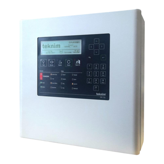
TFP-121x Series Analogue Addressable Fire Alarm Control Panels Panel User Interface This chapter describes the indicators and buttons on the panel. Figure 10 : Control Panel User Interface The letters displayed in the Figure 1 : Control Panel User Interface are respectively listed below. Table 1 : User Interface Button Functionality Table Label Function... - Page 9 TFP-121x Series Analogue Addressable Fire Alarm Control Panels It includes input, confirm, save and similar functionality. Used to enter menu in the main screen. if kept pressed for a long time on the main screen password entry window will open or switch to Level-1 Numbers 0-9.
-
Page 10: Installation
TFP-121x Series Analogue Addressable Fire Alarm Control Panels Installation This section describes the mechanical and electrical connection techniques of TFP-121x series panels. Caution: Do not start installation until you have read all of this entire manual! Recommended Cables It is recommended to employ the cables specified in the "Table 3: Recommended Cable Specifications" for wiring installations and all electrical connections. -
Page 11: Watch Battery
Loop Expansion Card Connection TFP-121x Teknim analogue addressable panels support 2 loops. In order to add a new loop card to a single loop panel; Make sure that there is no power on the panel in the first place. -
Page 12: Class A Loop Connection
The connection form of the loop line and devices (Class A) is shown in “9.2 Appendix-Electrical / Figure 36 : Loop Connection”. The unused loop line must be deactivated through the panel or using the "Teknim Loop Configuration" software. If there is no connection made to the loop, the panel will issue a "Loop X Open Circuit" error. -
Page 13: Configuration
TFP-121x Series Analogue Addressable Fire Alarm Control Panels Configuration This section contains information on the configuration and use of the fire detection system. Panel Activation Activation is a process that enables access to the programming menu for the first installation of the addressable fire detection system. -
Page 14: Level 3
Establish the connection with the computer as shown in “9.4 Appendix-Level / Figure 40 : PC Ethernet Connection” and run the "Teknim Addressable Fire Detection System Configuration Software". Teknim recommends the use of "Teknim Addressable Fire Detection System Configuration Software" in order to get the best result for the installation of fire system. -
Page 15: Tcp/Ip Configuration
Applicable panel configuration files can be downloaded, edited, stored, • Advanced level scenario rules can be created. Information on the use of the software can be found in the "Teknim Addressable Fire Detection System Configuration Software" document. 6.3.1 TCP/IP Configuration TCP / IP configuration is required to be done in order to use "Teknim Addressable Fire Detection System... -
Page 16: Panel Configuration Sequence
TFP-121x Series Analogue Addressable Fire Alarm Control Panels Table 8 : Default Device Parameters Device Parameters Value Type Zone Label [Device xxx] Night Sensitivity High Day Sensitivity High Disabled Table 9 : Default Loop Parameters Loop Parameters Value Label [Loop xx] Active Yes (No, for 1-loop panels) Disabled... -
Page 17: Panel Parameter Settings
TFP-121x Series Analogue Addressable Fire Alarm Control Panels Select “Menu » Programming » Date and Time Settings”, Navigate forms using arrow keys, Go to the form to be changed and press "OK", Use arrow keys to enter a new value and press "OK" key, Press "ESC"... -
Page 18: General Delay Setting
TFP-121x Series Analogue Addressable Fire Alarm Control Panels Select one of the language options and press "OK" again. 6.4.4.4 Loop Devices Status LED All loop devices will initially turn on and off the status LEDs at 20 second intervals as default. If this status LED is required to be changed, then;... -
Page 19: Zone Based Delay Setting
Configuration through Panel ”. How to add the devices which have been addressed and connected to the loop line, to the system will be told under this heading. Teknim TFP-121x series panels can do the procedure for adding devices very simply and quickly. For addition of new devices, refer to “7.9.4. Add Device”. -
Page 20: Device Parameters
TFP-121x Series Analogue Addressable Fire Alarm Control Panels 6.4.8 Device Parameters The parameters of the new devices added in the previous step are configured in the same way as the values in the following table; “Table 8 : Default Device Parameters”. Only the device type value received from the newly added devices is changed during the loop query. - Page 21 TFP-121x Series Analogue Addressable Fire Alarm Control Panels Select a module equipped with “Input” feature and press “OK” key, Select “Input Activation” form and select one of such values “Alarm”, “Evacuate”, “Reset”, “Mute”, “Error”, “Scenario”, Press first “OK” then “ESC” key. 6.4.8.5 Type of Monitoring Type of monitoring is a parameter that is valid only in modules with input capability (Input Module, Input/Output Module with External Supply, Dry Contact Input-Output Module).
-
Page 22: Zone Parameters
TFP-121x Series Analogue Addressable Fire Alarm Control Panels Zone Siren : Output modules are pulled at the end of the delay time when a fire in their own zone occurs or when the evacuation is activated. It does not restore until the "Reset" or "Mute" key is pressed. Zone Error : In case of any error in their own zone the output modules are pulled. -
Page 23: Using The Panel
TFP-121x Series Analogue Addressable Fire Alarm Control Panels Using the Panel In this section you will find information about using the panel and other features of the panel. Status Window The status window is the message window showing the "Fire", "Error" and "Warning" messages related to the instantaneous operational data of the panel. -
Page 24: Error Window
TFP-121x Series Analogue Addressable Fire Alarm Control Panels 7.1.2 Error Window Errors are the types of data that will affect the direct functioning of critical functions such as fire detection/notification on the system. In order to access error list, select "Errors" in the "STATUS" window and press "OK"... -
Page 25: Warning Window
TFP-121x Series Analogue Addressable Fire Alarm Control Panels The two terminals of the siren line were short-circuited. 10 Device [X] N/A The device may be removed, defective, or remained in the open circuit section of the loop. Such error will also be seen in case the excess current is drawn through the loop line. -
Page 26: Event Log
Scenario rules becoming effective Event Log The event log is the section where situations that are important to the Teknim addressable panel are recorded and displayed. In the event log, records are divided into 10 categories and each category is evaluated with different events within itself. - Page 27 TFP-121x Series Analogue Addressable Fire Alarm Control Panels Table 14 - Event Log Categories Category Event Devices Alarm Smoke Alarm Heat Alarm Smoke & Heat Alarm Button Alarm Input Module Alarm Device N/A Device Configured CRC Error Short Circuit Open Circuit Load Error External Supply Error Type Error...
-
Page 28: Disable Menu
TFP-121x Series Analogue Addressable Fire Alarm Control Panels Disable Menu Disable menu is used to put devices, zones, siren outputs and loop lines into the "Disabled" state. 7.3.1 Disabled Devices Deactivated devices continue to communicate with the panel, but do not participate in the process of a fire situation. The fire detection process continues when the disabled state is removed from the device. -
Page 29: Disabled Loops
TFP-121x Series Analogue Addressable Fire Alarm Control Panels Go to the “Menu » Disable » “Disabled Outputs” menu, Select the required output from the list and change the status into “PASSIVE”, Change the output status into “ACTIVE” if you want to reactivate the output. Figure 24 - Disabled Sirens Window 7.3.4 Disabled Loops... -
Page 30: Device Led Test
TFP-121x Series Analogue Addressable Fire Alarm Control Panels Figure 26 - Zone Test Settings Window Device LED Test The device LED test is used in cases where a need is arisen to determine the address/place of the devices or to check whether the communication is healthy. -
Page 31: Loop Control
TFP-121x Series Analogue Addressable Fire Alarm Control Panels 7.9.2 Loop Control This function is used to determine the location of discontinuities in the loop line. For this: Go to “Menu » Programming » Loop Functions » Loop Control” menu, Press “OK” key in order to perform loop control, The loop control scans the entire line and determines the number of devices detected on the part of "Loop Output"... -
Page 32: Delete Device
TFP-121x Series Analogue Addressable Fire Alarm Control Panels 7.9.5 Delete Device In order for a device to be deleted from the loop, such device must be removed from the loop in the first place and there must be an error message notifying that the device is missing. Assuming that the foregoing conditions are met, for deleting a device: Go to “Menu »... -
Page 33: Tdnet Functions
TdNET is a multi-master protocol and communication technology that works with Token-Passing topology that provides the network infrastructure of Teknim addressable fire detection systems. A network is created with up to 16 devices supporting the TdNET protocol. In order to connect the TFP-121x panels to the network line, the TFC-1208 TdNET Network Card must be integrated through the P2 port on the motherboard. -
Page 34: Incoming Commands
TFP-121x Series Analogue Addressable Fire Alarm Control Panels Event Memory : can be selected as ACTIVE/PASSIVE. It is specified that whether the data received from the network will be recorded in the event log. Time Synchronization : can be selected as Local/Network. The time and date settings are achieved through the network or provided locally. -
Page 35: Users
TFP-121x Series Analogue Addressable Fire Alarm Control Panels Figure 32 - TdNET Outgoing Commands 7.11 Users The TFP-121x panels have a total of 7 users. All users can be set as level 2 and level 3 users and can be selected as active/passive. -
Page 36: Service Warning
TFP-121x Series Analogue Addressable Fire Alarm Control Panels 7.12 Service Warning The panel has a feature that gives a service warning on a specified date. In order to set the service time: Go to “Menu » Programming » Service” menu, In order to activate the service warning feature, change the "Service Error"... -
Page 37: Conditions Requiring Maintenance, Repair, Or Servicing
TFP-121x Series Analogue Addressable Fire Alarm Control Panels Conditions requiring Maintenance, Repair, or Servicing Maintenance and repair of the analogue addressable fire alarm systems must be carried out by authorized personnel in accordance with the instructions. In the event of any malfunction or in any of the following situations, please contact your authorized service or your dealer. - Page 38 TFP-121x Series Analogue Addressable Fire Alarm Control Panels Each week, a normally operating alarm button should be activated and if there is any problem in the fire detection and alarm system of the panel, this problem must be noted down. Tests should be performed on the same day of the week and a different alarm button should be used for each test.
-
Page 39: Appendices
TFP-121x Series Analogue Addressable Fire Alarm Control Panels Appendices Appendices are divided into 4 categories as Mechanical, Electrical, Menu and Level. Appendix-Mechanical Figure 36 : Panel Front Cover Screws TFP-121X INSTALLATION AND OPERATION MANUAL... - Page 40 TFP-121x Series Analogue Addressable Fire Alarm Control Panels Figure 37 : Mounting Screw Holes TFP-121X INSTALLATION AND OPERATION MANUAL...
- Page 41 TFP-121x Series Analogue Addressable Fire Alarm Control Panels Figure 38 : Electrical Connections TFP-121X INSTALLATION AND OPERATION MANUAL...
- Page 42 TFP-121x Series Analogue Addressable Fire Alarm Control Panels Figure 39 : Battery Connection • Battery brackets marked with B1 are fixed through the screw locations • B3 and B5 are connected with battery jumper cable • B2 and B4 are connected to the battery supply socket with the battery supply cable TFP-121X INSTALLATION AND OPERATION MANUAL...
- Page 43 TFP-121x Series Analogue Addressable Fire Alarm Control Panels Figure 40 - Loop Card, Network Card and Repeater Panel Connection Points TFP-121X INSTALLATION AND OPERATION MANUAL...
- Page 44 TFP-121x Series Analogue Addressable Fire Alarm Control Panels Figure 41 - TFC-1201 Network Card TFP-121X INSTALLATION AND OPERATION MANUAL...
- Page 45 TFP-121x Series Analogue Addressable Fire Alarm Control Panels Figure 42 - TFC-1201 Loop Card TFP-121X INSTALLATION AND OPERATION MANUAL...
-
Page 46: Appendix - Electrical
TFP-121x Series Analogue Addressable Fire Alarm Control Panels Appendix – Electrical Figure 43 : RTC Battery Connection TFP-121X INSTALLATION AND OPERATION MANUAL... - Page 47 TFP-121x Series Analogue Addressable Fire Alarm Control Panels Figure 44 : Sounders Connection Figure 45 : Loop Connection TFP-121X INSTALLATION AND OPERATION MANUAL...
-
Page 48: Appendix - Menu
TFP-121x Series Analogue Addressable Fire Alarm Control Panels Appendix – Menu Figure 46 : Level 1 Menu Flow 01.Logs Log Page Log Page 2 Main Menu … Log Page N 02.Enter TFP-121X INSTALLATION AND OPERATION MANUAL... - Page 49 TFP-121x Series Analogue Addressable Fire Alarm Control Panels Figure 478 : Level 2 Menu Flow 01.Logs Log Page Log Page 2 … Log Page N 02.Settings Mode: Auto/Night/Day General Delay: ON / OFF 03.Time Set Time 04.Contact Info Adress, Company Name, Phone number, e-mail 05.Disablements 01.Devices Disablement...
- Page 50 TFP-121x Series Analogue Addressable Fire Alarm Control Panels Figure 489 : Level 3 Menu Flow 01.Logs Log Page Log Page 2 … Log Page N 02. Settings Mode: Auto/Night/Day General Delay: ON / OFF 03.Time Set Time 04.Contact Info Adress, Company Name, Phone number, e-mail 05.Disablements 01.Devices Disablement...
- Page 51 TFP-121x Series Analogue Addressable Fire Alarm Control Panels Time: NN:NN General Delay : ON/OFF 02.Zone Based Delay Zone: [0-72] Delay: GENERAL/ZONAL time : 00:00 04.Panel Status Power: xx.x VDC Bat. : zz.z VDC Temp. : aa C SYST.: yy.y VDC SNDR.1: bb.b VDC SNDR .2: bb.b VDC Main Board Ver.:...
- Page 52 TFP-121x Series Analogue Addressable Fire Alarm Control Panels Monday: XX:XX, YY:YY Tuesday: XX:XX, YY:YY Wednesday: XX:XX, YY:YY Thursday: XX:XX, YY:YY Friday: XX:XX, YY:YY Saturday: XX:XX, YY:YY Sunday: XX:XX, YY:YY 07. Loop Functions Device List Loop Check O:xxx, I:xxx Loop Info EMP: XXX SHD: XXX HD: XXX...
- Page 53 TFP-121x Series Analogue Addressable Fire Alarm Control Panels Disablement: NO/Yes 08.TdNET Functions TdNET Map Panel 1-16: ENAB./DIS. TdNET Parameters TdNET Mode: Station / Main Panel / Standalone Logging: ENAB./DIS. Time Sync : Network / Local Night/Day: Network / Local Delays: ENAB./DIS. Wiring: ClassA /ClassB Outgoing Commands Alarm : ENAB./DIS.
-
Page 54: Appendix - Pc Connection
TFP-121x Series Analogue Addressable Fire Alarm Control Panels Appendix – PC Connection Figure 49 : PC Ethernet Connection TFP-121X INSTALLATION AND OPERATION MANUAL... -
Page 55: Appendix - En 54 Standard
TFP-121x Series Analogue Addressable Fire Alarm Control Panels Appendix - EN 54 Standard TFP-121x Alarm panels are designed in compliance with EN 54-2 and EN 54-4 standards. In addition, the following EN 54-2 optional functions are also available. Table 16 - EN 54-2 Optional Functions Function Definition Output for fire alarm devices... -
Page 56: Appendix - Maintenance Table
TFP-121x Series Analogue Addressable Fire Alarm Control Panels Appendix - Maintenance Table Date Tested Device Device Location Explanation TFP-121X INSTALLATION AND OPERATION MANUAL... - Page 57 TFP-121x Series Analogue Addressable Fire Alarm Control Panels Date Tested Device Device Location Explanation TFP-121X INSTALLATION AND OPERATION MANUAL...
- Page 58 TFP-121x Series Analogue Addressable Fire Alarm Control Panels Date Tested Device Device Location Explanation TFP-121X INSTALLATION AND OPERATION MANUAL...
- Page 59 TFP-121x Series Analogue Addressable Fire Alarm Control Panels Date Tested Device Device Location Explanation TFP-121X INSTALLATION AND OPERATION MANUAL...
-
Page 60: Issues To Be Considered
MANUFACTURER Bilgi Elektronik Sanayi ve Ticaret A.Ş. Dudullu OSB 1. Cadde İsmet Tarman İş Merkezi No:1 Kat:2 No:32 Ümraniye / İstanbul / Türkiye Telephone: +90 216 455 88 46 Fax: +90 216 455 99 06 www.teknim.com www.bilgielektronik.com.tr Technical Support: support@bilgielektronik.com.tr Sales: sales@bilgielektronik.com.tr...
Need help?
Do you have a question about the TFP-121 Series and is the answer not in the manual?
Questions and answers
I want leave 3 pass