Advertisement
Quick Links
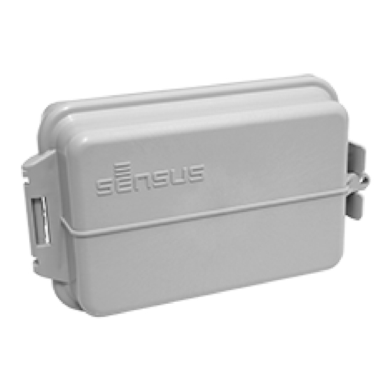
AIG-10043-03
Smart Gateway
Installation Guide
Getting Started
Sensus Provided Components
• Sensus Smart Gateway unit
• Wall Mount Kit: 1 cable gland with single
hole insert (5-10 mm wire), 4 Phillips
head screws, 4 mounting feet
OR
• Pipe/Wall Mount Kit: 1 cable
gland with single hole insert
(5-10mm wire), 4 Phillips head
screws, 2 mounting bars, 4
mounting feet
Fig. 1: Punch cable hole
Installation
1. Using a screwdriver and a hammer,
punch out a hole for the cable
through one of the knock-outs on
the bottom of the enclosure as
shown (Figs. 1&2).
Caution: Take care not to hit or damage the
internal battery.
2. Take the cable gland out of the
provided kit. Install the cable gland
through the hole you just punched
out (Fig. 3) in such a way that the
gasket is on the outside of the
enclosure. Tighten the nut on the
inside but not the cable gland (Fig.
4).
Note: The provided cable gland can
accommodate one (1) 5-10 mm wire. To
accommodate additional wires please order
the optional multi-wire kit from Sensus.
Sensus Optional Components
• Multi-Cable Kit: 1 cable
gland with 2 two hole
inserts (4.5-6mm wire
each) and 1 single hole
insert
Customer Provided
Components
• Transducer with Cable (1)
• Hose clamp (2), ≤.5 in. width - used in
pipe mount
• Appropriate mounting screws - used in
wall mount
Prerequisite(s)
Read all sensor documentation first to
ensure you are familiar with your particular
sensor wiring.
Fig. 2: Cable hole punched out
3. Run your customer provided
transducer cable through the cable
gland and into the center of the
Smart Gateway module (Fig. 5) to
measure the length. Pull back out to
butt the cable sheath approximately
8 inches and strip the wires
approximately .25 inch. Trim any
unnecessary wires.
4. Run the stripped cable through the
cable gland and then tighten the
cable gland to hold the cable in
place. You will want to make sure
that the wire has enough give in it
so the lid will close without bending
or breaking the wire.
5. Using the #0 Phillips screwdriver,
loosen the screws in the terminal
block.
Tools (customer provided)
• Hammer & Wrench
• #2 and #0 Phillips screwdriver
• Wire trimmers
• Large flathead screwdriver (depending
on customer's pipe mount)
Fig. 3: Attach cable gland
Fig. 4: Tighten nut on inside
Fig. 5: Run cable through to measure
Advertisement

Subscribe to Our Youtube Channel
Related Manuals for Sensus AIG-10043-03


Summary of Contents for Sensus AIG-10043-03
- Page 1 Note: The provided cable gland can 5. Using the #0 Phillips screwdriver, accommodate one (1) 5-10 mm wire. To loosen the screws in the terminal accommodate additional wires please order block. the optional multi-wire kit from Sensus. Fig. 5: Run cable through to measure...
- Page 2 AIG-10043-03 Smart Gateway Installation Guide 6. Lace the wires through the fingers the sensor, unit uses on the battery holder before for measurement attaching to the terminal block. 8. Trim and cap any 7. Attach the sensors (Fig. 6) to the unused sensor wires. appropriate pin according to your 9.
- Page 3 Recommendation: Fig. 11: Attach to pipe If installing on a pipe, Sensus recommends that you install the transducer cable into the pipe before wiring it into the Smart Gateway. This will reduce twisting on the transducer cable. Please Note: The FCC etching on the top of the outside enclosure exterior cannot be obstructed from view.
- Page 4 This document, in whole or in part, (“Document”) includes confidential and proprietary information belonging to Sensus USA Inc. and/or one of its subsidiaries or affiliates. Unau- thorized use, reproduction, disclosure, distribution, or dissemination of this Document is strictly prohibited. No party may use, reproduce, disclose, distribute, or disseminate this Document for any purpose without express written authorization from Sensus USA Inc.
Need help?
Do you have a question about the AIG-10043-03 and is the answer not in the manual?
Questions and answers