Rinnai Control-R Installation Manual
Hide thumbs
Also See for Control-R:
- Installation instructions (2 pages) ,
- User manual (41 pages) ,
- Installation manual (20 pages)

Related Manuals for Rinnai Control-R


Summary of Contents for Rinnai Control-R
- Page 1 ENGLISH...
- Page 3 If you contact Rinnai, please have your module’s AYLA ID (located on back of module) and water heater serial number (located on side of water heater) available. Write the numbers...
- Page 4 Module back side contains: • Magnetic backing (for mounting to indoor tankless water heaters) • Keyhole slots (for mounting to wall) • Sticker containing module information including AYLA ID number (required for technical support)
- Page 5 The table below describes possible states for each of the LED color indicators. Color State Condition Yellow Solid Wi-Fi module booting up or updating firmware Blinking Searching for IP address Solid Ready to pair and register Green Solid In accessory pairing mode – searching for wireless on-demand recirculation accessory (push button, motion sensor, etc.)
- Page 6 • Choose a central location where the Wi-Fi signal is strong. Basements and mechanical rooms may have poor wireless signals. • Additional wiring can run up to 300 feet (91 meters) away from the water heater to ensure a strong wireless signal (18-22 gauge wire is required).
- Page 7 You Will Need • Module (supplied) • 2 wall anchors and 2 screws (supplied) • Tools (field-supplied): Phillips head screwdriver, drill with bit set, level and pencil The module’s back panel contains two keyhole slots ❶ that support the module. Mark the location of each slot on the wall with a pencil.
- Page 8 Insert the 2 wall anchors (supplied) into each hole ❸ until they sit flush against the wall. Insert the screws (supplied) into the anchors and ❹ fasten to the wall leaving 1/4 in. exposed. Mount the module by placing the keyhole slots (on ❺...
- Page 9 WARNING To protect yourself from harm, follow the steps below before wiring the module: • Turn off the electrical power supply by unplugging the power cord or by turning off the electricity at the circuit breaker. The temperature controller does not control the electrical power.
- Page 10 ❸ inside the water heater: • For SENSEI™ Tankless Water Heaters, follow steps in section 3(A) (next page). • For all other Rinnai Tankless Water Heaters, see section 3(B). Replace and tighten the four (4) screws on the ❹ water heater cover.
- Page 11 Cut the spade end connectors off the 2 module ❶ wires. Then, strip the insulation off both ends. MODULE Strip Cut end connectors insulation Connect the module cable to the SENSEI™ ❷ controller cable (included in water heater packaging or sold separately) using wire nuts or other approved wire connectors.
- Page 12 Connect the controller cable to the mating terminal at ❸ the bottom right side of the water heater PC Board (through the grommet portal on the bottom right side of the unit). MODULE PC Board Terminal Place the 2 module wires through the bottom ❶...
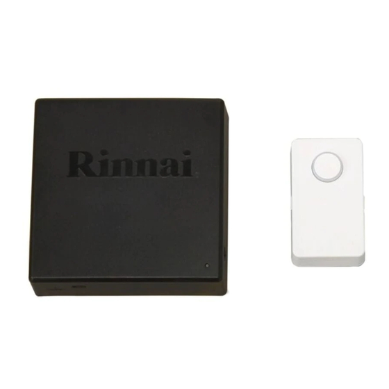
- Page 13 If using the Push Button or Motion Sensor for on-demand recirculation, install and pair them at this time. Push Button Motion Sensor Mounts in a convenient Mounts flush to the wall or in the corner and location, such as a kitchen faucet or operates the recirculation system with...
- Page 14 ❷ Pair the Push Button or Motion Sensor to the module. You Will Need: • Control-R™ Module • Push Button and/or Motion Sensor • Phillips Head Screwdriver (Motion Sensor only) Ensure the module LED has been red for at least...
- Page 15 Press and hold down the Connect button on the module until the LED turns GREEN. Then, release the button (you will need to repeat this process to pair each accessory). You have 5 minutes to pair the Push Button or Motion Sensor with the module before pairing mode times out.
- Page 16 • Use a Phillips Head screwdriver to remove the front cover. • Press and hold down the Connect button on the PCB until the LED double flashes every second. • Release the button. • If paired successfully, the module LED will return to the previous color.
- Page 17 ❸ Install the Push Button or Motion Sensor near the water fixture that will be used frequently, such as a kitchen faucet or bathroom sink. Refer to the instructions in the Push Button or Motion Sensor package for detailed installation steps. Adhere to any wall or counter service using the adhesive backing.
- Page 18 ❶ The module LED will blink yellow until boot-up is complete and will then turn solid RED. ❷ Download the Rinnai app to your smartphone or tablet from the ® ® Apple Store or Google...
- Page 19 ❸...
- Page 20 Local Area Network • Ensure the correct Local Area Wi-Fi signal is Network Wi-Fi password is entered. detected but the • Press Cancel in the Rinnai App Rinnai App cannot and repeat the setup process connect starting from pairing the module...
- Page 21 • For questions about your Internet service, contact your Internet Service Provider (ISP). • For all other questions, contact Rinnai Customer Care at 1-800-621-9419 and have your module’s AYLA ID (located on back of module) and water heater serial number...
- Page 22 Product Rinnai Control-R™ Wi-Fi Module Part Number RWM101 Module 4.8 oz (0.14 kg) Weight Shipping 6 oz (0.17 kg) Carton 3.69 in. x 3.69 in. x 1.18 in. Module (94 mm x 94 mm x 29.97 mm) Dimensions (w, h, d): Shipping 6.125 in.
- Page 23 2006 and later (except the RH180 Hybrid Tank-Tankless Water Heater) Note: The Lime Condition (LC) notification will not appear in the Rinnai App when the module is paired with the following series of Rinnai tankless water heaters manufactured prior to 2009: VA, VB, KA and V53e •...
- Page 24 100000400(02) 08/2018...
Need help?
Do you have a question about the Control-R and is the answer not in the manual?
Questions and answers