Table of Contents
Advertisement
Available languages
Available languages
Quick Links
Advertisement
Chapters
Table of Contents

Related Manuals for ACTEON Equipment SATELEC Implant Center

Summary of Contents for ACTEON Equipment SATELEC Implant Center
- Page 3 English Français Español Deutsch Italiano Nederlands...
-
Page 4: Table Of Contents
NGLISH ONTENTS 1- INTRODUCTION Micro-motor cord and scaler cord maintenance 2- WARNINGS micro-motor maintenance URGE Ultrasound handpiece maintenance 3- DESCRIPTION Tip maintenance Physical description Technical description 7-10 12- MONITORING/PREVENTIVE AND CORRECTIVE MAINTENANCE 4- INSTALLATION/FIRST USE Monitoring Unpacking the device Preventive and corrective Recommendations maintenance Installation... -
Page 5: 1- Introduction
I - INTRODUCTION II - WARNINGS Congratulations! You have just taken possession CAUTION: of your I United States Federal Law restricts the use of ® MPLANT ENTER this device solely to qualified, trained and Designed by SATELEC , the I is a competent dental health practitioners or under ®... - Page 6 Electrical connection: - Make sure that the cords are not in a traffic • Your I must be connected to the path. MPLANT ENTER electric power supply by a certified dental - The device must be stored in its original installation technician.
-
Page 7: Physical Description
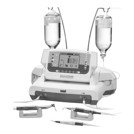
If you have any doubt, contact an approved Located at the back of the unit are: dealer or our customer support department: - 1 power cord socket with ground pin (Figure 2, - www.acteongroup.com (1)), - E-mail: satelec@acteongroup.com. - 1 footswitch connector (Figure 2, (2)), - 1 fan (Figure 2, (3)), - 2 bracket holders (Figure 2, (4)), - 1 power switch (Figure 2, (5)). - Page 8 - Item 12: Irrigation on/off The bracket holders (Fig. 2-4) are used to install - Item 13: Error message zone the brackets. - Item 14: Irrigation flow rate - Item 15: Parameter setting zone The power switch (Fig. 2-5) is used to switch the - Fig.
- Page 9 - Item 2: Select side function IEZOTOME - Item 3: Reverse direction Operation - Item 4: Change program (1 to 4) Intermittent service: 10min ON/5min OFF - Item 5: I-S motor control (ON/OFF or Output characteristics URGE progressive) Voltage: 250volts Min.
-
Page 10: Unpacking The Device
Footswitch: must comply with the applicable standards in Length: 177mm your country. Width: 173mm A grounded power supply socket must be used. Height: 43mm Weight: Max. 700g 4. 3 INSTALLATION LCD screen: Height: 86mm Important: Width: 115mm Do not place the I close to or on MPLANT ENTER... -
Page 11: First Use
VII - ADJUSTMENTS / - Place the N handpiece on the handpiece EWTRON support. SETTINGS / MODES / - Suspend the bottles or bags of physiological saline from the brackets. INTERFACE - Raise the LCD screen. - Adjust the angle of the LCD screen to suit your angle of view. -
Page 12: I-Surge Function
c) Starting/stopping irrigation Select the program for which settings are to be The irrigation is switched on or off by pressing adjusted (Fig. 3-5), then press button or the footswitch button (Fig. 8-1). button ; a cursor appears under CA. When irrigation is selected, the symbol displayed. -
Page 13: Piezotome Function
Note: While the contra-angle is being adjusted, f) Footswitch type selection the maximum permitted speed and torque are When the torque has been adjusted, the cursor is displayed automatically. displayed under the footswitch symbol. Press button to toggle between ON/OFF and d) Speed adjustment progressive. -
Page 14: Newtron Function
The storing of the various settings is confirmed by 7. 7 TOOLBOX an audible signal and by the symbol which blinks on the screen. Important: - The adjusted settings become TOOLBOX Repeat this sequence if necessary in order to effective when the device is restarted. adjust all the programs. -
Page 15: 8- Safety Devices
VIII - SAFETY DEVICES c) Reboot in factory configuration Confirm access to setting by pressing button ; a check mark is displayed next to the selected setting. Confirm the return to the factory configuration The I has a system that detects MPLANT ENTER by pressing button... -
Page 16: 9- Using The Device
IX - USING THE DEVICE - Raise the LCD screen. - Adjust the angle of the LCD screen according to the position of your device and your angle of view. Important: - Make any necessary setting adjustments - Do not disconnect the micro-motor cord or (irrigation flow rate, speed, torque, power, the scaler cord when the device is switched power mode, program, etc.) (refer to chapter... -
Page 17: 10- Shutting Down The Device
X - SHUTTING DOWN THE function IEZOTOME - Connect the P handpiece cord to the IEZOTOME DEVICE right connector of the device (Fig. 1-10). - Screw the selected tip onto the handpiece using a wrench (according to the recommendations of the clinical booklets). -
Page 18: Irrigation Line Maintenance
XI - ROUTINE After each sterilization cycle, remove the items from the autoclave immediately in order MAINTENANCE / to minimize the risks of metal corrosion. STERILIZATION 11. 1 IRRIGATION LINE MAINTENANCE The irrigation lines supplied by SATELEC are disposable and must always be discarded after Important: use. -
Page 19: Micro-Motor Cord And Scaler Cord Maintenance
Regular monitoring of the I unit is The I-S micro-motor must not be cleaned in MPLANT ENTER URGE necessary in order to detect any problem. an ultrasonic bath. It is important to keep the control unit The I-S micro-motor must not be URGE ventilation vents clean in order to avoid disassembled. -
Page 20: Ultrasound Handpiece Maintenance
11. 7 ULTRASONIC HANDPIECE MAINTENANCE b) Cleaning and disinfection: All tips must be cleaned (by brushing, immersion After each use, the handpiece irrigation circuit in an ultrasonic bath, etc.) and disinfected (with must be rinsed with distilled or demineralized an alcohol-impregnated cotton tip, dental water for 20 to 30 seconds. -
Page 21: Preventive And Corrective
12. 2 PREVENTIVE AND CORRECTIVE - Push the fuse drawer back into its housing until MAINTENANCE it clicks to indicate the correct position. - Plug the power cord into the receptacle (Fig. SATELEC recommends inspection or overhaul of 2-1). the I-S micro-motor at least once a year. - Page 22 Fault detected Possible causes Solutions Adjust the speed in accordance with good Incorrect speed adjustment. dental practice. Speed fault - Change the contra-angle. Wrong contra-angle. - Return to SATELEC after-sales. Replace the bag or bottle of irrigation Irrigation solution bag or bottle empty. solution.
-
Page 23: 13- Electromagnetic Compatibility
XIII - ELECTROMAGNETIC COMPATIBILITY Important: The power cord, the micro-motor cord, the ultrasonic handpiece cords and the multifunction footswitch cord must be kept away from each other. The I requires special precautions to be taken with regard to electromagnetic MPLANT ENTER compatibility. -
Page 24: Electromagnetic Immunity
13. 2 ELECTROMAGNETIC IMMUNITY The I is intended for use in the electromagnetic environment specified in the table below. MPLANT ENTER The user and/or installer must ensure that the I is used in such an electromagnetic MPLANT ENTER environment. Immunity test IEC 60601 test level Compliance level Electromagnetic environment - guidance... -
Page 25: Recommended Separation Distances
Note 1: At 80 MHz and 800 MHz, the higher frequency range applies. Note 2: These specifications may not be applicable in all situations. Electromagnetic propagation is affected by absorption and reflection from structures, objects and persons. (a): The electromagnetic field strengths of fixed radiofrequency emitters, such as base stations for mobile telephones (cellular/cordless), mobile radios, amateur radio, AM/FM radio broadcasts and TV broadcasts cannot be determined exactly by theory. -
Page 26: Cable Lengths
10. 5 CABLE LENGTHS Cables and accessories Maximum length Complies with: RF emission, CISPR 1 - Class B/Group 1 Harmonic current emission: IEC61000-3-2 Voltage fluctuation: IEC61000-3-3 Handpiece cords Immunity to electrostatic discharge: IEC61000-4-2 Immunity to electrical fast transients/bursts: IEC61000-4-4 Footswitch cord Less than 3m Immunity to surges: IEC61000-4-5 Immunity to voltage dips, short interruptions and voltage variations:... -
Page 27: 16- Regulations
XVI - REGULATIONS This medical device is classified as class IIa according to European directive 93/42/EEC. This equipment is manufactured in compliance with the current IEC 60601-1 standard. This equipment has been designed and developed according to an ISO 13485-certified quality assurance system. - Page 28 RANÇAIS OMMAIRE 1 INTRODUCTION Entretien des cordons micro-moteur et détartreur 2 AVERTISSEMENTS 29-31 Entretien du micro-moteur I-S URGE Entretien des pièces à main ultrasons 44 3 DESCRIPTION Entretien des inserts Description physique Description technique 31-34 12 SURVELLANCE/MAINTENANCE Surveillance 4 INSTALLATION / MISE EN SERVICE Maintenance Déballage de l'appareil Remplacement des fusibles...
-
Page 29: Introduction
I - INTRODUCTION II - AVERTISSEMENTS Vous venez de prendre possession de votre ATTENTION : appareil I , nous vous en félicitons. La loi fédérale (Federal Law) des Etats-Unis ® MPLANT ENTER restreint l'utilisation appareil Créé par la société SATELEC uniquement aux professionnels de santé... - Page 30 Raccordement électrique : - Ne pas disposer l'appareil près d'une source de - Faire exécuter les raccordements de votre chaleur. appareil au réseau électrique par un technicien - Veiller à ce que les cordons n'entravent pas la installateur dentaire agréé. libre circulation des personnes.
-
Page 31: Description
votre appareil dangereux pour vous et vos A l'arrière du boîtier se trouvent différents patients. éléments : - 1 embase secteur avec broche de terre (Fig. 2, En cas de doute, contacter un revendeur agréé ou rep. 1). le service clients SATELEC : - 1 connecteur pédale (Fig. - Page 32 - Rep. 13 : Zone de message d'erreur. permettent la mise en place des potences. - Rep. 14 : Débit d'irrigation. - Rep. 15 : Zone de réglage des paramètres. L'interrupteur secteur (Fig. 2, rep. 5) permet de - Fig. 3, Rep. 25 : Côté sélectionné. mettre l'appareil sous tension ou hors tension.
- Page 33 - Rep. 4 : Changement de programme (de 1 à 4). Fonction P IEZOTOME - Rep. 5 : Activation du moteur I-S (type Fonctionnement : URGE ON/OFF ou progressif). Service intermittent : 10 mn ON/ 5 mn OFF Caractéristiques de sortie : Mode P Tension : 250 Volts IEZOTOME...
-
Page 34: Installation / Mise En Service
Pédale : être conforme aux normes en vigueur de votre Longueur : 177 mm pays. Largeur : 173 mm L'utilisation d’une prise secteur avec broche de Hauteur : 43 mm terre est obligatoire. Poids : 700 g max Ecran LCD : 4. -
Page 35: Première Mise En Service
VII - REGLAGES / - Poser la pièce à main N sur le support de EWTRON pièce à main. PARAMETRES / MODES - Suspendre les flacons ou les poches de sérum physiologique aux potences. / INTERFACE - Relever l'écran LCD. - Régler l'inclinaison de l'écran LCD selon l'emplacement de votre appareil et de votre angle de vision. -
Page 36: Fonction I-Surge
c) Activation / désactivation de l'irrigation Le réglage des paramètres se fait selon l'ordre L'activation ou la désactivation de l'irrigation se suivant : fait par l'intermédiaire d'une impulsion sur le 1- Choix du contre-angle. bouton ou sur la touche de la pédale (Fig. 8, 2- Réglage de la vitesse. -
Page 37: Fonction Piezotome
Valider la valeur finale en appuyant sur le bouton Régler la valeur du premier chiffre en utilisant les boutons (Fig. 3, rep. 7 et 9). Nota : Durant le réglage du contre-angle, la Appuyer sur le bouton . Le curseur se place vitesse maximale et le couple maximal autorisés ainsi sous le prochain chiffre. -
Page 38: Fonction Newtron
Sélectionner le programme devant être utilisé Valider le réglage du mode en appuyant sur le (Fig. 3, rep. 5), le programme bouton sélectionné apparaît sur l'écran LCD. La mémorisation des différents paramètres est Pour valider le choix du programme, appuyer sur confirmée par un signal sonore et par le symbole le bouton qui clignote à... -
Page 39: Securites
b) Réglage de la temporisation à l'extinction de Mode N EWTRON la lumière Programme Fonction Puissance Irrigation Valider l'entrée dans le paramètre en appuyant sur le bouton Vert Soft P = 5 15 ml/min Le curseur apparaît sous la valeur de la durée de Jaune Medium P = 5... -
Page 40: Utilisation De L'appareil
IX - UTILISATION DE - Baisser les capots. - Relier les perforateurs des lignes d'irrigation aux L'APPAREIL flacons ou aux poches de sérum physiologique. - Relever l'écran LCD. - Régler l'inclinaison de l'écran LCD selon l'emplacement de votre appareil et de votre Important : angle de vision. -
Page 41: Arret De L'appareil
le bouton de purge du clavier de commande cordon détartreur. (Fig. 3, rep. 1). - Amorcer le circuit d'irrigation en appuyant sur - A l'arrivée de la solution d'irrigation en bout de le bouton de purge de la pédale multifonctions. contre-angle, relâcher la pédale. -
Page 42: Entretien Des Lignes D'irrigation
XI - ENTRETIEN ET Avant toute stérilisation, vérifier la propreté de votre autoclave ainsi que la qualité de l'eau STERILISATION utilisée. Après chaque cycle de stérilisation, sortir immédiatement les éléments de l'autoclave afin de réduire les risques de corrosion des Important : parties métalliques. -
Page 43: Entretien Des Cordons Micro-Moteur
désinfection, lingettes désinfectantes de cabinet Le micro-moteur I-S ne doit pas être URGE dentaire, type S ™ L ) de façon immergé ni désinfecté avec des agents EPTOL INGETTES systématique après chaque intervention. contenant de l'acétone, du chlore ou de l'eau de javel. -
Page 44: Entretien Des Pièces À Main Ultrasons
11. 7 ENTRETIEN PIÈCES À MAIN b) Nettoyage et désinfection ULTRASONS Tout insert doit être nettoyé (par brossage, immersion dans une cuve à ultrasons…) et Après chaque utilisation, le circuit d'irrigation désinfecté avant la stérilisation (avec un coton des pièces à main doit être rincé à l'eau distillée imbibé... -
Page 45: Maintenance
12. 2 MAINTENANCE de même type et de même valeur. - Replacer le tiroir à fusibles dans son logement Contrôle/révision du micro-moteur I-S en le poussant jusqu'à entendre un déclic qui URGE SATELEC recommande de faire contrôler ou confirme un positionnement correct. réviser le micro-moteur I-S au moins une fois - Brancher le cordon secteur à... - Page 46 Anomalies Constatées Causes Possibles Solutions Régler la vitesse conformément à l'état de Mauvais réglage de la vitesse. l'art dentaire. Défaut de vitesse - Changer de contre-angle. Contre angle inadapté. - Retour au S.A.V. SATELEC. Poche ou flacon de solution d'irrigation Remplacer la poche ou le flacon de vide.
-
Page 47: Compatibilite Electromagnetique
XIII - COMPATIBILITE ELECTROMAGNETIQUE Important : Le cordon secteur, le cordon micro-moteur, les cordons de pièce à mains ultrasons et le cordon de la pédale multifonctions doivent être éloignés les uns des autres. nécessite de prendre des précautions particulières en ce qui concerne la compatibilité MPLANT ENTER électromagnétique. -
Page 48: Immunité Électromagnétique
13. 2 IMMUNITÉ ÉLECTROMAGNÉTIQUE est destiné à une utilisation dans l'environnement électromagnétique du tableau ci- MPLANT ENTER dessous. L'utilisateur et/ou l'installateur devra s'assurer que son appareil est utilisé dans un tel environnement électromagnétique. Test d'immunité Niveau de test selon IEC60601 Niveau de conformité... -
Page 49: Distances De Séparation Recommandées
Remarque 1 : A 80 MHz et 800 MHz, la gamme de fréquence la plus élevée s'applique. Remarque 2 : Ces spécifications peuvent ne pas s'appliquer dans toutes les situations. La propagation électromagnétique est affectée par l'absorption et la réflexion des structures, des objets et des personnes. -
Page 50: Longueur Des Câbles
13. 5 LONGUEUR DES CÂBLES Câbles et accessoires Longueur Maximale En conformité avec : Emission RF, CISPR 1 - Classe B / Groupe 1 Emission de courants harmoniques : IEC61000-3-2 Cordon de Pièce à Main Fluctuation de tension : IEC61000-3-3 Immunité... -
Page 51: Reglementation
XVI - RÉGLEMENTATION Ce dispositif médical est classé IIa selon la directive européenne CEE/93/42. Ce matériel est fabriqué en conformité avec la norme en vigueur suivante IEC60601-1. Ce matériel a été conçu et fabriqué selon un système d'assurance qualité certifié EN ISO 13485. - Page 52 SPAÑOL Í NDICE 1 INTRODUCCIÓN Mantenimiento del equipo 66-67 Mantenimiento del cable 2 ADVERTENCIA 53-55 micromotor y detartrador Mantenimiento del micromotor 3 DESCRIPCIÓN URGE Descripción física Mantenimiento de las piezas de mano 68 Descripción técnica 55-58 Mantenimiento de los insertos 4 INSTALACIÓN / PUESTA EN MARCHA 12 VIGILANCIA / MANTENIMIENTO Desembalaje del equipo...
-
Page 53: Introducción
I - INTRODUCCIÓN II - ADVERTENCIA Acaba de adquirir su equipo I ATENCIÓN: ® MPLANT ENTER ¡enhorabuena! La ley federal (Federal Law) de los Estados Unidos limita el uso de este equipo sólo a los Creado por la sociedad SATELEC , el I profesionales diplomados de la salud dental, ®... - Page 54 Conexión eléctrica: - No colocar el equipo cerca de una fuente de - Mandar ejecutar las conexiones de su aparato a calor. la red eléctrica por un técnico instalador dental - Asegurarse de que los cables no dificulten el autorizado. paso de las personas.
-
Page 55: Descripción
En caso de duda, póngase en contacto con un En la parte posterior de la caja se encuentran distribuidor autorizado o el servicio de atención diferentes elementos: al Cliente: - 1 conector fijo de red con toma de tierra - www.acteongroup.com (Fig. - Page 56 - Rep. 12 : Irrigación activada o desactivada. los soportes para bolsas de irrigación. - Rep. 13 : Zona de mensaje de error. - Rep. 14 : Caudal de irrigación. El interruptor de la red eléctrica (Fig. 2, rep. 5) - Rep.
- Page 57 - Rep. 4 : Cambiar el programa (de 1 a 4). Función P IEZOTOME - Rep. 5 : Activar el motor I-S (tipo ON/OFF o Funcionamiento: URGE progresivo). Servicio intermitente : 10 min ON/ 5 min OFF Características de salida: Modo P Tensión: 250 Voltios IEZOTOME...
-
Page 58: Instalación / Puesta En Marcha
Pedal: La conexión eléctrica del I debe MPLANT ENTER Longitud: 177 mm cumplir con las normas vigentes en su país. Anchura: 173 mm Es obligatorio el uso de una toma eléctrica con Altura: 43 mm tierra. Peso: 700 gramos máx Pantalla LCD: 4. -
Page 59: Primera Puesta En Marcha
VII - AJUSTES / - Colgar los frascos o las bolsas de suero fisiológico en los soportes. PARÁMETROS / MODOS - Elevar la pantalla LCD. - Ajustar la inclinación de la pantalla LCD según / INTERFAZ el emplazamiento del equipo y el ángulo de visión. -
Page 60: Función I-Surge
c) Activar / desactivar la irrigación El ajuste de los parámetros se realiza en el orden La activación o desactivación del caudal de siguiente: irrigación se realiza pulsando el botón o la 1- Selección del contraángulo. tecla del pedal (Fig. 8, rep. 1). 2- Ajuste de la velocidad. -
Page 61: Función Piezotome
Nota : Durante el ajuste del contraángulo, la Ajustar el valor de la primera cifra utilizando los velocidad máxima y el par máximo autorizados botones (Fig. 3, rep. 7 y 9). aparecen automáticamente. Pulsar el botón . El cursor se sitúa así en la próxima cifra. -
Page 62: Función Newtron
Seleccionar el programa que debe utilizarse Validar el ajuste del modo pulsando el botón (Fig. 3, rep. 5); el programa Una señal sonora y el símbolo que parpadea en seleccionado aparece en la pantalla LCD. la pantalla confirman la memorización de los Para validar la selección del programa, pulsar el diferentes parámetros. -
Page 63: Seguridad
b) Ajuste de la temporización en la extinción Mode N EWTRON de la luz Programa Función Potencia Irrigación Validar la entrada en el parámetro pulsando el botón Verde Soft P = 5 15 ml/min El cursor aparece en el valor de la duración de Amarillo Medium P = 5... -
Page 64: Uso Del Equipo
IX - USO DEL APARATO irrigación en los frascos o las bolsas de suero fisiológico. - Elevar la pantalla LCD. - Ajustar la inclinación de la pantalla LCD según Importante: el emplazamiento del equipo y el ángulo de - No desconectar el cable micromotor o el cable visión. -
Page 65: Paro Del Equipo
- Cuando la solución de irrigación llegue al cabo - Cebar el circuito de irrigación pulsando el botón del contraángulo soltar el pedal. de purgar del pedal multifunción. - Utilizar el I de acuerdo con las - A la llegada de la solución de irrigación al cabo MPLANT ENTER normas del arte dental. -
Page 66: Mantenimiento / Esterilización
XI - MANTENIMIENTO / Después de cada ciclo de esterilización, retirar inmediatamente los elementos de la autoclave ESTERILIZACIÓN para reducir los riesgos de corrosión de las partes metálicas. 11. 1 MANTENIMIENTO DE LAS LÍNEAS DE Importante: IRRIGACIÓN No se entrega estéril ningún accesorio, salvo las líneas de irrigación. -
Page 67: Mantenimiento Del Cable
desinfectantes de la consulta dental de tipo No debe desinfectarse el micromotor I-S URGE ™ L ) de forma sistemática después con agentes que contengan acetona, cloro o EPTOL INGETTES de cada intervención. lejía. Es necesario vigilar con regularidad la caja del No debe limpiarse el micromotor I-S en una URGE... -
Page 68: Mantenimiento De Las Piezas De Mano
11. 7 MANTENIMIENTO DE LAS PIEZAS DE MANO b) Limpieza y desinfección Todo inserto debe limpiarse (cepillándolo, Después de cada uso, debe aclararse el circuito inmergiéndolo en una cuba de ultrasonidos…) y de irrigación de las piezas de mano con agua desinfectarse antes de la esterilización (con un destilada o desmineralizada durante 20 a 30 algodón empapado en alcohol, toallitas de... -
Page 69: Mantenimiento
12. 2 MANTENIMIENTO - Volver a colocar el compartimiento fusible en su receptáculo, empujándolo hasta escuchar un Control / revisión del micromotor I-S chasquido confirma correcto URGE SATELEC recomienda hacer controlar o revisar el posicionamiento. micromotor I-S al menos una vez al año. - Enchufar el cable de red en su base (Fig. - Page 70 Anomalías Detectadas Posibles Causas Soluciones Ajustar la velocidad de acuerdo con las Ajuste incorrecto de la velocidad. normas del arte dental. Fallo de velocidad - Cambiar de contraángulo. Contraángulo no adaptado. - Remisión al S.P.V. SATELEC. Bolsa o frasco de solución de irrigación Remplazar la bolsa o frasco de solución de vacía.
-
Page 71: Compatibilidad Electromagnética
XIII - COMPATIBILIDAD ELECTROMAGNÉTICA Importante: El cable de red, el cable micromotor, los cables de pieza de mano ultrasonidos y el cable del pedal multifunción deben estar alejados los unos de los otros. El I necesita tomar en consideración precauciones particulares en cuanto a MPLANT ENTER compatibilidad electromagnética se refiere. -
Page 72: Inmunidad Electromagnética
13. 2 INMUNIDAD ELECTROMAGNÉTICA El I esta destinado a ser utilizado en el entorno electromagnético del cuadro siguiente. MPLANT ENTER El usuario y /o el instalador deberán asegurarse de que el equipo se utiliza en el entorno electromagnético descrito a continuación. Prueba de inmunidad Nivel de prueba según IEC60601 Nivel de conformidad Entorno electromagnético - observaciones... -
Page 73: Distancias De Separación Recomendadas
Observación 1: A 80 MHz y 800 MHz, se aplica la gama de frecuencia más elevada. Observación 2: Estas especificaciones puede que no se apliquen en todas las situaciones. La propagación electromagnética está afectada por la absorción y la reflexión de las estructuras, los objetos y las personas. -
Page 74: Longitud De Los Cables
13. 5 LONGITUD DE LOS CABLES Cables y accesorios Longitud máxima En conformidad con: Emisión RF, CISPR 1 - Clase B / Grupo 1 Emisión de corrientes armónicas - IEC61000-3-2 Cables de pieza de Fluctuación de tensión - IEC61000-3-3 mano Inmunidad a las descargas electroestáticas - IEC61000-4-2 Inmunidad a los transitorios eléctricos rápidos en salva - IEC61000-4-4 Cable de pedal de... -
Page 75: Reglamentación
XVI - REGLAMENTACIÓN Este dispositivo médico está clasificado IIa según la directiva europea CEE/93/42. Este material está fabricado de acuerdo con la norma vigente siguiente IEC60601-1. Este material se ha desarrollado y diseñado según un sistema de garantía de calidad certificado ISO 13485. - Page 76 EUTSCH NHALT 1 EINLEITUNG Wartung des Gerätes 90-91 Wartung der Kabel für 2 BESONDERE HINWEISE - Mikromotor und Zahnsteinentferner WARNUNGEN 77-79 Wartung des I-S -Mikromotors URGE Wartung der Ultraschall-Handstücke 92 3 BESCHREIBUNG Wartung der Spitzen Beschreibung des Gerätes Technische Beschreibung 79-82 12 ÜBERWACHUNG / WARTUNG Regelmäßige Überprüfung...
-
Page 77: Einleitung
I - EINLEITUNG II - BESONDERE HINWEISE - WARNUNGEN Sie sind soeben Besitzer eines I ® MPLANT ENTER geworden, herzlichen Glückwunsch! ACHTUNG: Die Firma SATELEC hat I als ein Durch das Bundesgesetz (Federal Law) der ® MPLANT ENTER Multifunktionsgerät entwickelt. Es ermöglicht die Vereinigten Staaten von Amerika wird die Ausführung von: Benutzung dieses Gerätes ausschließlich auf... - Page 78 Elektroanschluss: - Das Gerät nicht um mehr als 5 Grad neigen. - Der Anschluss Ihres Gerätes an das elektrische - Das Gerät nicht in die Nähe einer Wärmequelle Leitungsnetz muss von einem autorisierten stellen. Installateur für zahnmedizinische Geräte - Auf Kabel und Schläuche am Fußboden achten, ausgeführt werden.
-
Page 79: Beschreibung
irgendeinen Reparaturbetrieb, durch dessen - 1 Fußschaltersteckbuchse (Abb. 2, Nr. 2) Intervention das Gerät für Sie und für Ihre - 1 Ventilator (Abb. 2, Nr. 3) Patienten gefährlich werden könnte. - 2 Träger für die Flaschenhalter (Abb. 2, Nr. 4) Im Zweifelsfall und bei Fragen wenden Sie sich - 1 Netzschalter (Abb. - Page 80 Die Betriebsart I-S Pumpenrad werden Pumpendeckel URGE Lage der Leuchtanzeigen und Informationen hochgeklappt und das Pumpenrad horizontal in (Abb. 5, Nr. 16 bis 19). die hierfür bestimmten Fächer eingesetzt. - Nr. 16: Drehrichtung. - Nr. 17: Typ des Steuerpedals. d) Vorderseite - Nr.
- Page 81 Die Betriebsart N Die Funktion N EWTRON EWTRON Definition der Tasten des Fußschalters (Abb. 8, Betrieb: Nr. 1 bis 5). Intermittierender Betrieb: 10 Minuten Betrieb / - Nr. 1: Spülvorgang einschalten / ausschalten. 5 Minuten Pause - Nr. 2: Seitenwahl. Ausgangsleistung: - Nr.
-
Page 82: Installation / Inbetriebnahme
LCD-Bildschirm: 4. 3 INSTALLATION Höhe: 86 mm Breite: 115 mm Wichtig: Mikromotor-Kabel: 2000 mm Achten Sie darauf, dass I nicht in MPLANT ENTER Zahnsteinentferner-Handstück-Kabel: 2000 mm der Nähe eines anderen Gerätes oder auf Mikromotor I-S einem anderen Gerät aufgestellt wird. URGE Länge: 99 mm Das Netzkabel und das Fußschalterkabel dürfen... -
Page 83: Erste Inbetriebnahme
VII - EINSTELLUNGEN / - Hängen Sie die Flaschen oder Beutel mit physiologischer Kochsalzlösung PARAMETER / Flaschenhalter. - Klappen Sie den LCD-Bildschirm hoch. BETRIEBSARTEN / - Stellen Sie die Neigung des LCD-Bildschirms entsprechend dem Standort Ihres Gerätes und BENUTZERSCHNITTSTELLE Ihrem Sichtwinkel ein. 4. - Page 84 c) Einschalten / Ausschalten des Spülvorgangs Die Parameter sind in der folgenden Reihenfolge Der Spülvorgang wird durch Drücken der Taste einzustellen: oder der entsprechenden Fußschaltertaste ein- 1- Wahl des Winkelstücks oder ausgeschaltet (Abb. 8, Nr. 1). 2- Einstellen der Geschwindigkeit Wenn der Spülvorgang aktiviert ist, leuchtet das 3- Einstellen des Drehmoments Symbol...
-
Page 85: Die Funktion Piezotome
Bestätigen Sie den endgültigen Wert durch e) Einstellen des Drehmoments Drücken der Taste Drücken Sie auf die Taste . Dann positioniert Hinweis: Während Einstellens sich der Cursor unter der ersten Zahl. Winkelstücks werden die zulässige maximale Stellen Sie den Wert der ersten Zahl mit den Geschwindigkeit und das zulässige maximale Tasten oder... -
Page 86: Die Funktion Newtron
Wählen Sie das Programm oder aus, Ein Signalton und die Anzeige des Symbols , das das benutzt werden soll (Abb. 3, Nr. 5). Das auf dem Bildschirm aufblinkt, zeigen an, dass die gewählte Programme wird dann auf dem LCD- verschiedenen Parameter abgespeichert wurden. Bildschirm angezeigt. -
Page 87: Schutzhinweise
Dann erscheint der Cursor unter dem Wert der Die N -Betriebsart: EWTRON Abschaltzeit. Durchfluss- Programm Funktion Leistungsstufe Stellen Sie den Wert der Abschaltzeit von 0 bis 10 menge ein, indem Sie die Tasten drücken (Abb. Grün Soft P = 5 15 ml/min 3, Nr. -
Page 88: Die Benutzung Des Gerätes
IX - DIE BENUTZUNG DES horizontal in die hierfür bestimmten Fächer ein. - Schließen Sie die Deckel wieder. GERÄTES - Stecken Sie die Lanzette der Steril-Spüllinien in die Flaschen oder Beutel mit physiologischer Kochsalzlösung. - Klappen Sie den LCD-Bildschirm hoch. Wichtig: - Stellen Sie die Neigung des LCD-Bildschirms - Die Stecker des Mikromotor-Kabels und des... -
Page 89: Abschalten Des Gerätes
- Den Spülkreislauf durch Drücken der Taste Entleeren - Das Ende der Steril-Spüllinie mit dem Kabel des auf dem Tastaturfeld betätigen (Abb. 3, Nr. 1). Zahnsteinentferners verbinden. - Wenn die Spüllösung am Ende des Winkelstücks - Den Spülkreislauf durch Drücken der Taste Entleeren angekommen ist, der Fußschalter loslassen. -
Page 90: Wartung / Sterilisierung
XI - WARTUNG / 11. 1 WARTUNG DER STERIL-SPÜLLINIEN STERILISIERUNG Die Steril-Spüllinien von SATELEC sind für den Einmalgebrauch bestimmt müssen systematisch nach jeder Verwendung entsorgt werden. Durch die erneute Verwendung einer Wichtig: Steril-Spüllinie können Ihre Patienten Außer Steril-Spüllinien wird kein kontaminiert werden. -
Page 91: Urge -Mikromotors
des I ist notwendig, um eventuelle Natronbleichlauge (Eau de Javel) enthalten. MPLANT ENTER Probleme festzustellen. Der I-S -Mikromotor darf nicht in einem URGE Überwachung Sauberkeit Ultraschall-Becken gereinigt werden. Lüftungsöffnungen der Steuereinheit ist wichtig, -Mikromotor darf nicht URGE um eine anormale Erhitzung zu vermeiden. auseinandergenommen werden. -
Page 92: Wartung Der Spitzen
11. 7 WARTUNG DER ULTRASCHALL- b) Reinigung und Desinfektion HANDSTÜCKE Vor der Sterilisierung (mit einem mit Alkohol getränkten Wattestäbchen, üblichen Nach jeder Benutzung muss der Spülkreislauf der Reinigungstüchern für Zahnarztpraxen des Typs Handstücke mit destilliertem oder vollentsalztem ™…) muss eine Spitze immer gereinigt EPTOL Wasser 20 bis 30 Sekunden lang durchgespült werden (durch Bürsten, Eintauchen in ein... -
Page 93: Wartung
12. 2 WARTUNG des gleichen Typs und der gleichen Stärke ersetzen. Kontrolle / Überholung des I-S -Mikromotors: - Das Sicherungsfach wieder einsetzen und URGE SATELEC empfiehlt, Kontrolle oder zuschieben, bis ein Klicken hörbar ist, das die Überholung des I-S -Mikromotors mindestens korrekte Position bestätigt. - Page 94 Störung Mögliche Ursachen Lösung Die Geschwindigkeit gemäß den Anforderungen Geschwindigkeit falsch eingestellt. der Zahnmedizin einstellen. Mangelhafte - Das Winkelstück auswechseln. Geschwindigkeit Winkelstück ungeeignet. - Das Gerät dem SATELEC-Kundendienst übergeben. Der Beutel oder die Flasche mit Den Beutel oder die Flasche mit Spüllösung Spüllösung ist leer.
-
Page 95: Elektromagnetische Kompatibilität
XIII - ELEKTROMAGNETISCHE KOMPATIBILITÄT Wichtig: Das Netzkabel, das Mikromotorkabel, die Kabel des Ultraschall-Handstücks und das Kabel des Multifunktions-Fußschalters müssen voneinander getrennt verlaufen. Für I müssen besondere Vorkehrungen hinsichtlich der elektromagnetischen MPLANT ENTER Kompatibilität getroffen werden. Das Gerät muss gemäß den Anweisungen in Kapitel 4 installiert und in Betrieb genommen werden. Bei bestimmten Arten von Mobilfunkgeräten wie Handys kann es zu Interferenzen mit I MPLANT ENTER... -
Page 96: Elektromagnetischer Schutz
13. 2 ELEKTROMAGNETISCHER SCHUTZ ist für eine Verwendung in elektromagnetischer Umgebung gemäß nachfolgender Tabelle MPLANT ENTER bestimmt. Der Benutzer und / oder der Installateur muss sich vergewissern, dass I in einer solchen MPLANT ENTER elektromagnetischen Umgebung benutzt wird. Schutztest Testniveau gemäß IEC60601 Konformitätsniveau Elektromagnetische Umgebung - Hinweise Die Böden müssen aus Holz, Beton, Zement oder... -
Page 97: Empfohlene Trennabstände
Hinweis 1: Bei 80 MHz und 800 MHz gilt der höhere Frequenzbereich. Hinweis 2: Es ist möglich, dass diese Spezifikationen nicht für alle Situationen gelten. Die elektromagnetische Ausbreitung wird durch die Absorption und die Reflexion der Strukturen, Gegenstände und Personen beeinflusst. (a) : Die Intensitäten der elektromagnetischen Felder von festen HF-Sendern wie Basisstationen für tragbare Telefone (Handys / drahtlose), Mobilfunkgeräte, Amateurfunkgeräte, Radiosender AM/FM und TV-Sender können in der Theorie nicht exakt bestimmt werden. -
Page 98: Länge Der Kabel
13. 5 LÄNGE DER KABEL Kabel und Zubehör Maximale Länge Konform zu HF-Emission, CISPR 1 - Klasse B / Gruppe 1 Begrenzung der Störaussendungen Oberschwingungen: IEC61000-3-2 Begrenzung der Störaussendungen Spannungsschwankungen: IEC61000-3-3 Handstückkabel Schutz vor elektrostatischen Entladungen: IEC61000-4-2 Schutz vor schnellen elektrischen Transienten in Salve: IEC61000-4-4 Unter 3 m Schutz vor Stoßspannungen: IEC61000-4-5 Fußschalterkabel... -
Page 99: Vorschriften
XVI - VORSCHRIFTEN Diese medizinische Vorrichtung ist eingestuft in die Klasse IIa gemäß der europäischen Richtlinie CEE/93/42. Dieses Gerät ist hergestellt gemäß der folgenden Norm: IEC60601-1. Dieses Gerät wurde entwickelt und konzipiert unter einem Qualitätssicherungssystem, das gemäß ISO 13485 zertifiziert ist. XVII - SYMBOLE Wechselstrom Gerät des Typs Niederfrequenz (BF) - Page 100 TALIANO NDICE 1 INTRODUZIONE Manutenzione dell'apparecchio 114-115 Manutenzione del cordone 2 AVVERTENZE 101-103 micromotore e ablatore di tartaro Manutenzione del micromotore 3 DESCRIZIONE URGE Descrizione fisica Manutenzione dei manipoli a Descrizione tecnica 103-106 ultrasuoni Manutenzione delle punte 4 INSTALLAZIONE / MESSA IN FUNZIONE Disimballaggio dell'apparecchio 12 CONTROLLO / MANUTENZIONE Raccomandazioni...
-
Page 101: Introduzione
I - INTRODUZIONE II - AVVERTENZE Congratulazioni per aver scelto un apparecchio ATTENZIONE: La legge federale (Federal Law) degli Stati Uniti ® MPLANT ENTER limita l'uso di questo apparecchio unicamente Creato dalla società SATELEC , l'I è ai professionisti del settore dentale, laureati ®... - Page 102 Collegamento elettrico: - Non posizionare l'apparecchio nei pressi di una - Far eseguire il collegamento del vostro fonte di calore. apparecchio alla rete di alimentazione elettrica - Fare attenzione che i cordoni non ostacolino la installatore apparecchiature libera circolazione delle persone. odontoiatriche autorizzato.
-
Page 103: Descrizione
In caso di dubbio, contattare un rivenditore - 1 ventilatore (Fig. 2, rif. 3). autorizzato o il servizio clienti: - 2 supporti di sostegno (Fig. 2, rif. 4). - www.acteongroup.com - 1 interruttore di alimentazione (Fig. 2, rif. 5). - Email : satelec@acteongroup.com. 3. - Page 104 - Rif. 15 : Zona di regolazione dei parametri. L'interruttore di alimentazione (Fig. 2, rif. 5) - Fig. 3, rif. 25 : Lato selezionato. permette di alimentare o di scollegare l'apparecchio. Modalità I-S URGE Posizionamento delle visualizzazioni c) Lati dell'unità di comando informazioni luminose (Fig.
- Page 105 Modalità P Frequenza modulazione: 60Hz / 30Hz / 10Hz a IEZOTOME Definizione dei tasti del pedale (Figura 8, seconda della modalità riferimenti da 1 a 5). Erogazione liquido d'irrigazione: da 5 a 80 ml/min - Rif. 1: Attivazione / disattivazione dell'irrigazione. (valore nominale).
-
Page 106: Installazione / Messa In Funzione
Schermo LCD: L'utilizzo di una presa di alimentazione con la sua Altezza: 86 mm spina di terra è obbligatorio. Larghezza: 115 mm Cordone micromotore: 2000 mm 4. 3 INSTALLAZIONE Cordone manipolo ablatore di tartaro: 2000 mm Micromotore I-S Importante: URGE lunghezza: 99 mm Fare attenzione a non installare l'I MPLANT... -
Page 107: Prima Messa In Funzione
VII - REGOLAZIONI/ - Posare il manipolo N sull'apposito EWTRON supporto. PARAMETRI/MODALITÀ - Appendere i flaconi o le sacche di soluzione fisiologica ai sostegni. /INTERFACCIA - Sollevare lo schermo LCD. - Regolare l'inclinazione dello schermo LCD in base alla posizione del vostro apparecchio e del vostro angolo di visione. - Page 108 c) Attivazione / disattivazione dell'irrigazione La regolazione dei parametri si fa in base al L'attivazione o la disattivazione dell'irrigazione si seguente ordine: esegue premendo il pulsante o il tasto del 1- Scelta del contrangolo. pedale (Fig. 8, rif. 1). 2- Regolazione della velocità. Quando viene selezionata l'irrigazione, si accende 3- Regolazione della coppia.
-
Page 109: Funzione Piezotome
Nota: Durante la regolazione del contrangolo, la Premere il pulsante . Il cursore si posiziona velocità e la coppia massime autorizzate sotto la cifra successiva. appaiono automaticamente. Ripetere questa sequenza cifra per cifra. d) Regolazione della velocità Convalidare il valore della coppia premendo il Dopo aver scelto o regolato il contrangolo, il pulsante cursore appare sotto rpm (giri al minuto) (Fig. -
Page 110: Funzione Newtron
Selezionare il programma da utilizzare Convalidare la regolazione della modalità (Fig. 3, rif. 5); il programma selezionato premendo il pulsante apparirà, sullo schermo LCD. La memorizzazione dei vari parametri è Per convalidare la scelta del programma, confermata da un segnale acustico e dal simbolo premere il pulsante che lampeggia sullo schermo. -
Page 111: Sicurezza
b) Regolazione della temporizzazione di Modalità N EWTRON spegnimento della luce Programma Funzione Potenza Irrigazione Convalidare l'ingresso nel parametro premendo il pulsante . Il cursore appare sotto il valore Verde Soft P = 5 15 ml/min della durata di temporizzazione. Giallo Medium P = 5... -
Page 112: Utilizzo Dell'apparecchio
IX - UTILIZZO flaconi o nelle sacche di soluzione fisiologica. - Sollevare lo schermo LCD. DELL'APPARECCHIO - Regolare l'inclinazione dello schermo LCD a seconda della posizione del vostro apparecchio e del vostro angolo di visione. - Effettuare le regolazioni dei parametri voluti Importante: (erogazione liquido d'irrigazione, velocità, coppia, - Non staccare il cordone del micromotore o il... -
Page 113: Arresto Dell'apparecchio
- Utilizzare l'I conformemente alla pulsante di scarico del pedale multifunzionale. MPLANT ENTER prassi odontoiatrica. - Quando la soluzione d'irrigazione arriva sull'estremità della punta, rilasciare il pedale. Funzione P - Utilizzare l'I conformemente alla IEZOTOME MPLANT ENTER - Collegare il cordone del manipolo P prassi odontoiatrica. -
Page 114: Manutenzione / Sterilizzazione
XI - MANUTENZIONE / Dopo ogni ciclo di sterilizzazione, estrarre immediatamente gli elementi dall'autoclave STERILIZZAZIONE per ridurre i rischi di corrosione delle parti metalliche. 11. 1 MANUTENZIONE DELLE LINEE Importante: D'IRRIGAZIONE Fatta eccezione per le linee d'irrigazione, gli accessori forniti non sono sterili. Le linee d'irrigazione fornite da SATELEC sono Durante la sterilizzazione, le parti metalliche monouso e devono essere sistematicamente... -
Page 115: Manutenzione Del Cordone
Bisogna assolutamente controllare Il micromotore I-S non deve essere URGE costantemente l'unità di comando di I disinfettato con sostanze contenenti acetone, MPLANT ENTER per poter individuare qualsiasi problema cloro o varechina. eventuale. Il micromotore I-S non deve essere pulito in URGE É... -
Page 116: Manutenzione Dei Manipolia
11. 7 MANUTENZIONE MANIPOLI b) Pulizia e disinfezione ULTRASUONI Tutti le punte devono essere pulite (mediante spazzolatura, immersione in una vasca ad Dopo ogni utilizzo il circuito d'irrigazione dei ultrasuoni…) e disinfettate prima di essere manipoli deve essere risciacquato con acqua sterilizzate (con un cotone imbevuto di alcol, con distillata o demineralizzata per 20-30 secondi. -
Page 117: Manutenzione
12. 2 MANUTENZIONE - Sostituire i fusibili bruciati con fusibili dello stesso tipo e valore. Controllo / revisione del micromotore I-S - Riposizionare il portafusibili nella sua sede URGE SATELEC racommanda di far controllare o di far spingendolo fino a che sentirete un clic che eseguire la revisione del micromotore I-S indicherà... - Page 118 Anomalie riscontrate Possibili cause Soluzioni Regolare la velocità in conformità con la Errata regolazione della velocità. prassi odontoiatrica Difetto di velocità - Cambiare il contrangolo. Contrangolo non adatto. - Invio al Servizio di Assistenza CSN Industrie srl. Sacca o flacone di soluzione d'irrigazione Sostituire la sacca o il flacone di soluzione vuoto.
-
Page 119: Compatibilita Elettromagnetica
XIII - COMPATIBILITA ELETTROMAGNETICA Importante: Il cordone di alimentazione, il cordone del micromotore, i cordoni dei manipoli ad ultrasuoni e il cordone del pedale multifunzionale devono essere lontani gli uni dagli altri. Con I è necessario adottare tutte le precauzioni specifiche per quel che riguarda la MPLANT ENTER compatibilità... -
Page 120: Immunità Elettromagnetica
13. 2 IMMUNITÀ ELETTROMAGNETICA è destinato all'utilizzo nell'ambiente elettromagnetico descritto a seguito. MPLANT ENTER L'utente e/o l'installatore dovrà assicurarsi che il suo apparecchio sia utilizzato in un ambiente elettromagnetico di questo tipo. Test d'immunità Livello di test secondo IEC60601 Livello di conformità Ambiente elettromagnetico: osservazioni I pavimenti devono essere in legno, cemento Scariche... -
Page 121: Distanze Di Separazione Raccomandate
Osservazione 1: A 80 MHz e 800 MHz, si applica la gamma di frequenze più alta. Osservazione 2: Queste specifiche possono non applicarsi a tutte le situazioni. La propagazione elettromagnetica viene modificata dall'assorbimento e dalla riflessione delle strutture, degli oggetti e delle persone. (a) : Le intensità... -
Page 122: Lunghezza Dei Cavi
13. 5 LUNGHEZZA DEI CAVI Cavi e accessori Lunghezza massima In conformità con: Emissione RF, CISPR 1 - Classe B / Gruppo 1 Emissione di correnti armoniche - IEC61000-3-2 Cordoni manipolo Fluttuazione di tensione - IEC61000-3-3 Immunità alle scariche elettrostatiche - IEC61000-4-2 Cordone del pedale di Immunità... -
Page 123: Regolamentazione
XVI - REGOLAMENTAZIONE Questo dispositivo è classificato IIa secondo la Direttiva europea CEE/93/42. Questo materiale è fabbricato in conformità con la seguente norma vigente IEC60601-1. Questo materiale è stato progettato e ideato secondo un sistema di assicurazione della qualità certificato ISO 13485. XVII - SIMBOLI Corrente alternata Apparecchio di tipo BF... - Page 124 EDERLANDS NHOUDSOPGAVE 1 INLEIDING Onderhoud van het apparaat 138-139 Onderhoud van de micromotorkabel 2 WAARSCHUWINGEN 125-127 en de scaler-kabel Onderhoud van de 3 BESCHRIJVING -micromotor URGE Uiterlijke beschrijving Onderhoud van de ultrasone Technische beschrijving 127-130 handstukken Onderhoud van de scalingtips 4 INSTALLEREN/IN BEDRIJF STELLEN Uitpakken 12 INSPECTIE/ONDERHOUD...
-
Page 125: Inleiding
I - INLEIDING II - WAARSCHUWINGEN Wij feliciteren u met het I apparaat OPGELET: ® MPLANT ENTER dat u zojuist in ontvangst hebt genomen. Volgens de Amerikaanse federale wet (Federal Law) is het gebruik van dit apparaat Het I is een multifunctioneel voorbehouden aan gediplomeerd, bekwaam en MPLANT ENTER... - Page 126 Elektrische aansluitingen: en gebruik het niet in de openlucht. - Vraag een erkend elektrisch installatiebedrijf om - Zet het apparaat niet schuin onder een hoek van de aansluiting van uw apparaat op het stroomnet meer dan 5°. te verzorgen. - Plaats het apparaat niet in de nabijheid van een - Om elk gevaar voor elektrische schokken te hittebron.
-
Page 127: Beschrijving
onveilig zou kunnen maken voor uzelf en uw Aan de achterzijde van het basisapparaat bevinden patiënten. zich de volgende elementen: Neem bij twijfel contact op met een erkende - 1 netvoedingaansluiting met aardepin (Fig. 2, leverancier of met de klantendienst: item 1). - Page 128 - Item 12: Irrigatie ingeschakeld of uitgeschakeld. De netschakelaar (Fig. 2, item 5) dient om het - Item 13: Foutberichtgebied. apparaat aan of uit te zetten. - Item 14: Irrigatiedebiet. - Item 15: Instellingengebied. c) Zijkanten van het basisapparaat - Fig. 3, item 25: Kant selecteren. - De ruimtes van de pompen (Fig.
- Page 129 werkstand: Modulatiefrequentie: 60Hz / 30Hz / 10Hz IEZOTOME Functies van de knoppen van de bedieningspedaal afhankelijk (Fig. 8, items 1 t/m 5). werkstand - Item 1: Irrigatiefunctie inschakelen / uitschakelen. Opbrengst irrigatiepomp: 5 ml/min - Item 2: Kant selecteren. (nominale waarde).
-
Page 130: Installeren/In Bedrijf Stellen
Pedaal: stroomnet moet voldoen aan de normen die in uw Lengte: 177 mm land van kracht zijn. Breedte: 173 mm Het gebruik van een geaard stopcontact is Hoogte: 43 mm verplicht. Gewicht: Max. 700 g Lcd-scherm: 4. 3 INSTALLEREN Hoogte: 86 mm Breedte: 115 mm Belangrijk: Kabel van micromotor: 2000 mm... -
Page 131: Eerste Inbedrijfstelling
VII - INSTELLINGEN / - Leg handstuk EWTRON handstukhouder. PARAMETERS / - Hang de flessen of zakken met fysiologische zoutoplossing aan de standaards. WERKSTANDEN / - Zet het lcd-scherm omhoog. - Verstel de stand van het lcd-scherm al naar INTERFACE gelang de opstelling van het apparaat en uw gezichtshoek. -
Page 132: I-Surge Werkstand
opgeslagen in het actieve programma zodra u op De parameters worden in onderstaande volgorde de toets drukt. ingesteld: 1- Hoekstuk kiezen. c) Irrigatie inschakelen/uitschakelen 2- Toerental instellen. De irrigatie kan in- of uitgeschakeld worden door 3- Koppel instellen. kort indrukken van de toets of van de knop van 4- Type pedaal kiezen. -
Page 133: Piezotome Werkstand
automatisch bijbehorende toegestane van de toetsen (Fig. 3, items 7 en 9). maximumwaarden voor toerental en koppel. Druk op de toets . De cursor gaat onder het volgende cijfer staan. d) Toerental instellen Herhaal deze procedure cijfer voor cijfer. Nadat u het hoekstuk hebt gekozen of ingesteld, Bevestig de koppelwaarde door op de toets komt de cursor onder "rpm"... -
Page 134: Newtron Werkstand
Selecteer het programma waarvan u de Bevestig de ingestelde stand door op de toets parameters wilt instellen (Fig. 3, te drukken. item 5); het geselecteerde programma verschijnt Door een geluidssignaal en door het knipperende op het lcd-scherm. symbool op het scherm wordt bevestigd dat de Om uw programmakeuze te bevestigen drukt u op verschillende parameters in het geheugen zijn de toets... -
Page 135: Beveiligingen
b) Wachttijd voor het doven van het licht werkstand: EWTRON instellen Programma Functie Kracht Irrigatie Bevestig het oproepen van de parameter door op de toets te drukken. Groen Soft P = 5 15 ml/min De cursor verschijnt onder de waarde van de duur Geel Medium P = 5... -
Page 136: Apparaat Gebruiken
IX - APPARAAT GEBRUIKEN de opstelling van het apparaat en uw gezichtshoek. - Stel de parameters (zoals irrigatiedebiet, toerental, koppel, krachtniveau, krachtstand, Belangrijk: programma, enz.) in op de gewenste waarden, zie - Maak nooit de micromotorkabel of de scaler- hoofdstuk 7. kabel los terwijl het apparaat aanstaat en de Opmerking: Deze procedure moet in een strikt pedaal is ingedrukt. -
Page 137: Apparaat Uitschakelen
functie - Sluit het uiteinde van de irrigatieleiding aan op de IEZOTOME - Sluit de kabel van het P handstuk aan op de scaler-kabel. IEZOTOME rechter connector (Fig. 1, item 10). - Zuig het irrigatiecircuit vol door op de knop - Schroef de uitgekozen tip op het handstuk met Lozen/aanzuigen van de multifunctionele pedaal behulp van een momentsleutel (volgens de... -
Page 138: Onderhoud/Sterilisatie
XI - ONDERHOUD / voor corrosie van de metalen delen te verkleinen. STERILISATIE 11. 1 ONDERHOUD VAN DE IRRIGATIELEIDINGEN De door SATELEC geleverde irrigatieleidingen zijn Belangrijk: bedoeld voor eenmalig gebruik en moeten na elk Behalve de irrigatieleidingen wordt geen enkel gebruik systematisch worden verwijderd als afval. -
Page 139: Onderhoud Van De Micromotorkabel En De Scaler-Kabel
Het basisapparaat van het I moet -micromotor niet MPLANT ENTER URGE regelmatig worden geïnspecteerd om eventuele oplosmiddelen worden ontsmet die aceton, problemen op te sporen. chloor of bleekwater bevatten. Het is belangrijk om te zorgen dat de De I-S -micromotor mag niet ultrasoon URGE ventilatieopeningen van het basisapparaat niet worden gereinigd. -
Page 140: Onderhoud Van De Ultrasone
11. 7 ONDERHOUD ULTRASONE b) Reiniging en ontsmetting HANDSTUKKEN Elke tip moet worden gereinigd (door afborstelen, onderdompeling in een ultrasone bak, enz.) en Na elk gebruik moet het irrigatiecircuit van de ontsmet vóór sterilisatie (met alcohol, handstukken gedurende 20 tot 30 seconden met ontsmettingsdoekjes voor tandartspraktijken van gedestilleerd of gedemineraliseerd water worden het type S... -
Page 141: Onderhoud
12. 2 ONDERHOUD met dezelfde waarde en van hetzelfde type. - Schuif de lade met zekeringen weer terug op Controle/revisie van de I-S -micromotor: zijn plaats door deze zover in te drukken totdat URGE SATELEC beveelt aan om de I-S -micromotor u een klik hoort die de juiste plaatsing URGE... - Page 142 Waargenomen problemen Mogelijke oorzaken Oplossingen Stel het toerental af volgens de regelen der Verkeerd ingesteld toerental. tandheelkunde. Probleem met toerental - Vervang het hoekstuk. Ongeschikt hoekstuk. - Retour naar Techn.Dienst SATELEC. Vervang de zak of fles met Zak of fles met irrigatievloeistof is leeg. irrigatievloeistof.
-
Page 143: Elektromagnetische Compatibiliteit
XIII - ELEKTROMAGNETISCHE COMPATIBILITEIT Belangrijk: Het netsnoer, de micromotorkabel, de kabels van de ultrasone handstukken en de kabel van de multifunctionele pedaal mogen niet vlak langs elkaar lopen. Voor het I moeten bijzondere voorzorgsmaatregelen worden genomen wat betreft de MPLANT ENTER elektromagnetische compatibiliteit. -
Page 144: Elektromagnetische Ongevoeligheid
13. 2 ELEKTROMAGNETISCHE ONGEVOELIGHEID Het I is bedoeld voor gebruik in de elektromagnetische omgeving van onderstaande tabel. MPLANT ENTER De gebruiker en/of de installateur dient zich ervan te vergewissen dat het apparaat wordt gebruikt in een dergelijke elektromagnetische omgeving. Ongevoeligheidstest Testniveau volgens IEC60601 Conformiteitsniveau Elektromagnetische omgeving - opmerkingen... -
Page 145: Aanbevolen Scheidingsafstanden
Opmerking 1: Bij 80 MHz en 800 MHz is het hoogste frequentiebereik van toepassing. Opmerking 2: Deze specificaties zijn mogelijk niet op alle situaties van toepassing. De elektromagnetische voortplanting wordt beïnvloed door de opname en de weerkaatsing door structuren, voorwerpen en personen. (a) : De intensiteiten van de elektromagnetische velden van vast opgestelde radiofrequentie zenders, zoals basistoestellen van draagbare telefoons (GSM/draadloze apparaten), portofoons, radioamateurzenders, AM/FM-radiozenders en tv-zenders kunnen niet nauwkeurig door de... -
Page 146: Lengte Van De Kabels
13. 5 LENGTE VAN DE KABELS Kabels en accessoires Max. lengte Conform aan: Radiofrequentie emissie, CISPR 1 - Klasse B/Groep 1 Emissie van harmonische stromen - IEC61000-3-2 Spanningsschommelingen - IEC61000-3-3 Kabels van handstuk en Ongevoeligheid voor elektrostatische ontladingen - IEC61000-4-2 Ongevoeligheid voor snelle repeterende stroomovergangen - IEC61000-4-4 Kabel van bedieningspedaal Korter dan 3 m... -
Page 147: Wettelijke Voorschriften
XVI - WETTELIJKE VOORSCHRIFTEN Dit is een medisch hulpmiddel van klasse IIa volgens Richtlijn 93/42/EEG. Deze uitrusting vervaardigd overeenstemming met de volgende geldende norm: IEC60601-1. Deze uitrusting is ontwikkeld en ontworpen volgens gecertificeerde kwaliteitszorgsysteem ISO 13485. XVII - GEBRUIKTE SYMBOLEN Wisselstroom Apparaat van het type BF Let op, zie de meegeleverde... -
Page 148: Subsidiaries
XVIII - U.S.A. CTEON ORTH MERICA CUSTOMER RELATIONS / 124 Gaither Drive, Suite 140 Mt Laurel, NJ 08054 - USA RELATIONS CLIENTELES / Tel. +1 856 222 9988 Fax. +1 856 222 4726 RELACIÓN CON EL CLIENTE / E.mail : info@us.acteongroup.com ANSCHRIFTEN / RELAZIONI GERMANY CTEON... - Page 149 CHINA COSTA RICA CTEON HINA CTEON ATIN MERICA Office 401 - 12 Xinyuanxili Zhong Street - Del Cristo Sabanilla 2,6 km arriba - 100 mts Este Chaoyang District - BEIJING 100027 - CHINA del Taller Autotransmisiones - Residencial "El Tel. +86 10 646 570 11/2/3 Refugio"...
- Page 150 Fig. / Abb. 1...
- Page 151 Fig. / Abb. 2 piezotone i-surge newtron 20:1 Ca : 120 ml 1.200 Ram : Mem : Fig. / Abb. 3...
- Page 152 piezotone i-surge newtron i-surge piezotone newtron 120 ml 120 ml Fig. / Abb. 6 Fig. / Abb. 4 Fig. / Abb. 7 i-surge piezotone newtron piezotone i-surge newtron ca : 20:1 120 ml rpm : 1.200 120 ml Medium n.cm : Fig.
- Page 153 English Français Español Deutsch Italiano Nederlands Meaning Signification Significación Bedeutung Significato Betekenis High motor Température Temperatura Motortemperatur Temperatura del Oververhitting temperature moteur excessive motor excesiva zu hoch motore eccessiva van motor Transmission Défaut de Fallo de Übertragung- Difetto di Transmissie- fault transmission transmisión...
- Page 154 Fig. / Abb. 10...
- Page 156 17 av. Gustave Eiffel • BP 30216 • 33708 MERIGNAC cedex • France • Tel. +33 (0) 556 34 06 07 • Fax. +33 (0) 556 34 92 92 E.mail : satelec@acteongroup.com • www.acteongroup.com...
Need help?
Do you have a question about the SATELEC Implant Center and is the answer not in the manual?
Questions and answers