Table of Contents
Advertisement
User's Manual
®
FreeZone
Models
74200 Series
76700 Series
76705 Series
Please read the User's Manual before operating the equipment.
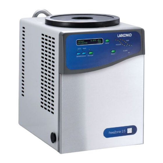
2.5 Liter Freeze Dry Systems
To receive important product updates,
complete your product registration card
online at register.labconco.com
Labconco Corporation
8811 Prospect Avenue
Kansas City, MO 64132-2696
800-821-5525, 816-333-8811
FAX 816-363-0130
E-MAIL
labconco@labconco.com
HOME PAGE www.labconco.com
Advertisement
Table of Contents

Subscribe to Our Youtube Channel
Related Manuals for Labconco FreeZone 76700 Series


Summary of Contents for Labconco FreeZone 76700 Series
- Page 1 2.5 Liter Freeze Dry Systems Models 74200 Series 76700 Series 76705 Series To receive important product updates, complete your product registration card online at register.labconco.com Labconco Corporation 8811 Prospect Avenue Kansas City, MO 64132-2696 800-821-5525, 816-333-8811 FAX 816-363-0130 E-MAIL labconco@labconco.com HOME PAGE www.labconco.com...
- Page 2 This limited warranty covers parts and labor, but not transportation and insurance charges. In the event of a warranty claim, contact Labconco Corporation or the dealer who sold you the product. If the cause is determined to be a manufacturing fault, the dealer or Labconco Corporation will repair or replace all defective parts to restore the unit to operation.
-
Page 3: Table Of Contents
ABLE ONTENTS CHAPTER 1: INTRODUCTION Freeze Dry Process Freeze Dry Rates Freeze Dry Capacity Samples Containing Volatile Substances About This Manual Typographical Conventions Your Next Step CHAPTER 2: PREREQUISITES Electrical Requirements Location Requirements Vacuum Pump Requirements Chamber or Manifold Requirements CHAPTER 3: GETTING STARTED Unpacking Your Freeze Dryer Freeze Dryer Components... - Page 4 Pre-Freezing Samples Adding Sample Shut Down Defrosting Alarms Power Failure Line Voltage Out of Range Temperature Out of Range Service Vacuum Pump Moisture in Collector CHAPTER 5: MAINTAINING YOUR FREEZE DRYER CHAPTER 6: USING THE RS232 RECEPTACLE Computer Connection for Computer Interface CHAPTER 7: TROUBLESHOOTING Vacuum Pump Gaskets, Tubing, Connections, Sample Valves...
-
Page 6: Chapter 1: Introduction
HAPTER NTRODUCTION Congratulations on your purchase of a Labconco FreeZone® Freeze Dry System, which is designed for laboratory lyophilization procedures. The refrigerant used in the refrigeration system is CFC-free so it will not endanger the environment. The unit is easy to install and maintain. Proper care and maintenance of this product will result in many years of dependable service. -
Page 7: Freeze Dry Rates
Chapter 1: Introduction Freeze Dry Rates The efficiency of the Freeze Drying process is dependent upon the surface area and the thickness of the sample, the collector temperature and vacuum obtained, the eutectic point and solute concentration of the sample. It is important to remember these factors when trying to obtain efficient utilization of your Freeze Dry system. -
Page 8: Freeze Dry Capacity
Chapter 1: Introduction efficient rate. In many applications, the maintenance of a vacuum of 0.133 mBar or less is recommended. The rate of freeze drying is directly proportional to the vapor pressure and the vapor pressure is dependent upon both eutectic temperature and solute concentration of the sample. -
Page 9: Samples Containing Volatile Substances
Chapter 1: Introduction Samples Containing Volatile Substances In certain cases the solvent in a sample to be freeze dried may contain volatile components such as acetonitrile, methanol, acetic acid, formic acid or pyridine. In addition to these substances having an effect on the eutectic temperature, they may increase the vapor pressure at the surface of the sample. -
Page 10: Typographical Conventions
Chapter 1: Introduction Appendix B: Freeze Dryer Dimensions contains comprehensive diagrams showing the dimensions for the Freeze Dryer. Appendix C: Freeze Dryer Specifications contains product specifications. Appendix D: Freeze Dryer Accessories lists the part numbers and descriptions of all of the accessories available for your Freeze Dryer. Typographical Conventions Recognizing the following typographical conventions will help you understand and use this manual:... -
Page 11: Chapter 2: Prerequisites
HAPTER REREQUISITES Before you install your Freeze Dryer, you need to prepare your site for installation. Carefully examine the location where you intend to install your Freeze Dryer. You must be certain that the area is level and of solid construction. An electrical source must be located near the installation site. -
Page 12: Vacuum Pump Requirements
See Appendix D: Freeze Dryer Accessories for vacuum pumps available from Labconco. Chamber or Manifold Requirements A freeze drying chamber or manifold is not included and must be purchased separately. -
Page 13: Chapter 3 Getting Started
HAPTER ETTING TARTED Now that the site for your Freeze Dryer is properly prepared, you are ready to unpack, inspect, install and test your Freeze Dryer. Read this chapter to learn how • unpack and move your Freeze Dryer. • set up your Freeze Dryer. •... -
Page 14: Unpacking Your Freeze Dryer
IF YOUR FREEZE DRYER WAS DAMAGED IN TRANSIT, YOU MUST FILE A CLAIM DIRECTLY WITH THE FREIGHT CARRIER. LABCONCO CORPORATION AND ITS DEALERS ARE NOT RESPONSIBLE FOR SHIPPING DAMAGE. DO NOT DISCARD THE CARTON OR PACKING MATERIAL FOR YOUR FREEZE DRYER UNTIL YOU HAVE CHECKED ALL OF THE COMPONENTS AND INSTALLED AND TESTED THE FREEZE DRYER. - Page 15 Chapter 3: Getting Started Power Cords PTFE Coated Catalog # Description Volts Chamber 7670520 2.5L Benchtop Freeze Dryer 7670521 2.5L Benchtop Freeze Dryer 7670530 2.5L Benchtop Freeze Dryer 7670531 2.5L Benchtop Freeze Dryer 7670540 2.5L Benchtop Freeze Dryer 7670541 2.5L Benchtop Freeze Dryer 7670560 2.5L Benchtop Freeze Dryer 7670561...
-
Page 16: Setting Up Your Freeze Dryer
Chapter 3: Getting Started If you did not receive one or more of the components listed for your Freeze Dryer, or if any of the components are damaged, contact Labconco Corporation immediately for further instructions. Setting Up Your Freeze Dryer After you verify receipt of the proper components, move your Freeze Dryer to the location where you want to install it. -
Page 17: Electrical Connection
Chapter 3: Getting Started TO MAXIMIZE THE STABILITY OF THE CONSOLE FREEZE DRYER, POSITION THE VACUUM PUMP AS CLOSE TO THE CENTER OF THE CABINET FLOOR AS POSSIBLE. Connect the vacuum pump power cord to the receptacle on the back of the cabinet labeled “vacuum pump.”... - Page 18 Chapter 3: Getting Started Acids Buffers Solvents Component Material Valve Stem Acetal Collector Acrylic Hoses, Neoprene Gaskets & Valve Bodies Flask Top Silicon Rubber Chamber & Stainless Fittings Steel C – Moderate degradation; Limited use D – Severe degradation; infrequent use recommended; immediate thorough cleaning required.
-
Page 19: Solvent Safety Precautions
Warranty on the affected parts will be voided if maintenance has been obviously neglected. If you have questions about using specific compounds in the Freeze Dryer, contact Labconco Technical Service at 1-800-821-5525 or 816-333- 8811 or e-mail: labconco@labconco.com. Solvent Safety Precautions Solvents used in the Freeze Dryer may be flammable or hazardous to your health. -
Page 20: Chapter 4: Using Your Freeze Dryer
HAPTER SING REEZE RYER After your Freeze Dryer has been installed as detailed in Chapter 3: Getting Started, you are ready to begin using your Freeze Dryer. Read this chapter to learn how to: • operate the controls. • understand the display. •... -
Page 21: Freeze Dryer Controls
Chapter 4: Using Your Freeze Dryer Freeze Dryer Controls The control panel for the Freeze Dryer is shown below with a description about its function. 1. LCD Display – Displays system operating parameters, set-up parameters and alarm messages. 2. Menu Switch – This switch is used to change the display from operating system parameters to set-up parameters. -
Page 22: Operation Checklist
Chapter 4: Using Your Freeze Dryer 11. Collector Temperature Graph Display – This display indicates the temperature of the collector. The highest LED indicates the collector temperature is warmer than 10°C. The indicators will sequence down when the temperature reaches 10, 0, -10, -20, -30, - 40°C. - Page 23 Chapter 4: Using Your Freeze Dryer To configure your Freeze Dryer, turn the main power switch ON and press MENU. The display will show: VACUUM UNITS mBar Torr • Press SELECT until the desired units are flashing. • Press MENU. •...
- Page 24 Chapter 4: Using Your Freeze Dryer • To reset the SERVICE HOUR to 0 press SELECT. This allows you to keep track of the time the refrigeration system operated since it was serviced. • The display will show the refrigeration system hours. REFRIG TOTAL HOUR: XXXX RESET SERVICE HOUR: ? •...
-
Page 25: Baffle
Chapter 4: Using Your Freeze Dryer Baffle The cylindrical plastic component shipped with Cascade Freeze Dryers (Models 76700XX and 74200X) is a baffle, which is designed to evenly distribute collected ice over the entire collector coil. Proper positioning of the baffle is required to achieve maximum ice loading capabilities. -
Page 26: Pre-Freezing Samples
Chapter 4: Using Your Freeze Dryer of the sample. Adjustments to the vacuum level must be made for various freeze drying conditions. Factors that must be considered are whether the sample is freeze dried on heated shelves or in glassware attached to manifold valves, the volatility of the sample itself, the size of the sample and the heat energy supplied to the sample. -
Page 27: Shut Down
Chapter 4: Using Your Freeze Dryer Bevel in “vent” position Vent/Backfill Port Bevel in “vacuum” position Adapter 2. Before adding another sample, allow system vacuum to return to 0.133 mBar or lower. Any combination of valves and sample sizes may be utilized at one time provided that the system vacuum and collector temperature remain sufficiently low to prevent melting of the frozen sample. -
Page 28: Defrosting
Chapter 4: Using Your Freeze Dryer LED to turn OFF the refrigeration system. Turn OFF the Main Power Switch on the right hand side of the cabinet. Defrosting The following procedure should be followed when defrosting the collector coil: 1. Pull the collector chamber drain hose out from the left hand side of the Freeze Dryer and remove the drain plug. -
Page 29: Line Voltage Out Of Range
Chapter 4: Using Your Freeze Dryer automatically restart. This prevents melted sample from being drawn into the collector and prevents liquid from being sucked into the vacuum pump. When power is restored, the alarm indicator will flash and the alarm beeper will sound. -
Page 30: Service Vacuum Pump
Chapter 4: Using Your Freeze Dryer Service Vacuum Pump The vacuum pump normally plugs into the vacuum pump electrical receptacle on the back of the Freeze Dryer. When the Freeze Dryer has accumulated a total of 1000 operating hours, the alarm indicator will flash. Press MENU to display the alarm: CHANGE VACUUM OIL HOLD SELECT TO CLEAR IT... -
Page 31: Chapter 5: Maintaining Your Freeze Dryer
HAPTER AINTAINING REEZE RYER Under normal operation, the Freeze Dryer requires little maintenance. The following maintenance schedule is recommended: As needed: 1. Clean up all spills; remove liquids from the chamber. 2. Clean lid and gasket using soft cloth, sponge or chamois and a mild, non- abrasive soap or detergent. - Page 32 Chapter 5: Maintaining Your Freeze Dryer Monthly: 1. The rubber components on the Freeze Dryer may eventually deteriorate and require replacement. The effective life of rubber parts depends upon both their usage and the surrounding environment. Check all rubber hoses and gaskets and replace any that show signs of hardening, permanent set or deterioration.
-
Page 33: Chapter 6: Using The Rs232 Receptacle
1. Computers with a 25 pin D-sub male serial connector should use Connect Cable, Labconco part number 7537801, to connect a computer to the Labconco Freeze Dryer. 2. Computers with a 9 pin D-sub male serial connector should use Connect Cable, Labconco part number 7537800, to connect a computer to the Labconco Freeze Dryer. - Page 34 Chapter 6: Using the RS232 Receptacle The time between data transmissions may be varied by the user to occur at 10, 30, 60, 300 or 600 second intervals. Press the MENU button until the RS232 screen appears on the display. RS-232 TRANSMISSION RATE SECONDS Press select until the desired time interval is shown.
- Page 35 Chapter 6: Using the RS232 Receptacle The first time Hyper Terminal™ is opened a dialogue box requesting an area code and phone number will appear. Enter the appropriate numbers and continue. 3. The “Connection Description” dialogue box will open. Type in a user defined name and select an icon for the new connection.
- Page 36 Chapter 6: Using the RS232 Receptacle 5. The “Com X Properties” dialogue box will open. Enter the appropriate data properties and press “OK.” 6. When the Freeze Dryer main power switch is on, the data will be transmitted and updated at the time intervals selected by the user. Product Service 816-333-8811 or 1-800-522-7658...
-
Page 37: Chapter 7: Troubleshooting
Labconco for additional assistance. Labconco Freeze Dry Systems that are clean, dry and without samples attached should reach a vacuum of 0.133 mBar within 10 minutes and should achieve an ultimate vacuum of 0.040 mBar within 18 hours when the refrigeration is operating. -
Page 38: Ii. Gaskets, Tubing, Connections, Sample Valves
Chapter 7: Troubleshooting 4. Isolate the pump by disconnecting the vacuum hose from the Freeze Dryer. Deadhead the pump by inserting the vacuum sensor from a secondary vacuum gauge into the end of the vacuum hose and observe the vacuum reading obtained. - Page 39 Chapter 7: Troubleshooting The illustrations below show how the sample valve installs on a chamber and a manifold. Knob & Stem Assembly Valve Body Valve Assembly (Clear Chamber with Valves) Bulkhead Nut Valve Body Manifold Assembly Thrust Washer Valve Body Thrust Washer Gasket Knob &...
-
Page 40: System Components & Collection Chamber Isolation
Chapter 7: Troubleshooting III. System Components and Collection Chamber Isolation This test determines if the source of a leak is in the drying chamber. 1. Remove the drying chamber or manifold. 2. Leave the gasket on and turn a large freeze dry flask upside down to cover the connection port. - Page 41 Chapter 7: Troubleshooting The following test determines if a vacuum leak is in the collection chamber. 1. Insert a rubber stopper in the small hole in the rear of the collector chamber and another in the drain port in the bottom. 2.
-
Page 42: Refrigeration Module Operation
If any repairs are required on the refrigeration module, contact your local laboratory supply dealer. If your laboratory supply dealer is unable to provide assistance, please call Labconco. Repairs should only be undertaken by a competent refrigeration technician or through an authorized Labconco service agency. -
Page 43: Chapter 8: Modifying Your Freeze Dryer Display
HAPTER ODIFYING REEZE RYER ISPLAY Your Freeze Dryer has been carefully calibrated and tested before shipping, however under certain circumstances it may be necessary to adjust the calibration of the temperature and/or vacuum display or to modify alarm points. Adjustments may be necessary if the Freeze Dryer requires service or if it is operating on a line voltage outside the voltage range at which the alarm was preset. -
Page 44: Moisture Sensor Alarm
Chapter 8: Modifying Your Freeze Dryer Display High line limit may be raised in 5 increments of approximately 2 to 3V increments for 115V models or disabled. High line limit may be raised in 5 increments of approximately 4 to 5V increments for 230V models or disabled. - Page 45 Chapter 8: Modifying Your Freeze Dryer Display Press MENU and if the drying chamber has been installed, the display will show: SDC TEMP. OFFSET: Press SELECT until the appropriate offset is shown. Each number represents 1°C. Press MENU and the display will show: VACUUM OFFSET: O uBar Press SELECT until the appropriate offset is shown.
- Page 46 Chapter 8: Modifying Your Freeze Dryer Display Press MENU and the display will show: PURGE VALVE: NOT INSTALLED Press and hold SELECT to change the status. Press MENU and the display will show: DEFROST HEATER: NOT INSTALLED Press and hold SELECT to change the status. Press MENU and the display will show: MOISTURE SENSOR: INSTALLED...
- Page 47 Chapter 8: Modifying Your Freeze Dryer Display In order to store offsets in memory, you Must Press and Hold MENU until display shows: PASSWORD: Wait approximately 10 seconds and the display will default to the main freeze dry display information. This can be done anytime throughout the Modifying the Display routine.
-
Page 48: Appendix A: Freeze Dryer Components
PPENDIX REEZE RYER OMPONENTS The following pages list components that are available for your Freeze Dryer. The parts shown are the most common replacement parts. If other parts are required, contact Product Service. Product Service 1-800-522-7658... - Page 49 Appendix A: Freeze Dryer Components Model 76705xx Item Part No. Description 7395800 Lid Gasket 7395801 7435800 Back Panel Assembly, 115V 7435900 Back Panel Assembly, 230V 7953800 Motor Fan, 115V 7953801 Motor Fan, 230V 7591805 Compressor, 115V, 60 Hz 7591806 Compressor, 230V, 50 Hz 7591807 Compressor, 230V, 60 Hz 1302300...
- Page 50 Appendix A: Freeze Dryer Components Model 76705xx 9-10 Product Service 816-333-8811 or 1-800-522-7658...
- Page 51 Appendix A: Freeze Dryer Components Models 76700xx and 74200xx Item Part No. Description 7395800 Lid Gasket 7395801 7435800 Back Panel Assembly, 115V 7435900 Back Panel Assembly, 230V 7953800 Motor Fan, 115V 7953801 Motor Fan, 230V 7591805 Compressor, 115V, 60 Hz Lo Stage 7591806 Compressor, 230V, 50 Hz Lo Stage 7591807...
- Page 52 Appendix A: Freeze Dryer Components Models 76700xx and 74200xx 9-10 Product Service 816-333-8811 or 1-800-522-7658...
-
Page 53: Appendix B: Freeze Dryer Dimensions
PPENDIX REEZE RYER IMENSIONS Model 76705xx Product Service 1-800-522-7658... - Page 54 Appendix B: Freeze Dryer Dimensions Model 76700xx Product Service 816-333-8811 or 1-800-522-7658...
- Page 55 Appendix B: Freeze Dryer Dimensions Model 74200xx Product Service 816-333-8811 or 1-800-522-7658...
-
Page 56: Appendix C: Freeze Dryer Specifications
PPENDIX REEZE RYER PECIFICATIONS This Appendix contains technical information about the Freeze Dryer including electrical specifications and operating conditions. Electrical Specifications Catalog # Voltage Frequency Phase Amperage Nominal Max. with Operating Nominal Vacuum Range Vacuum Pump Pump 7670520 115V 103-127 100V 90-110 7670521... -
Page 57: Environmental Conditions
Appendix C: Freeze Dryer Specifications Catalog # Voltage Frequency Phase Amperage Nominal Max. with Operating Nominal Vacuum Range Vacuum Pump Pump 7420020 115V 103-127 10.0 100V 90-110 10.0 7420021 115V 103-127 10.0 100V 90-110 10.0 7420030 230V 198-254 7420031 230V 198-254 7420040 230V... -
Page 58: Appendix D Freeze Dryer Accessories
PPENDIX REEZE RYER CCESSORIES The following accessories are available for the Freeze Dryer. PART # DESCRIPTION 1472100 Vacuum Pump Two stage direct drive pump, 117 liters/minute. 115 VAC, 50/60 Hz, single phase, 4.6 amps. Includes Pump Exhaust Filter 1473400. (Cat. # 1473400) 7739402 Vacuum Pump Two stage direct drive pump, 117 liters/minute. - Page 59 Appendix D: Freeze Dryer Accessories PART # DESCRIPTION 1472200 Pump Inlet Filter Disposable filter that prevents oil back streaming and protects vacuum pump from submicron particles. Fits vacuum pumps 1472100 and 7739402. 1473400 Pump Exhaust Filter Disposable filter that removes visible oil mist and odor from vacuum pump exhaust.
- Page 60 Appendix D: Freeze Dryer Accessories PART # DESCRIPTION 7772500 Carbon Solvent Trap Secondary trap that prevents migration of organic solvents into vacuum pump. 7772600 Replacement Activated Carbon Media for Carbon Solvent Trap 7538000 Secondary Vacuum Cold Trap Provides additional protection for the vacuum pump when processing low eutectic samples.
- Page 61 Appendix D: Freeze Dryer Accessories PART # DESCRIPTION 7868500 48 Port Ampule Manifold 28 5/8" high x 5" wide x 5" deep. Type 304 stainless steel with 48 each ¼" tube stems. 7509600 Sample Valve Kit Includes neoprene valve body, knob and installation parts. 7522900 16 Port Drying Chamber 13"...
- Page 62 Appendix D: Freeze Dryer Accessories Product Service 816-333-8811 or 1-800-522-7658...
- Page 63 Appendix D: Freeze Dryer Accessories Product Service 816-333-8811 or 1-800-522-7658...
- Page 64 Appendix D: Freeze Dryer Accessories Product Service 816-333-8811 or 1-800-522-7658...
- Page 65 Appendix D: Freeze Dryer Accessories Ampules Product Service 816-333-8811 or 1-800-522-7658...
Need help?
Do you have a question about the FreeZone 76700 Series and is the answer not in the manual?
Questions and answers