Advertisement
Quick Links
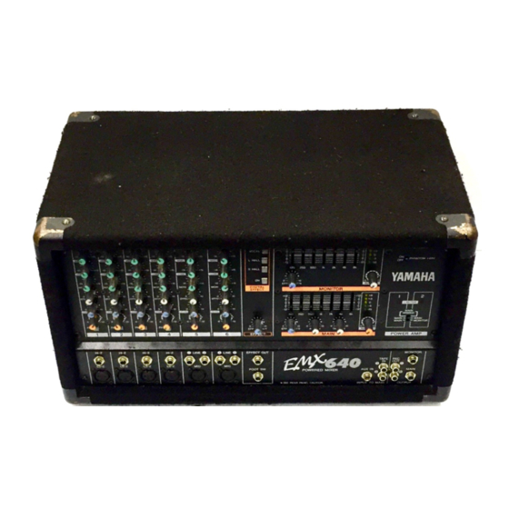
POWERED MIXER
1. Avoid excessive heat, humidity, dust and vibration
2. Ventilation
3. Avoid physical shocks
4. Do not open the case or attempt repairs or modifications
yourself
Front and rear panel ............................................ 2
Control panel .......................................................... 2
Input/output panel .................................................. 6
Rear panel .............................................................. 7
Connections ......................................................... 8
Basic Operation ................................................... 9
Connecting microphones and instruments ............ 9
Using the digital effect ............................................ 9
Example setups ................................................. 10
As a conference PA system/installed sound system 10
As a band PA ........................................................ 11
Specifications ..................................................... 13
General specifications .......................................... 13
Input specifications ............................................... 14
Output specifications ............................................ 14
Dimensions ........................................................... 15
Block and Level diagram ...................................... 15
5. Always power off before making connections
6. Handle cables carefully
7. Clean with a soft dry cloth
8. Always use the correct power supply
9. Do not touch the heatsink when the EMX640 is in use.
It can get very hot.
E
Advertisement

Related Manuals for Yamaha EMX 640


Summary of Contents for Yamaha EMX 640
- Page 1 POWERED MIXER Front and rear panel ..........2 Control panel ............2 Input/output panel ..........6 Rear panel .............. 7 Connections ............8 Basic Operation ........... 9 Connecting microphones and instruments .... 9 Using the digital effect ..........9 Example setups ..........10 As a conference PA system/installed sound system 10 As a band PA ............
- Page 2 ■ HIGH –15 –15 –15 MONI EFFECT LEVEL ▼ ± ± ±...
- Page 3 ■ ■ VOCAL L HALL EFFECT OUT S HALL EFFECT DIGITAL EFFECT...
- Page 4 ■ ■ • • • • • • • • –5 • • • • –12 –10 • • –12 –5 • • –12 –12 –10 EFFECT RTN AUX IN TAPE IN MASTER MAIN EFFECT RTN MASTER MONITOR ± ±...
-
Page 5: Power Amp
■ ■ POWER PHANTOM +48V LIMITER MAIN BRIDGE MAIN MAIN MAIN MONITOR POWER AMP... - Page 6 Hi-Z Hi-Z Hi-Z Hi-Z LINE LINE EFFECT OUT MONITOR TAPE Lo-Z Lo-Z Lo-Z Lo-Z FOOT SW AUX IN MAIN INPUT TO MAIN OUTPUT SEE REAR PANEL CAUTION Ω Ω Ω Ω Lo-Z jacks Hi-Z jacks (XLR type) (TRS phone jacks) Ω...
- Page 7 Ω Ω Ω Ω SPEAKERS POWER AMP 2 BRIDGE POWER AMP 1 POWER ON / Ω Ω Ω...
- Page 8 ■ SPEAKERS SPEAKERS SPEAKERS POWER AMP 2 BRIDGE POWER AMP 1 POWER AMP 2 BRIDGE POWER AMP 1 POWER AMP 2 BRIDGE POWER AMP 1 POWER POWER POWER ON / ON / ON / Ω Ω Ω Ω Ω Ω Ω...
- Page 9 ➞...
- Page 10 HIGH HIGH HIGH H IG H HIG H HIG H POWER • • VOCAL • • –15 –15 –15 –15 –15 –15 • • L HALL –5 PHANTOM +48V • • –10 –12 –12 S HALL –15 –15 –15 –15 –15 –15 LO W...
- Page 11 H IGH HIG H HIG H HIG H HIGH HIGH POWER VOCAL • • • • –15 –15 –15 –15 –15 –15 • • –5 PHANTOM +48V L HALL • • –12 –12 –10 –15 –15 –15 –15 –15 –15 S HALL LO W L OW...
- Page 13 ■ Maximum output power 200 W/4Ω @0.5% THD at 1 kHz 20 Hz~20 kHz +1 dB, –3 dB @1 W output into 8Ω (POWER AMP OUT) Frequency response 20 Hz~20 kHz +1 dB, –3 dB @+4 dB output into 10 kΩ (MAIN OUT, MONITOR OUT, EFFECT SEND) Less than 0.5% @20 Hz~20 kHz, 100 W output into 4Ω...
- Page 14 ■ Input level Actual load Nominal Connector Input connectors impedance impedance Max. before type Nominal level Sensitivity cliping 50~600Ω Mics –62 dB (616 µV) –50 dB (2.45 mV) –20 dB (77.5 mV) CH INPUT (Lo-Z) 3 kΩ XLR-3-31 type (CH1~4) 600Ω...
- Page 15 ■ W: 480 Unit: mm ■ PHANTOM +48V Lo-Z LEVEL 1–4 LIMITER MAIN MASTER Hi-Z EFFECT MONI POWER AMP 1 MAIN BRIDGE LEVEL REC OUT MAIN MAIN 5, 6 MAIN MONITOR LIMITER BRIDGE EFFECT LINE MONI POWER AMP 2 AUX IN AUX IN MONITOR MASTER...
-
Page 16: Fcc Information (U.s.a.)
ACCORDANCE WITH THE FOLLOWING CODE: this manual, meets FCC requirements. Modifications not expressly GREEN-AND-YELLOW : EARTH approved by Yamaha may void your authority, granted by the FCC, to use the product. BLUE : NEUTRAL BROWN : LIVE 2.
Need help?
Do you have a question about the EMX 640 and is the answer not in the manual?
Questions and answers