Table of Contents
Advertisement
Quick Links
Advertisement
Table of Contents

Subscribe to Our Youtube Channel
Related Manuals for Entes EMM Series

Summary of Contents for Entes EMM Series
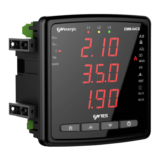
- Page 1 EMM Series Multimeters User Manual www.entes.com.tr...
-
Page 2: Table Of Contents
Index Introduction ......................3 Safety and warnings ..................3 General Specifications ..................3 Mechanical and Environmental Conditions ............4 Standards ......................4 Technical Specifications ................... 4 Connection Diagram ..................6 LED Indicator and GUI design ................9 Key Functions ....................9 Measurement ....................... -
Page 3: Introduction
Introduction Safety and Warnings Caution Failure to follow the instructions below may result in serious injuries or even death.. • Disconnect all power when installing the device. • Do not remove the front panel while the device is connected to the mains. •... -
Page 4: Mechanical And Environmental Conditions
Mechanical and Environmental Conditions Operating Conditions Value Range Dimensions 96x96 Maximum Depth 44.5 mm (Inside the Panel) Installation Panel type IP protection Display LED display Button 4 x Universal interface Storage Temperature -30 / +80°C Operating Temperature -20 / +70°C Maximum Humidity 95% (noncondensing) Standards... - Page 5 Parameter Unit Description Range Sensitivity Maximum Value Voltage V1, V2, V3 Phase-Neutral, Rms Voltage 10-300 VAC 0,5% 6 MV U1, U2, U3 Phase-Phase, Rms Voltage 10-480 VAC 0,5% 9.6 MV Frequency Voltage Frequency 50-60 Hz ±0.02 Hz Current I1, I2, I3 Phase Current 0.05-5.5 A 10kA...
-
Page 6: Connection Diagram
Connection Diagram 2- Relay Outputs 1- Voltage Inputs 3- Auxiliary Supply Input 4- Current Inputs 5- RS-485 Terminal Structure; Connection Range Klemens Tipi Voltage Inputs 3 x 10 – 480 VAC 50/60Hz 4 x 7.62 mm socket 2.5 mm², 4 mm² Relay Outputs 2 x 250 VAC 5A 1250 VA 4 x 5.08 mm socket... - Page 7 1. 3P4W (Three-Phase Four-Wire) Connection In this type of connection, three voltage and three current connections are made. GND B(-) A(+) 2. 3P3W (Three-Phase Three-Wire) Connection In this type of connection, three voltage and three current connections are made. GND B(-) A(+) 3.
- Page 8 4. 3P4W BLN (Three-Phase Four-Wire Balanced) Connection In this type of connection, four voltage and one current connections are made. The device displays the value measured at the current input connected to the first phase on the screen of the same value for other phases.
-
Page 9: Led Indicator And Gui Design
LED Indicator and GUI design Key Functions Phase 1 / 2 / 3 LEDs It informs you that voltage is taken from the phases. (e.g. LED L1 lights up if voltage is being taken from phase L1.) VLN Measurement LED It lights up when the screen showing phase-neutral voltages is on VLL Measurement LED It lights up when the screen showing phase-phase voltages is on... -
Page 10: Measurement
Measurement Voltage This screen shows the phase-neutral voltage values for each phase. You can see Min Voltage (Phase-Neutral) and Max Voltage (Phase-Neutral) values by pressing the OK button. Depending on the connection type in the Phase-Neutral voltage (3P3W, 3P3W balance and Aron), this screen will not be displayed. -
Page 11: Current
Current Instantly measured current values for each phase are displayed on this screen. You can see Min Voltage (Phase-Neutral), Max Current (Phase-Neutral), Demand (Phase-Neutral) and Max Demand (Phase-Neutral) values by pressing the OK button. Neutral Current This screen shows the calculated neutral current value. You can see the Min and Max values by pressing the OK button. -
Page 12: Frequency
Frequency You can see the operating frequency of the device on this screen. Cos Phi You can see cos phi values of each phase separately on this screen. Total Cos Phi You can see total cos phi values on this screen. -
Page 13: Total Run Hour
Total Run Hour It is the screen on which the run hour of this device is displayed. You can view the time it has worked since the first power-up on the screen. The value on the screen increases by 1 in 3.6 seconds. If you multiply the value on the screen by 3.6, you can reach the total operating time. -
Page 14: Settings
Settings Press and hold OK to access the settings menu. If you wish to do something under the Settings menu or change the settings, press OK to go to menu details and change Product or User settings under the Settings menu. In the Settings menu, the symbols in the right corner of the screen indicate which setting you are in. -
Page 15: Password Setting
Password Setting On this screen, you can set the password that you will use for the security of the device. The current password is entered on the first screen. If it is entered correctly, the screen for entering the new password will be displayed. The screen for re-entering the password is displayed to confirm the new password. -
Page 16: Connection Type
Connection Type... -
Page 17: Frequency
Frequency Demand Period (Based on Model) -
Page 18: Voltage Transformer Setting
Voltage Transformer Setting In this screen, you can configure the voltage transformer settings. If you are using a voltage transformer, you must set the setting to on and then enter the primary and secondary values. -
Page 19: Current Transformer Setting
Current Transformer Setting It is the menu in which the primary and secondary values for the current transformer are entered. You will be prompted to enter CT Primary and CT Secondary values respectively. Communication Settings Communication and Modbus RTU settings of the device are made in this menu. Modbus address, bit rate, parity bit settings of the device are made in this menu (For models without communication, this screen will not be available). - Page 20 Modbus Address: This parameter can be set to a value between 1 and 247. The value set must be unique on the line where the product is found. Otherwise, communication of the line, to which the product is connected, will be disrupted. Bit Rate: This parameter can be set to one of the following values: 2400, 4800, 9600, 19200, 38400, 57600, 115200 or 256000 bps.
-
Page 21: Output Settings
Output Settings On this screen, you can configure the output settings of the device. Relay 1 Press the OK button to configure the relay setting. Then select the setting parameter. Setting parameter can be selected as Relay or RS-485. If the setting is selected as a relay, the relay is activated when an alarm condition occurs (if the alarm output is assigned as a relay). -
Page 22: Alarm Settings
Alarm Settings User Mode It is the screen where the user mode is selected. The user mode can be selected as simple or advanced. In the advanced user mode, the following parameters are activated (varies by parameter). Hysteresis is only available in the measurement parameters. •... - Page 23 Custom alarm Press the OK button to program a custom alarm. Then select a parameter. Parameter selection varies by device model. You can set alarm by selecting Voltage, Current, Current demand, Frequency, Cos Phi, Total work time and work time. For example, the voltage alarm setup is as follows.
- Page 24 Press the OK button to make an operation selection. Select the large or small operation. Then press the OK button and enter a value.
- Page 25 Enter the hysteresis value and press the OK button. Enter the on delay and press the OK button. Enter the off delay and press the OK button.
- Page 26 Select the output feature on the device with output options. When this option is selected, there is no output on the device. When Rly 2 is selected, relay number 2 is activated in case of alarm. When Rly 1 is selected, relay number 1 is activated in case of alarm.
- Page 27 Press the OK button to select the function. In standard mode, the relay is activated when an alarm occurs. In Latch mode, the relay is activated when the alarm actuates, but when the alarm disappears, the relay remains on. You must hold the down button to return the relay to its normal state. In Inverse mode, the relay is released if it is activated, or it is activated if it is released.
- Page 28 Reset On this screen, you can reset the device to factory settings by pressing the OK button. On this screen, you can reset the work time by pressing the OK button. On this screen, you can reset the MAX Demand by pressing the OK button. On this screen, you can reset the MAX by pressing the OK button.
- Page 29 On this screen, you can reset the MIN by pressing the OK button. On this screen, you can reset the work time by pressing the OK button. The total work time cannot be reset. Info In the Info menu, you can view the following information about the device. Hardware Version...
- Page 30 Software Version Serial No Run Hour In this menu, you can set the work time for Current or Current Demand.
-
Page 31: Alarm Messages
Alarm Messages When an alarm occurs on your device, the alarm appears on the screen. You can delay the alarms by pressing the OK button for the duration of the delay time setting. When critical alarms occur, Relay 1 is activated. No Voltage is measured It occurs when any phase has no voltage. - Page 32 Phase Sequence It occurs when the phases are not connected in the correct order. Custom Alarm It appears on the screen when any of 8 special alarms actuate. The alarm number is displayed on the screen.
Need help?
Do you have a question about the EMM Series and is the answer not in the manual?
Questions and answers