Table of Contents
Advertisement
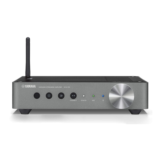
WIRELESS STREAMING AMPLIFIER/
WIRELESS STREAMING PRE-AMPLIFIER
WXA-50/WXC-50
Note: WXA-50: U, C, V, S models
When replacing the "amplifier and power module" of this unit with a new service part, make sure to replace the "jumper wire" for
switching the input voltage located on the P.C.B. of the "amplifier and power module".
For details, refer to "DISASSEMBLY PROCEDURES: 6. Removal of Amplifier and Power Module".
注意: WXA-50
本機の "アンプ/電源モジュール" を新しいサービスパーツに交換する場合、必ず "アンプ/電源モジュール" の基板上にある入
力電圧切替の "ジャンパー線" を入れ替えてください。
詳細は、"分解手順:6. アンプ/電源モジュールの外し方" を参照してください。
This manual has been provided for the use of authorized Yamaha Retailers and their service personnel.
It has been assumed that basic service procedures inherent to the industry, and more specifi cally Yamaha Products, are already known
and understood by the users, and have therefore not been restated.
WARNING:
IMPORTANT:
The data provided is believed to be accurate and applicable to the unit(s) indicated on the cover. The research, engineering, and service
departments of Yamaha are continually striving to improve Yamaha products. Modifi cations are, therefore, inevitable and specifi cations
are subject to change without notice or obligation to retrofi t. Should any discrepancy appear to exist, please contact the distributor's
Service Division.
WARNING:
IMPORTANT:
■ CONTENTS
To Service Personnel ............................................2
Front Panels .............................................................4
Rear Panels ...............................................................6
Remote Control Panel ..........................................9
SPECIFICATIONS / 参考仕様 ....................................... 10
Internal View .......................................................... 14
SERVICE PRECAUTIONS / サービス時の注意事項 ..... 14
DISASSEMBLY PROCEDURES / 分解手順 ................. 15
ファームウェアのアップデート ..................................23
1 0 1 3 7 6
SERVICE MANUAL
IMPORTANT NOTICE
Failure to follow appropriate service and safety procedures when servicing this product may result in personal injury,
destruction of expensive components, and failure of the product to perform as specifi ed. For these reasons, we advise
all Yamaha product owners that any service required should be performed by an authorized Yamaha Retailer or the
appointed service representative.
The presentation or sale of this manual to any individual or fi rm does not constitute authorization, certifi cation or
recognition of any applicable technical capabilities, or establish a principle-agent relationship of any form.
Static discharges can destroy expensive components. Discharge any static electricity your body may have
accumulated by grounding yourself to the ground buss in the unit (heavy gauge black wires connect to this buss).
Turn the unit OFF during disassembly and part replacement. Recheck all work before you apply power to the unit.
SELF-DIAGNOSTIC FUNCTION /
ダイアグ(自己診断機能) ...........................................26
Ic Data .........................................................................30
Block DiagramS ......................................................34
Wiring Diagram .......................................................37
Printed Circuit Boards .......................................38
Pin Connection DiagramS ...................................46
Schematic Diagrams .............................................47
Replacement Parts List ......................................53
REMOTE CONTROL ..................................................... 74
Copyright (c) Yamaha Corporation All rights reserved.
This manual is copyrighted by Yamaha and may not be copied or
redistributed either in print or electronically without permission.
P.O.Box 1, Hamamatsu, Japan
'16.07
Advertisement
Table of Contents

Related Manuals for Yamaha WXA-50


Summary of Contents for Yamaha WXA-50
-
Page 1: Important Notice
This manual has been provided for the use of authorized Yamaha Retailers and their service personnel. It has been assumed that basic service procedures inherent to the industry, and more specifi cally Yamaha Products, are already known and understood by the users, and have therefore not been restated. -
Page 2: To Service Personnel
WXA-50/WXC-50 ■ TO SERVICE PERSONNEL AC LEAKAGE WALL EQUIPMENT TESTER OR 1. Critical Components Information OUTLET UNDER TEST EQUIVALENT Components having special characteristics are marked ⚠ and must be replaced with parts having specifications equal to those originally installed. 2. Leakage Current Measurement (For 120V Models Only) - Page 3 WXA-50/WXC-50 About lead free solder / 無鉛ハンダについて All of the P.C.B.s installed in this unit and solder joints are 本機に搭載されているすべての基板およびハンダ付けに soldered using the lead free solder. よる接合部は無鉛ハンダでハンダ付けされています。 Among some types of lead free solder currently available, 無鉛ハンダにはいくつかの種類がありますが、修理時に it is recommended to use one of the following types for は下記のような無鉛ハンダの使用を推奨します。...
-
Page 4: Front Panels
WXA-50/WXC-50 ■ FRONT PANELS WXA-50 Top view Front view... - Page 5 WXA-50/WXC-50 WXC-50 Top view Front view...
-
Page 6: Rear Panels
WXA-50/WXC-50 ■ REAR PANELS WXA-50 U, C, K, A, B, G, L, V, S, J models Labels T model Label Labels U, C models T model... - Page 7 WXA-50/WXC-50 K model A, B, G, L models V, S models J model...
- Page 8 WXA-50/WXC-50 WXC-50 U, C, K, A, B, G, L, V, S, J models Labels Labels U, C models K model A, B, G, L models...
-
Page 9: Remote Control Panel
WXA-50/WXC-50 V, S models J model ■ REMOTE CONTROL PANEL... -
Page 10: Specifications
..............IEEE802.11b/g/n Supported Frequency / 対応再生周波数 Radio Frequency / 無線周波数 ..............32 kHz to 192 kHz ................... 2.4 GHz Speaker Output / スピーカー出力 [WXA-50] Supported Security / 対応セキュリティー Front ..............SPEAKERS L/R ........WEP, WPA2-PSK (AES), Mixed mode Pre-Out / プリアウト (volume enable) WPS (Wi-Fi Protected Setup) Function / ................SUBWOOFER... - Page 11 無信号時消費電力(参考値) [WXC-50] ..............112 dB [WXA-50] AUX IN ................98 dB ..................15 W [WXC-50] Channel Separation / チャンネルセパレーション ..................5 W (1 kHz / 10 kHz) [WXA-50] .............. 90 dB / 72 dB [WXC-50] ............. 95 dB / 85 dB...
- Page 12 Power cable (1.5 m) (U, C, T, A, B, G, L, V, J models) ..x 1 Bluetooth SIG, Inc. and any use of such marks by Yamaha Corporation is (1.8 m) (K, S models) ........x 1 under license.
- Page 13 WXA-50/WXC-50 Copyright 1999-2014 OpenSynergy GmbH All rights reserved. All unpublished rights reserved. 「ラジコ」 「radiko」および radiko ロゴは株式会社 radiko の登録商標です。 MusicCast is a trademark or registered trademark of Yamaha Corporation. MusicCast はヤマハ株式会社の商標または登録商標です。 • DIMENSIONS / 寸法図 WXA-50 WXC-50 Top view Top view 19.5...
-
Page 14: Internal View
■ INTERNAL VIEW Top view MAIN (5) P.C.B. (WXA-50) MAIN (4) P.C.B. (WXC-50) MAIN (2) P.C.B. MAIN (6) P.C.B. NETWORK MODULE AMPLIFIER AND POWER MODULE (WXA-50) MAIN (1) P.C.B. MAIN (3) P.C.B. Front view ■ SERVICE PRECAUTIONS / サービス時の注意事項 Safety measures 安全対策... -
Page 15: Disassembly Procedures
WXA-50/WXC-50 ■ DISASSEMBLY PROCEDURES / 分解手順 (Remove parts in the order as numbered.) (番号順に部品を外してください。 ) Disconnect the power cable from the AC outlet. AC 電源コンセントから、電源コードを抜いてください。 1. Removal of Top Cover (Fig. 1) 1. トップカバーの外し方(Fig. 1) Remove 4 screws ( ① ). - Page 16 WXA-50/WXC-50 2. Removal of Rear Cover (Fig. 2) 2. リアカバーの外し方(Fig. 2) WXA-50 WXA-50 Remove 3 screws ( ② ) and 3 screws ( ③ ). a. ② のネジ 3 本、③ のネジ 3 本を外します。 b. Remove the rear cover. b. リアカバーを外します。 WXC-50 WXC-50 Remove 4 screws ( ② ) and 3 screws ( ③ ).
- Page 17 WXA-50/WXC-50 3. Removal of MAIN (2) P.C.B. (Fig. 3) 3. MAIN(2)P.C.B. の外し方(Fig. 3) Remove screw ( ④ ). a. ④ のネジ 1 本を外します。 b. Pull out the MAIN (2) P.C.B. b. MAIN(2)P.C.B. を引き出します。 Remove CB501 and CB603. c. CB501、CB603 を外します。 d. Remove the MAIN (2) P.C.B. together with the barrier d. ...
- Page 18 WXA-50/WXC-50 • The wireless LAN antenna connector should only be ・ 無線 LAN アンテナコネクターは、ネットワークモ plugged back to the network module after it has been ジュールを MAIN(1)P.C.B. に取り付けてからネット installed back onto the MAIN (1) P.C.B. ワークモジュールへ挿すようにしてください。 • When plugging the wireless LAN antenna connector ・...
- Page 19 Remove screw ( ⑦ ) and remove the barrier shield. c. ⑧ のネジ 2 本、⑨ のネジ 3 本を外します。 Remove 2 screws ( ⑧ ) and 3 screws ( ⑨ ). d. WXA-50 d. WXA-50 CB1、CB2、P100、P102、P103 を外します。 Remove CB1, CB2, P100, P102 and P103.
- Page 20 WXA-50/WXC-50 6. Removal of DC Fan Motor and Amplifier and 6. DC ファンモーター、アンプ/電源モジュールの Power Module (Fig. 7) [WXA-50] 外し方(Fig. 7) [WXA-50] Remove 2 screws ( ⑩ ). a. ⑩ のネジ 2 本を外します。 b. Remove CB901. b. CB901 を外します。 Remove the DC fan motor together with the fan c. ...
- Page 21 WXA-50/WXC-50 7-1. Removal of MAIN (5) P.C.B. (Fig. 8) [WXA-50] 7-1.MAIN(5)P.C.B. の外し方(Fig. 8) [WXA-50] The barrier sheet is removed in advance as ※ バリアシートは MAIN(1)P.C.B.、電源モジュールの described in the MAIN (1) P.C.B. and power module 外し方の手順で先に外しています。 removal procedure. However, if the MAIN (5) P.C.B.
- Page 22 WXA-50/WXC-50 8. Removal of Front Panel (Fig. 10) 8. フロントパネルの外し方(Fig. 10) Remove the knob. a. ツマミを外します。 b. Remove 2 screws ( ⑯ ). b. ⑯ のネジ 2 本を外します。 Remove the front panel to the front. c. フロントパネルを前方に外します。 * Note that the front panel and front base are attached ※ フロントパネルとフロントベースが両面テープで...
-
Page 23: Updating Firmware
WXA-50/WXC-50 ■ UPDATING FIRMWARE / ファームウェアのアップデート When the following parts are replaced, the firmware must 下記の部品を交換した場合、ファームウェアを最新バー be updated to the latest version. ジョンにアップデートする必要があります。 MAIN P.C.B. MAIN P.C.B. Network module (NW-01) ネットワークモジュール(NW-01) ● Confirmation of firmware version and checksum ● ファームウェアのバージョンとチェックサムの確認 Before and after updating the firmware, check the ファームウェアのアップデートの前後に、ファーム... -
Page 24: Operation Procedures
WXA-50/WXC-50 ● Operation Procedures ● 操作手順 Disconnect the power cable of this unit from the ※ 電源コードを AC コンセントから抜きます。 AC outlet. 1. Insert the USB storage device to the USB jack. 1. USB 端子に USB フラッシュメモリーを差し込みま (Fig. 1) す。 (Fig. 1)... - Page 25 WXA-50/WXC-50 List of firmware writing error display / ファームウェア書き込みエラー表示一覧 Lit color / 点灯色 Number of flashing Condition STATUS (Bluetooth) 点滅回数 状態 Twice / 2 回 USB device error Red / 赤 Green / 緑 Blue / 青 USB デバイスエラー 3 times / 3 回...
- Page 26 Front view / 前面 " " (Power) key " "(電源)キー Search “WXA-50” or “WXC-50” within the “Network” of 2. PC の “ネットワーク” 内で “WXA-50” または “WXC-50” the PC and click on it. を検索してクリックします。 The Internet Explorer will be activated and the main インターネットエクスプローラーが起動し、メイン...
- Page 27 WXA-50/WXC-50 As the IP address of this unit appears on the address 3. アドレスバーに表示された本機の IP アドレスの後ろ bar, enter “/service_info” following the IP address and へ “/service̲info” を入力し、 [ Enter]キーを押します。 press the [Enter] key. “Device Information” が表示されます。 Then, “Device Information” will appear.
- Page 28 (Day / Hour / Minute) (日/時/分) PR On : 47 POWER-RELAY ON: POWER-RELAY ON: The operation frequency of the power relay 電源リレー(RY501)の動作回数が表示 (RY501) is displayed. (WXA-50) されます。 (WXA-50) OUTPUT VOLUME LEVEL: Out LVL Max : 0 OUTPUT VOLUME LEVEL: The maximum value of the speaker output スピーカー出力レベルの最大値が、スピー...
- Page 29 WXA-50/WXC-50 AMP/POWER MODULE T Out : 0 / 0 / 0 AMP/POWER MODULE POWER OFF TIME OUT: POWER OFF TIME OUT: The number of time-out times of アンプ/電源モジュールの電源オフ時に the amplifier and power module when タイムアウトした回数が表示されます。 the power is turned off will be displayed. Usage:...
- Page 30 WXA-50/WXC-50 ■ IC DATA IC1: TMPM462F15FG (ADBB) (MAIN (1) P.C.B.) CMOS 32-bit microprocessor * No replacement part available. / サービス部品供給なし Cortex-M4F FLASH NVIC Backup BOOT μDMA 1.5MB Debug 192KB (unit A,B,C) 1.0MB AHB Lite (max 120MHz) AHB to IO AHB to APB...
- Page 31 DVSS 33 X1 34 DVSS DVSS 35 X2 36 DVDD3 DVDD3 37 TB5OUT FAN_CTRL Cooling fan speed control (WXA-50) No used (WXC-50) 38 PF1 FAN_LOCK L act Cooling fan lock detection (WXA-50) No used (WXC-50) 39 PF2 No used 40 PM6...
- Page 32 90 AVSS AVSS 91 AIN0 PRT_PS1 +3.3S_PON Power supply protection 1 92 AIN1 PRT_PS2 +3.3S_PON Power supply protection 2 (WXA-50) No used (WXC-50) 93 AIN2 AMP_OLV Amplifier output level detection (WXA-50) No used (WXC-50) 94 AIN3 PRT_USB_VBUS USB VBUS voltage detection...
- Page 33 140 PB2 No used 141 PB3 H act Power relay control 142 PB4 PRT_OC L act Power amplifier current protection (WXA-50) No used (WXC-50) 143 PB5 PRT_THM L act Power amplifier temperature protection (WXA-50) No used (WXC-50) 144 PB6 No used...
- Page 34 WXA-50/WXC-50 WXA-50 WXC-50 ■ BLOCK DIAGRAMS P.C.B. Wiring Connection Block Diagram AC IN WXC-50 MAIN (2) MAIN (3) MAIN (4) • See page 49 → • See page 49 → • See page 52 → WXA-50: WXA-50: SCHEMATIC DIAGRAM SCHEMATIC DIAGRAM SCHEMATIC DIAGRAM •...
- Page 35 WXA-50/WXC-50 Audio section Block Diagram Antenna +3.3M NCPU_PON DSP_PON NETWORK PRY_CTRL WXC-50 • See page 52 → MAIN (4) MAIN (1) SCHEMATIC DIAGRAM *1 Using a resistor array, each signal to DSP/Selector/DAC • See page 47, 48 → *2 Using a resistor array, each signal to DIR/Selector WXA-50: *3 -7.0dB gain correction at hard...
- Page 36 WXA-50/WXC-50 Power Supply Section Block Diagram IC604 R1515H120B AC IN +12V MAIN (2) TRG_OUT • See page 49 → WXA-50: SCHEMATIC DIAGRAM • See page 52 → WXC-50: SCHEMATIC DIAGRAM IC501 R1191H090B Operational amplifier 1510SJ Operational amplifier IC213 BD00GA3WEFJ IC201 RP130K331D +3.3DAC...
- Page 37 WXA-50/WXC-50 WXA-50 WXC-50 ■ WIRING DIAGRAM WXA-50 Detail FAN MAIN (5) MAIN (5) MAIN (5) 12x30 Fix W901 Fix the cable on MAIN (1) Fix W2, W201 by cord clamp to MAIN (5) MAIN (2) thread here (CB901) CB901 W901...
- Page 38 WXA-50/WXC-50 WXA-50 ■ PRINTED CIRCUIT BOARDS Safety measures 安全対策 • Some internal parts in this product contain high voltages and are dangerous. Be sure to take safety measures during servicing, such ・ この製品の内部には高電圧部分があり危険です。修理の際は、絶縁性の手袋を使用するなどの安全対策を行ってください。 as wearing insulating gloves. ・ 下記のコンデンサには電源を OFF にした後も電荷が残り、高電圧が維持されており危険です。修理作業前に放電用抵抗...
- Page 39 WXA-50/WXC-50 WXA-50 MAIN (1) (Side B) IC204 IC202 • Semiconductor Location Ref no. Location IC218 IC225 D511 IC202 IC204 IC224 IC214 IC217 IC218 No replacement part available. IC221 サービス部品供給なし IC224 IC225 Q210 Q213 Q501...
- Page 40 WXA-50/WXC-50 WXA-50 Note: Precaution for handling measuring instrument Since the speaker output of this unit is BTL connected, the ground side MAIN (2) MAIN (5) (Side A) (Side A) of the measuring instrument to be connected to the speaker terminal MUST be kept in floating condition.
- Page 41 WXA-50/WXC-50 WXA-50 MAIN (2) MAIN (5) (Side B) (Side B) • Semiconductor Location Ref no. Location D604 MAIN (3) (Side B) MAIN (6) (Side B)
- Page 42 WXA-50/WXC-50 WXC-50 Safety measures • Some internal parts in this product contain high voltages and are dangerous. Be sure to take safety measures during servicing, such as wearing insulating gloves. • Note that the capacitors indicated below are dangerous even after the power is turned off because an electric charge remains and a high voltage continues to exist there.
- Page 43 WXA-50/WXC-50 WXC-50 MAIN (1) (Side B) IC204 IC202 • Semiconductor Location Ref no. Location IC218 IC225 D511 IC202 IC204 IC224 IC214 IC217 IC218 No replacement part available. IC221 サービス部品供給なし IC224 IC225 Q210 Q213 Q501...
- Page 44 WXA-50/WXC-50 WXC-50 Note: Precaution for handling measuring instrument Since the speaker output of this unit is BTL connected, the ground side MAIN (2) MAIN (4) (Side A) (Side A) of the measuring instrument to be connected to the speaker terminal MUST be kept in floating condition.
- Page 45 WXA-50/WXC-50 WXC-50 MAIN (2) MAIN (4) (Side B) (Side B) • Semiconductor Location Ref no. Location D604 MAIN (3) MAIN (6) (Side B) (Side B)
-
Page 46: Pin Connection Diagrams
WXA-50/WXC-50 ■ PIN CONNECTION DIAGRAMS • ICs • Diodes 74LVC2G17GW BD00GA3WEFJ-E2 BD7541G-TR BD9D321EF J-E2 LXDC2HN12F-162 LM19CIZ/LF 1SS355VMTE-17 BAV103 D2SB60A RB521S-30 RF081M2STR TE UDZV3.0B UDZV6.2B Anode Anode Anode Anode Anode – Cathode Cathode Cathode Cathode Cathode M95320-RMN6TP MFI337S3959 NJM2752RB2 (TE1) NJM8080RB1 (TE1) NJM8068G (TE2) •... - Page 47 WXA-50/WXC-50 SCHEMATIC DIAGRAMS WXA-50 Notes) 注意 ) Safety measures 安全対策 MAIN 1/3 • Some internal parts in this product contain high voltages and are dangerous. Be sure to take safety measures during servicing, such as wearing insulating gloves. ・ この製品の内部には高電圧部分があり危険です。 修理の際は、 絶縁性の手袋を使用するなどの安全対策を行ってください。...
- Page 48 WXA-50/WXC-50 WXA-50 No replacement part available. MAIN 2/3 IC213: BD00GA3WEFJ-E2 IC205, 219: YSS952-QZE2 サービス部品供給なし to MAIN 1/3 300 mA variable output LDO regulator Sound producer-2 D i g i t a l 1 / 2 L 2 0 5 + 3 . 3 D S P...
- Page 49 WXA-50/WXC-50 WXA-50 MAIN 3/3 Page 47 Page 47 to MAIN (1)_CB501 to MAIN (1)_W2 M A I N ( 1 ) M A I N ( 1 ) W X C o n l y M A I N ( 4 )
- Page 50 WXA-50/WXC-50 WXC-50 Notes) 注意 ) Safety measures 安全対策 MAIN 1/3 • Some internal parts in this product contain high voltages and are dangerous. Be sure to take safety measures during servicing, such as wearing insulating gloves. ・ この製品の内部には高電圧部分があり危険です。 修理の際は、 絶縁性の手袋を使用するなどの安全対策を行ってください。...
- Page 51 WXA-50/WXC-50 WXC-50 No replacement part available. MAIN 2/3 IC213: BD00GA3WEFJ-E2 IC205, 219: YSS952-QZE2 サービス部品供給なし to MAIN 1/3 300 mA variable output LDO regulator Sound producer-2 D i g i t a l 1 / 2 L 2 0 5 + 3 . 3 D S P...
- Page 52 WXA-50/WXC-50 WXC-50 MAIN 3/3 Page 50 Page 50 to MAIN (1)_CB501 to MAIN (1)_W2 M A I N ( 1 ) M A I N ( 1 ) Page 51 W X C o n l y M A I N ( 4 )
-
Page 53: Replacement Parts List
WXA-50/WXC-50 ■ REPLACEMENT PARTS LIST • ELECTRICAL COMPONENT PARTS WARNING ● Components having special characteristics are marked ⚠ and must be replaced with parts having specifications equal to those originally installed. ● ⚠印のある部分は、安全確保部品を示しています。部品の交換が必要な場合、パーツリストに記載されている部品を使用し てください。 ABBREVIATIONS IN THIS LIST ARE AS FOLLOWS: C.A.EL.CHP... - Page 54 WXA-50/WXC-50 WXA-50 MAIN Ref No. Part No. Description Remarks Markets 部 品 名 ZU284800 P.C.B. MAIN WXA-50 PCB MAIN ZU284900 P.C.B. MAIN WXA-50 PCB MAIN ZU285000 P.C.B. MAIN WXA-50 PCB MAIN ZU285100 P.C.B. MAIN WXA-50 PCB MAIN ZU285200 P.C.B. MAIN WXA-50 PCB MAIN ZU285300 P.C.B. MAIN WXA-50 PCB MAIN...
- Page 55 WXA-50/WXC-50 WXA-50 MAIN Ref No. Part No. Description Remarks Markets 部 品 名 US625100 C.CE.CHP 0.1uF チップセラコン WU447000 C.CE.CHP 0.1uF 50V K チップセラコン C201 US625100 C.CE.CHP 0.1uF チップセラコン C202 UF118220 C.EL.CHP 220uF 6.3V チップケミコン C203-204 US046100 C.CE.CHP チップセラコン C205 WD758300 C.CE.CHP 10uF チップセラコン...
- Page 56 WXA-50/WXC-50 WXA-50 MAIN Ref No. Part No. Description Remarks Markets 部 品 名 C268-269 UF037100 C.EL.CHP 10uF チップケミコン C270 WD758300 C.CE.CHP 10uF チップセラコン C271 US625100 C.CE.CHP 0.1uF チップセラコン C272 US663100 C.CE.CHP 1000pF チップセラコン C273 US625100 C.CE.CHP 0.1uF チップセラコン C274 WD758300 C.CE.CHP 10uF チップセラコン...
- Page 57 WXA-50/WXC-50 WXA-50 MAIN Ref No. Part No. Description Remarks Markets 部 品 名 C506 US064100 C.CE.CHP 0.01uF 50V B チップセラコン C507 WV169100 C.CE.CHP 2.2uF チップセラコン C508-509 WH046700 C.CE.M.CHP 4.7uF チップ積層セラコン * C510 WY897600 C.EL 56uF 400V ケミコン C511-512 WN816800 C.EL 330uF ケミコン...
- Page 58 WXA-50/WXC-50 WXA-50 MAIN Ref No. Part No. Description Remarks Markets 部 品 名 YD902B01 IC M95320-RMN6TP メモリIC X4453A00 IC SN74LVC1G17DCKR ロジックIC YF364A00 IC 74LVC2G17GW IC YC109A00 IC R3116N271A-TR-F 電源IC * IC6 YH619A00 IC BD9D321EFJ-E2 電源IC IC7-8 YG883A00 IC RP130K331D-TR 電源IC IC201 YG883A00 IC RP130K331D-TR 電源IC...
- Page 59 WXA-50/WXC-50 WXA-50 MAIN Ref No. Part No. Description Remarks Markets 部 品 名 RD458100 R.CHP 100KΩ 1/16W チップ抵抗 R3-4 RD455100 R.CHP 100Ω 1/16W J チップ抵抗 R5-8 RD458100 R.CHP 100KΩ 1/16W チップ抵抗 RD454330 R.CHP 33Ω 1/16W J チップ抵抗 RD459100 R.CHP 1MΩ 1/16W J チップ抵抗...
- Page 60 WXA-50/WXC-50 WXA-50 MAIN Ref No. Part No. Description Remarks Markets 部 品 名 R202 RD457100 R.CHP 10KΩ 1/16W J チップ抵抗 R203 RD455100 R.CHP 100Ω 1/16W J チップ抵抗 R204 RD456470 R.CHP 4.7KΩ 1/16W J チップ抵抗 R206-207 RD456220 R.CHP 2.2KΩ 1/16W J チップ抵抗 R208 RD455100 R.CHP...
- Page 61 WXA-50/WXC-50 WXA-50 MAIN Ref No. Part No. Description Remarks Markets 部 品 名 R284-285 RD356100 R.CHP 1KΩ 1/16W J チップ抵抗 R286 RD455471 R.CHP 470Ω 1/16W チップ抵抗 R290-291 RD457100 R.CHP 10KΩ 1/16W J チップ抵抗 R294-296 RD455100 R.CHP 100Ω 1/16W J チップ抵抗 * R297-300 RF855390 R.MTL.CHP...
- Page 62 WXA-50/WXC-50 WXA-50 MAIN Ref No. Part No. Description Remarks Markets 部 品 名 R611 RD354470 R.CHP 47Ω 1/16W J チップ抵抗 R613-614 RD356220 R.CHP 2.2KΩ 1/16W J チップ抵抗 R615 RD457221 R.CHP 22KΩ 1/16W チップ抵抗 R616 RD353220 R.CHP 2.2Ω 1/16W J チップ抵抗 R617 RD458100 R.CHP 100KΩ...
- Page 63 WXA-50/WXC-50 WXC-50 MAIN Ref No. Part No. Description Remarks Markets 部 品 名 ZU289400 P.C.B. MAIN WXC-50 PCB MAIN ZU289500 P.C.B. MAIN WXC-50 PCB MAIN ZU289600 P.C.B. MAIN WXC-50 PCB MAIN ZU289700 P.C.B. MAIN WXC-50 PCB MAIN ZU289800 P.C.B. MAIN WXC-50 PCB MAIN ZU289900 P.C.B. MAIN WXC-50 PCB MAIN...
- Page 64 WXA-50/WXC-50 WXC-50 MAIN Ref No. Part No. Description Remarks Markets 部 品 名 C202 UF118220 C.EL.CHP 220uF 6.3V チップケミコン C203-204 US046100 C.CE.CHP チップセラコン C205 WD758300 C.CE.CHP 10uF チップセラコン C206 US663100 C.CE.CHP 1000pF チップセラコン C207-208 US625100 C.CE.CHP 0.1uF チップセラコン C209 US046100 C.CE.CHP チップセラコン...
- Page 65 WXA-50/WXC-50 WXC-50 MAIN Ref No. Part No. Description Remarks Markets 部 品 名 C272 US663100 C.CE.CHP 1000pF チップセラコン C273 US625100 C.CE.CHP 0.1uF チップセラコン C274 WD758300 C.CE.CHP 10uF チップセラコン C275 US625100 C.CE.CHP 0.1uF チップセラコン C276 WD758300 C.CE.CHP 10uF チップセラコン C277 US625100 C.CE.CHP 0.1uF チップセラコン...
- Page 66 WXA-50/WXC-50 WXC-50 MAIN Ref No. Part No. Description Remarks Markets 部 品 名 C514 US046100 C.CE.CHP チップセラコン C515 WH771600 C.EL 220uF ケミコン C516-517 WH773300 C.EL 120uF ケミコン C518-519 UR268100 C.EL 100uF ケミコン C520 UU238100 C.EL 100uF ケミコン C601-602 US063100 C.CE.CHP 1000pF 50V B チップセラコン...
- Page 67 WXA-50/WXC-50 WXC-50 MAIN Ref No. Part No. Description Remarks Markets 部 品 名 YF364A00 IC 74LVC2G17GW IC YC109A00 IC R3116N271A-TR-F 電源IC * IC6 YH619A00 IC BD9D321EFJ-E2 電源IC IC7-8 YG883A00 IC RP130K331D-TR 電源IC IC201 YG883A00 IC RP130K331D-TR 電源IC IC202 YF849A00 IC R5527K001D-TR LOAD 電源IC...
- Page 68 WXA-50/WXC-50 WXC-50 MAIN Ref No. Part No. Description Remarks Markets 部 品 名 R3-4 RD455100 R.CHP 100Ω 1/16W J チップ抵抗 R5-8 RD458100 R.CHP 100KΩ 1/16W チップ抵抗 RD454330 R.CHP 33Ω 1/16W J チップ抵抗 RD459100 R.CHP 1MΩ 1/16W J チップ抵抗 RD457100 R.CHP 10KΩ 1/16W J チップ抵抗...
- Page 69 WXA-50/WXC-50 WXC-50 MAIN Ref No. Part No. Description Remarks Markets 部 品 名 R209 RD253100 R.CHP 1Ω 1/10W J チップ抵抗 R210 RD456470 R.CHP 4.7KΩ 1/16W J チップ抵抗 R211-212 RD455100 R.CHP 100Ω 1/16W J チップ抵抗 R213 RF857100 R.MTL.CHP 10KΩ 1/16W チップ金属皮膜抵抗 R214-217 RD454330 R.CHP 33Ω...
- Page 70 WXA-50/WXC-50 WXC-50 MAIN Ref No. Part No. Description Remarks Markets 部 品 名 * R297-300 RF855390 R.MTL.CHP 390Ω 1/16W チップ金属皮膜抵抗 * R301-304 RF856150 R.MTL.CHP 1.5KΩ 1/16W チップ金属皮膜抵抗 R305-308 RF856180 R.MTL.CHP 1.8KΩ 1/16W チップ金属皮膜抵抗 R309-310 RF856560 R.MTL.CHP 5.6KΩ 1/16W チップ金属皮膜抵抗 * R312 RF856150 R.MTL.CHP 1.5KΩ...
- Page 71 WXA-50/WXC-50 WXC-50 MAIN Carbon Resistors Value 1/4W Type Part No. 1/6W Type Part No. Value 1/4W Type Part No. 1/6W Type Part No. Ref No. Part No. Description Remarks Markets 部 品 名 1.0 Ω HJ35 3100 HF85 3100 11 kΩ HF45...
- Page 72 WXA-50/WXC-50 WXA-50 WXC-50 WXC-50 • OVERALL ASSEMBLY 1 (1) 1 (4) WXA-50 WXA-50 WXA-50 WXA-50 1 (6) 1 (2) WXA-50 WXA-50 WXA-50 WXA-50 WXA-50 1 (3) 200-1 WXA-50 WXC-50...
- Page 73 * 205 ZW192400 DAMPER 21x20x1 ダンパー * 14 ZT999600 BOTTOM BASE WXA-50 ボトムベース * 206 ZU470900 NON-SKID PAD D12 t1 1pc for WXA-50/WXC-50 滑り止めパッド * 14 ZT999800 BOTTOM BASE WXC-50 ボトムベース WS184300 POWER CABLE 1.5m 電源コード ⚠ * 15 ZT999500 FRONT PANEL WXA-50 フロントパネル...
- Page 74 WXA-50/WXC-50 ■ REMOTE CONTROL SCHEMATIC DIAGRAM PANEL 10 ohms 47 uF/10V 0.1 uF IR Diode 220 ohms KEY NO. LAYOUT KEY CODE Key Code Key Name (Bluetooth) 7A-BEC1 7A-BEC0 7F01-3F 7F01-3FC1 (Standby) 7E-2A 7E-2AD4 7F01-720D 7F01-720C 7A-651A 7A-651B 7A-55 7A-55AB VOL –...
- Page 75 WXA-50/WXC-50 MEMO...
- Page 76 WXA-50/WXC-50...
Need help?
Do you have a question about the WXA-50 and is the answer not in the manual?
Questions and answers