
Summary of Contents for Imaging Sciences i-Cat 17-19
- Page 1 17‐19 Operators’ Manual Cone Beam Volumetric Tomography and Panoramic Dental Imaging System Technical Support: Serial Number: I C U 0 8 ____ ____ ____ ____ 1‐800‐205‐3570 Option 5 ...
- Page 2 Published by Imaging Sciences International This Operators’ Manual contains original instructions by Imaging Sciences International for the safe use of the i-CAT 17-19. Imaging Sciences International reserves the right to make changes to both this Operators’ Manual and to the products it describes. Equipment specifications are subject to change without notice.
-
Page 3: Table Of Contents
Table of Contents ABLE OF ONTENTS What’s New in this Release ................-xi Chapter 1 - Introduction System Description ...................1-1 Intended Use of the Device ................1-2 Major System Items ..................1-3 About the Operators’ Manual .................1-3 Conventions Used in the User Manual .................. 1-3 Standard Limited Warranty ................1-4 Backup Recommendations ................1-5 Chapter 2 - Safety Items... - Page 4 17-19 Operators’ Manual Chapter 3 - System Controls and Indicators Operator Control Box ..................3-1 Patient Emergency Stop Control ..............3-2 Patient Alignment Panel ..................3-2 System Status Indicators ..................3-2 Chapter 4 - System Startup and Shutdown System Startup ....................4-1 System Shutdown .....................4-1 Chapter 5 - Managing Patient Data Patient Information ..................5-1 Study Information ....................5-2...
- Page 5 Table of Contents Chapter 8 - Reconstruction of Anatomy Preview Screen ....................8-1 Using Quality Control Frames ....................8-3 Panoramic View (Tru-Pan Feature Set as Default) .............. 8-5 Manually Adjusting the Panoramic View ................8-8 Removing Circumference Artifacts ..................8-10 Adjusting MIP, Centerline and Image Type ................ 8-11 Selecting MIP or Radiograph Display .................
- Page 6 17-19 Operators’ Manual Chapter 10 - Tools DICOM Setup ....................10-1 DICOM Database and DICOM Export Setup ..............10-1 PACS ............................. 10-3 DICOM Character Set for New Files ................... 10-3 Check Read/Write Access to Image Database ..........10-5 Export DICOM ....................10-6 Export an Original CT or PAN study ................... 10-6 Export a Rotated CT study ....................
- Page 7 Table of Contents Chapter 13 - Radiation Environment Survey Conditions of Operation – 8.9 and 26.9 Second Scans ........13-2 Scatter Measurements for 8.9 Second Scans ..........13-2 Diameter 16cm 8.9 Second Scan ..................13-3 Scatter Measurements for 26.9 Second Scan ..........13-4 Diameter 16cm 26.9 Second Scan ..................
- Page 8 17-19 Operators’ Manual Planned Maintenance - 12 Month Schedule ..........14-8 Cleaning ..........................14-9 Planned Maintenance Checklist ................... 14-9 Replaceable Parts ..................14-10 Supplemental Components ................14-11 Optional PAN Scan Accessories ..............14-12 System Gantry Dimensions ................14-13 Chapter 15 - Networking Support Setup Networking Support Overview ...............15-1 Networking Data Flow ...................15-1 Network Support Installation/Setup ..............15-2 Provide Network Storage ......................
- Page 9 Table of Contents RSQM ......................16-12 RSQM Installation and Setup .................... 16-12 Query and Retrieve Images ....................16-15 Status Messages ........................16-16 Appendix A - iCATVision & iCATTransfer Workstation Minimum Requirements ..................A-2 Laptop Minimum Requirements .....................A-2 File Structure Setup ........................A-2 Install iCATVision ........................A-3 iCATVision Setup ........................A-4 iCATTransfer ....................
- Page 10 17-19 Operators’ Manual Appendix C - Quick Reference Navigating the Interface ................. C-1 Tools for Viewing this Image ....................C-1 Suggestions for Adjusting Panoramic Map ................C-2 Filtering Defaults ........................C-2 Removing Circumference Artifact ..................C-2 Saving and Loading Workups ....................C-2 Keyboard Shortcuts .........................C-2 Implant Planning Screen ................
-
Page 11: What's New In This Release
What’s New in this Release What’s New in this Release Change Description Link to Topic User-selectable image processing Quantum IQ feature, Quantum IQ, added to smooth noise in soft tissue areas of reconstructed scans. Sure Smile compatibility enabled Export Sure Smile Studies between VisionQ studies and Sure Smile software. - Page 12 17-19 Operators’ Manual Change Description Link to Topic Import Study feature added to Import Study enable Vision patient studies to be imported into the system from a CD or network. Rescan feature added to enable a Rescan rescan of the entire study list database if corruption of the list is suspected.
-
Page 13: Chapter 1 - Introduction
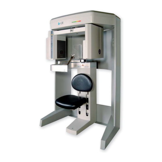
Chapter Introduction System Description The system is a Cone Beam Volumetric Tomography and Panoramic X-ray device used for dental head and neck applications. The system consists of a Scanner and Computer Workstation which is suitable for an in-office environment. This scanning device is an open design that allows Patients to sit upright during a procedure. -
Page 14: Intended Use Of The Device
Physician, these images provide useful diagnostic information. Intended Use of the Device The Imaging Sciences International (ISI) Scanner constructs a three dimensional model from images taken during a rotational X-ray sequence. The scanner is intended to be used whenever a dentist, oral surgeon, or other physician needs 3D information of high contrast objects. -
Page 15: Major System Items
Introduction Major System Items The system is comprised of the following major items: Scanner • Computer Workstation • Operator Control Box with 50 ft. (15.2m) Cable • Patient Emergency Stop Box with 10 ft. (3m) Cable • Interlock Jumper Cable, 8 inch (20cm) •... -
Page 16: Standard Limited Warranty
17-19 Operators’ Manual Standard Limited Warranty Imaging Sciences International (ISI) warrants the original purchaser that this hardware system will be free from defects for a period of one (1) year from the date of delivery. During the warranty period, ISI will correct any defects in material or workmanship, at no charge for materials. -
Page 17: Backup Recommendations
Backup Recommendations The owner/operator is responsible for performing data backup. It is recommended that the following data be backed up regularly: Imaging Sciences International folder (located in • C:\Program Files) Patient data (typically LocalRoot or ImageRoot folder) •... - Page 18 17-19 Operators’ Manual 990400 Rev C 2010 May 1...
-
Page 19: Chapter 2 - Safety Items
Chapter Safety Items Important Safety Information Imaging Sciences designs its products to meet stringent safety standards. However, to maintain the safety of Operators and Patients, you must operate the equipment correctly and properly and ensure the equipment is properly maintained. -
Page 20: Safety Precautions
17-19 Operators’ Manual Advisories are used to defined information for the ADVISORY: operator regarding advice towards use of the device or a process. Notes are used to highlight important or unusual points to be NOTE: brought to the attention of the operator. Safety Precautions WARNING The X-ray device may be dangerous to the Patient and Operator if... -
Page 21: Explosion Hazard
Safety Items WARNING In the event of an electrical fire, only use extinguishers that are labelled for that purpose. Using water or other liquids on an electrical fire can lead to fatal or other serious personal injury. WARNING In the event of an electrical fire, to reduce the risk of electrical shock, try to isolate the equipment from the electric source before attempting to extinguish the fire. -
Page 22: Laser Beam Hazards
17-19 Operators’ Manual Collision System The Gantry motor is programmed to operate at a rotational force of < = 15 lbf (66.7N). Interference or incidental contact with the Gantry during rotation, which results in an interruption in Gantry motion, will be detected and trigger a system stall event. This will result in a system fault condition which will cause the following system events to occur: Stepper Motor power is removed... -
Page 23: Radiation Safety
Safety Items Radiation Safety X-rays are dangerous to both operator and others in the vicinity unless established safe exposure procedures are strictly observed. Use the following safety measures to ensure safety to the Patient and Operator. The useful and scattered beams can produce serious or fatal bodily injuries to Patients and persons in the surrounding area if used by an unskilled operator. -
Page 24: System Safety Devices
17-19 Operators’ Manual System Safety Devices Emergency Stops This manual contains instructions for safe operation of this dental X- ray System. In the event of an emergency (any moving component collides with any parts of the equipment or items in the environment, or that could cause physical injury to the Patient), the Operator and/ or Patient should utilize the Emergency Stop buttons to turn off the power to all moving parts in order for the Patient to be safely... -
Page 25: Sample Site Plan
Safety Items Sample Site Plan Below are two typical scanning room layouts that illustrate the system interconnect for the Warning System, Operator Control Box (Emergency Stop) and Interlock System which are all describe above. Room layouts must provide a means for audio and visual communication between the Operator and Patient. -
Page 26: Interlock And Warning System Schematic
17-19 Operators’ Manual Cable 50 ft. [15.2m] (if used) Patient Emergency Stop Scanner Box with Warning 10 ft. [3m] Cable Light or Alarm (not supplied) Hallway CAT 5 Ethernet Cable 50 ft. (15.2m) Computer Workstation Operator Control Box Interlock Cable with 50 ft. -
Page 27: Cabling Requirements
Safety Items Cabling Requirements System cabling connections must be installed away from walkways and doorways. It is recommended to run cabling along wall perimeters. If there is a chance of mechanical damage due to the cable location, then the use of conduit or other means of protection should be considered. -
Page 28: System Labels
17-19 Operators’ Manual System Labels The following labels are attached to the system. Label Definition and Location Symbol Definition Patient Emergency Stop Panel Label Location: Can either be hung from the chair support EMERGENCY mechanism or held in the Patient’s hand. STOP Indicator Panel Label Location: Front Overhead... - Page 29 Safety Items CAUTION: THIS X-RAY UNIT MAY BE DANGEROUS TO PATIENT AND OPERATOR Turns Unit On UNLESS SAFE EXPOSURE FACTORS AND OPERATING PROCEDURE ARE OBSERVED. UNAUTHORIZED USE IS PROHIBITED. Turns Unit Off Location: Control box Starts the Scan Power Ready X-Ray On Fault Emergency Stop...
- Page 30 17-19 Operators’ Manual CAUTION: LASER RADIATION DO NOT STARE INTO BEAM <1mW 670nm CLASS II LASER PRODUCT General Warning Location: Gantry Laser Patient Alignment Panel Location: X-Ray Source Assembly Laser Seat Height Adjustment Chair Warning Label MAXIMUM LIFTING CAPACITY General Warning <...
- Page 31 Safety Items Chair Installation Label WARNING PINCH POINT Pinch Point KEEP HANDS CLEAR Seat Weighs 6.8 KG (15 LBS) Seat Weight Location: Seat Assembly Gate Label WARNING PINCH POINT General Warning KEEP HANDS CLEAR Location: Chair Gate Pinch Point 990400 Rev C 2010 May 1 2-13...
- Page 32 17-19 Operators’ Manual Rear Overhead Label Modes of Operation: Continuous & Intermittent General Warning Location: Rear Overhead Warning Electrical Hazard Type B (Body) applied part complies with IEC 60601-1 Non-Ionizing Radiation Recycle Chair Cable Control Box Cable Interlock Cable Warning Cable Network Cable to Work Station Computer Cable...
- Page 33 Safety Items Fuse Label Location: Rear Overhead Interlock Fuse X-Ray On Lamp Fuse X-Ray Supply Fuse Fuse X-Ray Power Supply Label MODES OF OPERATION: CONTINUOUS & INTERMITTENT COMPLIES WITH IEC 60601-2-7 AND Continuous : Intermittent IEC 60601-2-28 Location: X-Ray Power Supply 990400 Rev C 2010 May 1 2-15...
- Page 34 17-19 Operators’ Manual Capacitor Warning Label Capacitor Has >300VDC General Warning Wait 5 minutes for capacitor discharge before handling. Location: X-Ray Power Supply Capacitor Caution Label DO NOT USE GROUNDED TEST EQUIPMENT ON THIS UNIT Location: X-Ray Power Supply CE/ETL Label...
- Page 35 Safety Items Serial Label Manufactured By Locations: Tube Head Assembly, X-Ray Power Supply, X-Ray Controller, Beam Limiter, Rear Overhead, Leg Model No. Serial No. Do Not Use with i-CAT SCAN Only Use with i-PAN SCAN Location: i-Pan Head Positioner Push to Release Label Location: i-Pan Head Positioner...
- Page 36 17-19 Operators’ Manual 990400 Rev C 2010 May 1 2-18...
-
Page 37: Chapter 3 - System Controls And Indicators
Chapter System Controls and Indicators Controls and Indicators are found on the following system units: Operator Control Box • Patient Alignment Panel • Patient Emergency Stop Control • System Status Indicators • Operator Control Box ON powers the Scanner and the POWER indicator lights to show that the device is ON. -
Page 38: Patient Emergency Stop Control
17-19 Operators’ Manual Patient Emergency Stop Control PATIENT EMERGENCY STOP allows the Patient to halt all X-ray and scanning activities by pressing the button. The Emergency Stop Control can either be hung from the head support mechanism or held in the Patient’s hand as desired. -
Page 39: Chapter 4 - System Startup And Shutdown
Chapter System Startup and Shutdown System Startup The System includes the Scanner and a Computer Workstation. The system is available for use immediately after System Startup, no device warmup is required. Both units must be ON to function properly. To start the system, do the following: 1. - Page 40 17-19 Operators’ Manual If changes were made to a case study, the following dialog box appears. a. Click Yes. The dialog box closes. b. Click Create New Workup. c. Enter a name for new Workup in the Workup Name: field. Click OK...
-
Page 41: Chapter 5 - Managing Patient Data
Chapter Managing Patient Data Patient Information When Vision is launched, the Patient Information window is displayed. The Study List (shown below) lists all Patients that were entered into the database. The combination of Patient ID, Name, and Birthdate identify a unique patient, and all studies captured with this combination are listed under the same patient. -
Page 42: Study Information
17-19 Operators’ Manual The order in which patients are listed may be altered by clicking a header above the Study List. For example, clicking Birth Date changes the Study List to display numerically by birth dates, starting from month 01 down to 12. Clicking Birth Date again reverses the order, displaying the 12th month first. - Page 43 Managing Patient Data Field Display Description CT Image Raw CT data RAW_CT File Type Digital X-ray (PAN image) Raw PAN data Study is ready to be viewed Creation Date/ Time Study is in the acquisition phase In Progress Study Date- CT study is being reconstructed with the...
-
Page 44: Hide/Display Study List
17-19 Operators’ Manual Hide/Display Study List The Study List can be hidden by selecting Tools > Hide Study List from the Main menu. When hidden, the Study List appears as shown below. To display the Study List, select Tools > Show Study List from the Main menu. -
Page 45: Add New Patient
Managing Patient Data 2. Click Yes to confirm deletion of Patient Dataset, including all scans and workups. A second confirmation dialog is displayed. 3. Click Yes to confirm deletion. Add New Patient To add a new Patient 1. From the Main menu, select File > New Patient or right click an existing image from Patient Study list and select Acquire New Scan. -
Page 46: Edit Patient Details
17-19 Operators’ Manual The Enter Patient Information screen may have additional NOTE: tabs for entering names in Standard (Single Byte), Ideographic, or Phonetic characters. For setup instructions, see DICOM Character Set for New Files 3. Enter Patient data in the corresponding fields as applicable. A unique Patient ID must be added, such as a Patient file •... -
Page 47: Access Patient Data
Managing Patient Data 2. If desired, limit the number of Patients listed by using the check boxes in the Show area at the lower right side of the dialog box. Only Patients whose data matches the selected criteria are displayed. Done - Patient Data entered and scanned •... -
Page 48: Delete A Patient
17-19 Operators’ Manual Delete a Patient To delete an existing Patient: Deleting a Patient does not delete any of the Patient’s scan NOTE: data. 1. From the Main menu, select File > New Patient. 2. Click (highlight) the Patient to delete and click Delete. 3. -
Page 49: Patient Positioning
Chapter Patient Positioning and Protocols Patient Positioning Positioning the patient properly and minimizing patient movement are the keys to optimal scan results. Several system features can be used to assist with patient positioning and are detailed in the following paragraphs. The figure below shows the location of these features and the order in which they are generally used to position a patient. -
Page 50: Patient Chair
17-19 Operators’ Manual Patient Chair Patient Align Buttons Gate Chair Mounting Slots There are two sets of mounting slots for the chair. Use the following table as a guideline for initial placement of the chair: Patient Height Chair Position 4’ 9” and Taller Lower Slots Under 4’... -
Page 51: Gate
Patient Positioning and Protocols Gate The gate swings open to allow Patient seating. The Patient should be seated facing forward with hands in lap. WARNING Closing the Gate creates a pinch point. Keep hands and other body parts clear when closing Gate. Close Gate prior to scanning, making sure the magnet is secured in its locked position. -
Page 52: Head Support And Head Strap
17-19 Operators’ Manual Head Support and Head Strap Head Support Locking Knob Head Support Head Support Adjusting Knob The Head Support slides forward or backward for head stabilization. The Patient’s head should be supported firmly between the Chin Cup and Head Support. Grasp the Adjusting Knob and pull forward or push backward to move the Head Support into the proper position. -
Page 53: Alignment Light
Patient Positioning and Protocols To Use the Head Strap: 1. Attach one end of the Head Strap to one side of the Head Support. 2. Wrap Head Strap around Patient’s forehead and secure to other side of Head Support. For scans that are specific to TMJ or orthodontics, only the head support and head strap should be used. - Page 54 17-19 Operators’ Manual Horizontal light - Position at the Occlusal Plane between the • lips (smile line). Vertical light - Position at 1.5 inches in front of condyles. • Make sure that the turret has enough clearance as to NOT NOTE: brush the Patient’s shoulders as it rotates.
-
Page 55: Instruct Patients Prior To Exam
Patient Positioning and Protocols Instruct Patients Prior to Exam It is important to inform patients of what to expect during a scan so that they are prepared and avoid movement during the scan. Patients should be informed of the following: The turret rotates around the head during the scan. -
Page 56: Protocol Guidelines
17-19 Operators’ Manual Protocol Guidelines Refer to the Acquisitioning chapter for information specific NOTE: to PAN scan positioning and acquisition. In general, protocols should be selected based on the field of view (FOV) required for the study while minimizing radiation dose to the patient. -
Page 57: Chapter 7 - Acquisitioning (Scanning)
Chapter Acquisitioning (Scanning) Volume Scans Once Patient data is entered and the Patient is properly positioned, acquisitioning can begin. Refer to the Patient Positioning and Protocols chapter for NOTE: detailed information about patient positioning. 1. From the Main menu select File > New Patient. 2. - Page 58 17-19 Operators’ Manual 4. Select a Size of Reconstructed Volume from the drop-down list to indicate the Diameter position of the X-ray sensor. 2 arches/anchor, 8.9 seconds, 0.3 Voxel - recommended • when data is exported to implant planning software systems such as Nobel or SimPlant....
-
Page 59: Preview, Dry Run, And Capture Scans
Acquisitioning (Scanning) 5. Select a Resolution from the drop-down list box. In general, the lower the voxel size and the longer the scan time, the better the resolution and detail; however, a smaller voxel size and longer scan time creates a larger data set so the reconstruction time is longer. - Page 60 17-19 Operators’ Manual Operation Guidelines: A site review should have been performed by a qualified • physicist prior to system installation to ensure proper equipment layout for safe operation of the system. If any changes are made to the equipment layout or •...
- Page 61 Acquisitioning (Scanning) the Preview tab. See Viewing and Reconstructing Raw Patient Scans 4. Dry Run is used to give the Patient a demonstrate of the machine motion and also checks shoulder clearance without any radiation exposure. The Dry Run scan rotates the turret in the exact manner that is required for the selected protocol, but does not expose the Patient to any radiation.
-
Page 62: Dose Area Product Feature
17-19 Operators’ Manual 8. The scan is ported to the Vision preview screen for anatomy reconstruction (shown below). Dose Area Product Feature The Dose Area Product (DAP) feature requires a license for activation. Once activated, DAP displays the patient radiation dose measurement for each exposure. - Page 63 Acquisitioning (Scanning) The DAP Summary • dialog displays after a scan is captured and reconstruction begins in VisionQ for both CT and PAN scans. This dialog shows the DAP value for the patient’s full (Primary) scan, the number of Previews, and the Total Study DAP value of all Previews and the...
-
Page 64: Quick Picks
17-19 Operators’ Manual Quick Picks Quick Picks are created and named by the Operator. A Quick Pick captures and saves to memory the following settings: Exposure, Volume Center, Size of Reconstructed Volume, and Resolution. For convenience, speed, and accuracy, the Operator may create Quick Picks of commonly used scan settings. -
Page 65: Pan Scans (Optional)
Acquisitioning (Scanning) PAN Scans (Optional) A PAN scan is a scan mode that creates a Panoramic exposure that is a two dimensional image. Patient positioning is critical for PAN scans. Perform a PAN Phantom test, described in Quality NOTE: Assurance, if image quality is degraded. 1. - Page 66 17-19 Operators’ Manual 5. Insert the Chin Rest and Bite Tip Holder into the Positioning Block. 6. Seat the Patient in the chair with an Erect posture. The neck must be as straight as possible to avoid the spine getting in the view. Close the gate.
- Page 67 Acquisitioning (Scanning) 10. When patient is positioned, close head holder arms so temple pads fit to patient’s temples. If necessary, loosen Head Support Knob and adjust head holder forward or backward as needed to fit head holder to patient. Tighten Head knob Support...
- Page 68 17-19 Operators’ Manual 18. When prompted, press the Scan button on the Control Box. An audible alarm is sounded and the X-ray ON light is illuminated during radiation exposure. 19. Check the Preview to ensure the following: Verify patient is positioned properly at a 10 angle.
- Page 69 Acquisitioning (Scanning) WARNING The X-ray device may be dangerous to the Patient and operator if you do not observe and follow the operating instructions. Do not operate this system unless you have received training to perform a procedure. 21. Click the Capture button to start the scan. The system moves approximately 1/4 rotation to the Home Position and then displays the scan parameters on a dialog.
- Page 70 17-19 Operators’ Manual To Save a PAN Scan as JPEG or TIF: 1. If PAN image is not displayed, click on file type DX in Study List. 2. Right-click on image to display popup menu, then click the desired option to save image as a JPEG or TIF.
-
Page 71: Chapter 8 - Reconstruction Of Anatomy
Chapter Reconstruction of Anatomy Preview Screen Once Patient data is acquired or data for a Patient is loaded, the software immediately reconstructs the Patient anatomy images. (User modified Patient data, referred to as a Workup, can also be loaded to the preview screen. While data loading is occurring, a preview window appears in the center of the screen. - Page 72 17-19 Operators’ Manual Once data is successfully reconstructed, the Preview screen appears as shown below, showing the Panoramic, Sagittal, Coronal, and Axial views of the skull through midline. PATIENT DATABASE PATIENT IMAGES PANORAMIC VIEW PATIENT DETAIL SAGITTAL CORONAL AXIAL VIEW VIEW VIEW VIEW...
-
Page 73: Using Quality Control Frames
Reconstruction of Anatomy Patient Detail View shows detailed Patient data, including acquisition details for the currently selected Patient workup that is highlighted in the Patients in Database list. Panoramic View shows a wide detail view of the selected points on the Axial View. - Page 74 17-19 Operators’ Manual 2. Click Toggle to display the last image of the scan. Toggle as needed to compare first and last frames. Frames should look identical if patient did not move. 3. Click Subtraction. Values for motion factor (Mf) and brightness density (Bd) are displayed.
-
Page 75: Panoramic View (Tru-Pan Feature Set As Default)
Reconstruction of Anatomy Panoramic View (Tru-Pan Feature Set as Default) When the Tru-Pan feature has been enabled on your system, studies are automatically computed and displayed in the Panoramic View. Tru-Pan uses a set of algorithms to automatically construct the Panoramic View and increase image quality. - Page 76 17-19 Operators’ Manual Changing the Panoramic Method You can change the panoramic method used in one of two ways: Click Cancel on the Computing Tru-Pan dialog. • Right-click on the panoramic image to display the pop-up • menu and click Select Panoramic Method. The Panoramic Method dialog is displayed.
- Page 77 Reconstruction of Anatomy The Automatic Arch Detection and Manual Arch Settings NOTE: options are legacy methods for displaying images in the Panoramic View. Automatic Arch Detection - Automatically detects the • Maxilla and Mandible contourlines so that you can manually adjust the Panoramic View. See Manually Adjusting the Panoramic View Manual Arch Settings - Displays the Contourline Setup...
-
Page 78: Manually Adjusting The Panoramic View
17-19 Operators’ Manual The Tru-Pan image does not include the regions below the • bottom of the bony jaw and far above the condyle heads and maxillary sinuses. The purpose is to represent the entire jaw only where dentists are interested. The inclusion height is from the bottom of the bony jaw to a level above the condyle heads. - Page 79 Reconstruction of Anatomy To adjust the Panoramic View: 1. Select whether the Maxilla or Mandible contourline is used as the Panoramic View adjustment reference by clicking on the desired contour line in the Sagittal or Coronal View. The selected contourline is shown as a solid line; the line which is not currently selected is shown as a dotted line.
-
Page 80: Removing Circumference Artifacts
17-19 Operators’ Manual 3. Click check boxes to add desired contourlines. 4. Click OK. The dialog box closes and the selected settings are used for the Sagittal, Coronal, and Axial views. Removing Circumference Artifacts Circumference Artifacts are displayed in the Preview Screen as horizontal lines in the Coronal and Sagittal views and a white partial circle around the Axial View. -
Page 81: Adjusting Mip, Centerline And Image Type
Reconstruction of Anatomy Adjusting MIP, Centerline and Image Type The following slice control bar is found in various views and positions throughout the system software. CENTER-LINE POSITION SLICE THICKNESS MIP/RADIOGRAPH CONTROL TOGGLE CONTROL Center-Line Position - click and drag the Center-Line •... -
Page 82: Adjusting Brightness And Contrast
17-19 Operators’ Manual Adjusting Brightness and Contrast All views include a window level Brightness/Contrast cursor tool. By default, this cursor is displayed. When cursor appears as shown, click and drag up/down and left/ right to adjust brightness and contrast. Brightness - left and right. •... -
Page 83: Zoom Feature
Reconstruction of Anatomy Zoom Feature Most views allow zooming in and out to view more or less detail for the displayed image. To use the zoom feature: 1. Move the cursor to the bottom right of the image where the zoom function is to be used. - Page 84 17-19 Operators’ Manual Setting Filters for a Single Image To change the filter setting for an individual image: 1. Right-click image and select Set Filter > and select filter setting. The selected filter setting is applied. Setting Filters for One or More Image Types To change the filter setting for one or more image types: 1.
-
Page 85: Taking Measurements
Reconstruction of Anatomy Resetting all Filters to the Default Values To reset filters to the default values: 1. From the Main menu, select Tools > Filter Settings > Reset To Default. 2. Click Yes. The dialog box closes and all filter settings are set to the default. - Page 86 17-19 Operators’ Manual 1. To make an HU measurement, right click image and select HU Statistics. The menu closes and the cursor changes to the hu measurement symbol. 2. Click, drag, and click to define an area. Measurement statistics appear in the upper right corner of the image.
- Page 87 Reconstruction of Anatomy To switch off the hu cursor: 1. Right click the image. A popup window appears. 2. Click HU Statistics on the popup menu. The menu closes and the cursor reverts to the default cursor. Measurements can be selectively removed from a view as desired.
-
Page 88: Distance
17-19 Operators’ Manual Distance The system software allows making distance (linear) measurements for all image views. To make a linear (distance) measurement: 1. To make a measurement, right click image and select Distance. The menu closes and the cursor changes to the distance measurement symbol. - Page 89 Reconstruction of Anatomy 3. Repeat steps 2 and 3 to take additional measurements. A maximum of nine distance measurements can be taken at a time in a normal view and four in a cross section view. To switch off the distance cursor: 1.
-
Page 90: Rotating Views
17-19 Operators’ Manual Rotating Views The Volume Rotation feature is disabled on studies that are NOTE: using the Tru-Pan feature. The Sagittal, Coronal and/or Axial views can be rotated. To rotate a view: 1. Hover the cursor over the lower right corner of the desired view. -
Page 91: Saving Views As Jpeg Image Files
Reconstruction of Anatomy Saving Views as JPEG Image Files Data in any view in Vision can be saved as a JPEG image file. To save view as a JPEG Image File: 1. Right click image and select Save as JPEG. The file is named and saved into a customized directory based on the type of image... - Page 92 17-19 Operators’ Manual 2. Then do one of the following: a. Click Create New Workup. b. Enter a name for the new workup in the Workup Name: field. c. Click OK. The dialog box closes and the new workup is displayed on the Select a Workup dialog box.
-
Page 93: Load An Existing Workup
Reconstruction of Anatomy If a workup was made or changed and an attempt is made to close the Vision software or switch to a different Patient, the following dialog box appears. To save the changes made, click Yes. The Select a Workup dialog box appears. -
Page 94: Delete An Existing Workup
17-19 Operators’ Manual Delete an Existing Workup To delete an existing workup: 1. Right-click any image on Preview screen and select Save This Workup. 2. Right-click the Workup to delete. 3. Click Yes. The dialog box closes and the selected Workup is deleted. -
Page 95: Viewing And Reconstructing Raw Patient Scans
Reconstruction of Anatomy Viewing and Reconstructing Raw Patient Scans Raw scan data that is displayed in the Patient Images section can be reconstructed using different volume and resolution parameters, and preview scans can be viewed and manipulated. To Reconstruct Raw Images: 1. - Page 96 17-19 Operators’ Manual 4. If desired, select the Quantum IQ checkbox to apply this reconstruction type when the image is processed. See Quantum for more information on Quantum IQ. 5. Click Reconstruct. The raw DICOM images are reconstructed as specified. To Load Preview Frames: 1.
-
Page 97: Quantum Iq
Reconstruction of Anatomy Quantum IQ Quantum IQ is an image processing option that may be performed on an image volume when it is reconstructed. Quantum IQ smoothes out the noise in the soft tissue areas. Standard Deviation (SD) values in soft tissue (red) decrease with Quantum IQ applied. - Page 98 17-19 Operators’ Manual WARNING Quantum IQ will reconstruct raw data with emphasis on removing noise. This may lead to image data at the boundaries between hard and soft tissue to appear less defined. This tool cannot be a substitute for your professional expertise and judgment. To apply, click the Quantum IQ checkbox to select it.
-
Page 99: Chapter 9 - Detail Screens
Chapter Detail Screens Preview Screen All Detail Screens are accessed by double-clicking a corresponding view on the Preview Screen. To correlate the mouse position on the Preview screen to the Sagittal, Coronal, and Axial views, hold down the C key on keyboard and move the mouse. A yellow mark shows the correlated positions on the other views. -
Page 100: Implant Planning Screen
17-19 Operators’ Manual Coronal View - double-click displays the MPR Screen. • Axial View - double-click displays the TMJ Screen. • Detail screens can also be selected from the Screen menu accessed from the top menu bar. This enables movement from one detail screen to another without having to access the Preview screen. - Page 101 Detail Screens image rotates the 3D image in the direction of the cursor. Double right click-and-hold the mouse button horizontally rotates the image. The mouse scroll wheel is active to scroll through the slices. Cross Section Views (lower right) shows cross section •...
- Page 102 17-19 Operators’ Manual The blue hash mark represents the center line of the axial slices displayed on the cross section views. (The corresponding center cross section slice is displayed with a blue frame in the cross section views.) The orange hash marks represent the other axial slices displayed on the cross section views.
- Page 103 Detail Screens c. Drag the O in the center of the diagonal slice control to adjust the pan focal trough. d. Drag the O in the center of the vertical slice control (right side of view) up or down to change the height of anatomy viewed in the cross section views.
- Page 104 17-19 Operators’ Manual To Use the 3D Model View 1. Right-click in the 3D Model view to display a popup menu. 2. Select desired option to change the view. Show Volume - Displays a full 3D volume model of the •...
-
Page 105: Estimate The Nerve Canal
Detail Screens Estimate the Nerve Canal The Estimate Nerve Canal feature can be used to mark the left, right or both nerve canals, based on your needs. It is important to manipulate the imagery so that you can fully visualize the nerve canals prior to initiating this feature. - Page 106 17-19 Operators’ Manual Prior to Beginning a Nerve Canal Estimate (Tru-Pan Disabled, Manual Adjustment of Contourlines): 1. Set Panoramic Method to Manual Arch Settings, if not already selected. a. On the Preview screen, right-click on an image view and choose Select Panoramic Method. b.
- Page 107 Detail Screens 2. On the axial view, click and drag the blue dots on the contourline as needed to bring the nerve canal(s) into view on the panoramic view. NERVE CANALS ADJUST CONTOURLINE 3. Double-click the panoramic view image to display the Implant Planning screen.
- Page 108 17-19 Operators’ Manual 5. On the axial slice position view, click and drag the blue dots to adjust the contourline to bring the nerve canal(s) into clear focus. When you hover on a dot, a yellow line is displayed on the panoramic map view showing the location you are adjusting.
- Page 109 Detail Screens Estimate Nerve Canal A combination of the axial slice position, panoramic map, NOTE: and cross-section views can be used to mark the nerve canal(s) in any order desired. The following steps describe the recommended workflow. You may choose to use a different workflow to estimate the nerve canal(s).
- Page 110 17-19 Operators’ Manual If a previous nerve canal estimate is detected by the system NOTE: when the Estimate Nerve Canal option is selected, a dialog is displayed: Click Yes to remove current estimation and begin nerve canal estimation from scratch or click No or Cancel to cancel the action. When using the mouse wheel to scroll through slices, you can NOTE: hold down the Shift key or Ctrl key to change the sensitivity of the...
- Page 111 Detail Screens each point. A cross is displayed on both the axial slice position and panoramic map views. ANTERIOR MARKED POINTS At a minimum, you must mark the four foramina to estimate NOTE: both nerve canals (two foramina if only marking the left or right canal).
- Page 112 17-19 Operators’ Manual 6. View and check the marked nerve canal(s) on the cross section view: a. Click and drag the center HORIZONTAL O on the horizontal slice SLICE CONTROL control to display the desired cross section. b. On the cross section view, check that the nerve canal markings are roughly in the center of the cross...
- Page 113 Detail Screens b. Add additional points as needed on the axial slice position and/or panoramic map views. If the estimate is slightly off, you may be able to recalculate it by adding additional points without having to remove points. c. To remove points, click Remove Last Point button. Points are removed in last-created to first-created order.
-
Page 114: Ceph Screen
17-19 Operators’ Manual Remove a Nerve Canal Estimation 1. Right click, select Remove Nerve Canal Estimation and choose one of the three options on the drop-down, depending on the estimation to be removed. 2. On the dialog, click Yes to remove the nerve canal estimate. Ceph Screen Double-clicking the Sagittal View on the Preview Screen displays the Ceph Screen. - Page 115 Detail Screens The Ceph screen displays the Lateral Cephs in Radiographic and MIP mode as well as a Coronal View in MIP mode, all at the thickness of the volume. The last image is a Mid Sagittal Slice at 20mm thick. Right-clicking the blank view at the bottom right of the Ceph screen displays a single item popup menu.
-
Page 116: Mpr Screen
17-19 Operators’ Manual Z Direction Amplitude To remove the airway information from the View, right click the airway view and select Untag Airways. If Tag Airways is reselected after certain image manipulations have occurred, a dialog is displayed. Click OK in the dialog, then in the Mid Sagittal image, click the airway below the flap. - Page 117 Detail Screens The MPR Screen allows scrolling through the Axial (upper left), Sagittal (upper right), and Coronal (lower left) slices. The resulting selections are displayed in the lower right view of the MPR Screen. The mouse scroll wheel is active to scroll through the slices. To use the MPR Screen: 1.
- Page 118 17-19 Operators’ Manual 3. To reposition the line, drag either end point of the line. To view the result of a non-linear (irregular) slice: 1. To view a non-linear slice, right click view and select Irregular. A pointer cursor is displayed. 2.
- Page 119 Detail Screens To explore additional cut planes in an animated (consecutive) fashion: 4. To view additional cut planes, right- click view and select Explore. A pointer cursor is displayed. 5. Drag the center of the circle to position the cut planes slice. 6.
-
Page 120: Tmj Screen
17-19 Operators’ Manual 8. To adjust the playback speed, right-click any image and select Explore Speed 9. Enter desired animation speed in the Movie Playback Speed field. 10. Click OK. TMJ Screen Double-clicking the Axial View on the Preview Screen displays the TMJ Screen. - Page 121 Detail Screens To use the TMJ Screen: 1. If necessary, pan the Axial (SMV) View (upper left) down in the window to see the condyles. (See Pan Feature.) 2. Use the scroll bar center (O) tool to locate the condyles for proper mapping.
- Page 122 17-19 Operators’ Manual 6. Drag the yellow and blue end circles to adjust the angle of each Condyle Map. Green markings indicate the anterior of the Condyle. Red markings indicate the posterior of the Condyle. 7. To create Coronal Slices, click the red circle. To measure: 8.
-
Page 123: Dicom Setup
Chapter Tools DICOM Setup DICOM (Digital Imaging and Communications in Medicine), is an industry standard for digital images which is a means for medical imaging products to share images. DICOM Database and DICOM Export Setup 1. From the top Main menu, select Tools > Setup. 990400 Rev C 2010 May 1 10-1... - Page 124 17-19 Operators’ Manual DICOM Database Root Folder - contains patient data that • is required for creating DICOM images. DICOM Export Destination Folder – this path selection • determines where the DICOM images are to reside when executing the procedure. Export DICOM 2.
-
Page 125: Pacs
Tools 3. The rescan progress is displayed at the top of the Study List. Add Rotated Volume The Add rotated volume as a new study when exported checkbox is used to export a rotated volume study as a new study. See Export for more information. - Page 126 17-19 Operators’ Manual 2. For Unicode, you can select to enter names in one or more entry options: Standard (Single Byte), Ideographic, and Phonetic. For Latin Alphabet, Standard (Single Byte) is the only available entry option. These selections determine the tabs that are available for data entry of names on the Enter Patient Information window (see Add New Patient 3.
-
Page 127: Check Read/Write Access To Image Database
Tools be displayed in Vision, select Ideographic in the Person’s Name Display Priority window, and click Increase to move it to the top of the list. If you later want to view the Phonetic name, set Phonetic to the highest priority. Latin Alphabet names will always appear as single byte entries, even if Standard (Single Byte) is set as the lowest priority. -
Page 128: Export Dicom
17-19 Operators’ Manual Export DICOM Export DICOM enables both original CT and PAN (DX) studies and rotated CT studies to be exported. Files are placed in the DICOM Export Destination Folder specified on the Setup dialog, from where they can be placed on a network or other media. Export an Original CT or PAN study 1. -
Page 129: Export A Rotated Ct Study
Tools Export a Rotated CT study A rotated study is a study with volume rotation applied. After a study is rotated, the Export DICOM >Rotated Study option becomes active. When this option is selected, a rotated study is exported to the specified DICOM Export Destination Folder. -
Page 130: Create Export Cd
17-19 Operators’ Manual 2. From the Main menu, select Tools > Export DICOM. 3. Select Multi-File DICOM and Uncompressed options. 4. Ensure Destination is set to C:\DICOM Exports. If not, browse to this location. 5. Click OK. Wait for study to uncompress. 6. - Page 131 Tools To create a DICOM CD: 1. From the top Main menu, select Tools > Create Export CD. Patient Patient Studies Checkbox 2. Select desired Output Selections. Single File DICOM - one large image file (recommended) • Multi-File DICOM - a separate file for each image slice, •...
-
Page 132: Erase Cd-Rw
17-19 Operators’ Manual Erase CD-RW This Erase CD option can only be used if using re-writable CDs. 1. From the top Main menu, select Tools > Create Export CD. The CD Burner window is displayed (shown above). 2. Click Erase CD-RW. 3. -
Page 133: Import Study
Tools Import Study CAUTION CAUTION To add patient studies to the database, follow the procedure below. Do not use Windows Explorer to copy studies to the database. Manually copying a study to the database using a method other than the one described below will require a potentially time-consuming rescan operation. -
Page 134: Reporting
17-19 Operators’ Manual Reporting Patient reports are generated by inserting patient images into a single or multiple page document. Patient information and text notes can also be inserted as required. Once these reports are created and saved, they are readily available for printing and distribution. Patient reports can also be accessed for editing. -
Page 135: Create New Report
Tools Create New Report To create a new Patient Report: 1. Click (highlight) a patient from the Study List. Allow time for the Patient Image to load. 2. From the Main menu, select Tools > Create Report. 3. Click Create New Report from the box. Insert Image into Patient Report: 4. - Page 136 17-19 Operators’ Manual When adding a Panoramic image to a report from the NOTE: Implant Planning screen, (Panoramic selected for Single Images), be aware that a slice location indicator scale is displayed at the bottom of the image. Each tick on this scale represents the location of a slice.
- Page 137 Tools 6. Images can be repositioned or sized by clicking the image and then holding down left mouse button and dragging the cursor. Cross Arrows – used to move image • Double Headed Arrow – used to size image • Insert Text Box: 7.
- Page 138 17-19 Operators’ Manual Add Page 12. Select Insert > Page from the Main menu or right-click a report page and select Add Page. The new page appends to the end of the report. 13. To change the page properties, select File > Page Setup from the Main menu or right-click the page and select Page Properties.
-
Page 139: Modify Existing Report
Tools Modify Existing Report This function is used to edit reports that were previously created. 1. From the Main menu, select Tools > Create Report. 2. Click Modify Existing Report from the box. 3. The Load Preview box is displayed. Select the Patient Report to modify and click Load. - Page 140 17-19 Operators’ Manual 990400 Rev C 2010 May 1 10-18...
-
Page 141: Chapter 11 - Calibration
Chapter Calibration The Panel, Collimators, and Geometry Calibrations can be conducted by the Owner / Operator of the device. It is recommended that the Panel Calibration be performed once a week. Panel Calibration The Panel Calibration is performed for both Portrait and Landscape positions. - Page 142 17-19 Operators’ Manual The Calibration screen is displayed. 3. Click the Calibrate button (top) in the Panel field. WARNING The X-ray device may be dangerous to the Patient and operator if you do not observe and follow the operating instructions. Do not operate this system unless you have received training to perform a procedure.
-
Page 143: Collimators Calibration
Calibration Collimators Calibration It is recommended to perform the Collimators Calibration once a week to ensure optimal image quality. This calibration is also necessary if a mechanical adjustment is made to the Beam Limiter or if image quality has degraded. The Collimator Calibration runs in both Portrait and Landscape positions and takes less than 3 minutes to complete. -
Page 144: Geometry Calibration
17-19 Operators’ Manual 10. On the Control Box, press Scan when prompted. An audible alarm is sounded and the X-ray ON light is illuminated during radiation exposure. 11. The scan starts in the Landscape and continues into the Portrait mode, displaying three screen shots in both modes. - Page 145 Calibration 15. Align the BB Phantom crosshair slits with the laser cross beams. For an accurate alignment, the laser beams should penetrate though the phantom crosshair slits and appear on the receptor panel. 16. Click the Preview button which is located at the bottom of the Calibration screen.
- Page 146 17-19 Operators’ Manual To reposition the phantom right or left on the Preview screen, use the Back / Front feature. 21. When the BB Phantom is centered and level, click the Calibrate button on the Geometry panel (bottom). 22. Select both the Landscape and Portrait calibration modes. WARNING The X-ray device may be dangerous to the Patient and operator if you do not observe and follow the operating instructions.
- Page 147 Calibration 25. The calibration starts with the Landscape Scan. PORTRAIT SCAN LANDSCAPE SCAN Metal Platform Support (below FOV) Ensure that the metal platform support is below the Field of NOTE: View (as shown above.) 26. At the start of the scan, red circles are displayed around each BB. At this point, check data (above green progress bar), to ensure the following is displayed: Beads detected = 24, Beads valid = 24...
- Page 148 17-19 Operators’ Manual 990400 Rev C 2010 May 1 11-8...
-
Page 149: Chapter 12 - Quality Assurance
Chapter Quality Assurance QA Phantom Test The following Quality Assurance Tests can be conducted by the Owner / Operator of the device. It is recommended that the System Quality Assurance be performed annually or if image quality becomes degraded. For this purpose, the following procedures are provided with a QA Phantom Test and QA Water Test. - Page 150 17-19 Operators’ Manual 4. Center the QA Phantom on the platform with the Air Hole positioned at the left rear of the Gantry (shown below). AIR HOLE ACRYLIC LDPE TEFLON If the Tru-Pan feature is enabled on your system, you may NOTE: want to change the default panoramic method to Manual Arch Settings or None before beginning acquisition of phantom images.
- Page 151 Quality Assurance 9. Click Preview to check the phantom position. WARNING The X-ray device may be dangerous to the Patient and operator if you do not observe and follow the operating instructions. Do not operate this system unless you have received training to perform a procedure.
-
Page 152: Line Pair Evaluation
17-19 Operators’ Manual 17. The following preview screen is displayed. Line Pair Evaluation 18. Access the QA Test images for evaluation by double clicking Coronal View (bottom image, 2 from the right). 19. The image below is displayed. In the upper right corner view, slide the Vertical and Horizontal lines to the Line Pairs centers as shown below. -
Page 153: Distance Measurement Test
Quality Assurance 20. Zoom Line Pair image (upper left). To zoom, start at the upper right corner of image and hold down left mouse button and drag cursor across the image. 21. Right click the image and select Set Filter > Hard. 22. -
Page 154: Hounsfield Unit (Hu) Measurements
17-19 Operators’ Manual 24. Right click view and select Distance. 25. Drag the Distance cursor to draw a line from the outside line of set 16 to the outside line of set 10, as shown above. 26. The measurement (displayed in upper corner of image) should be between 41 and 42 mm. - Page 155 Quality Assurance 30. In the upper right corner view of the Coronal View, slide the Vertical and Horizontal lines to the centers as shown below. 31. Zoom the Axial image (upper left). To zoom, start at the lower right corner of the image and hold down left mouse button and drag cursor across the image.
- Page 156 17-19 Operators’ Manual c. Move the position of the slice to the middle of the phantom as shown in the figure. 32. Right click the image and select HU Statistics from the menu (also, right click to turn off HU Statistics). 33.
-
Page 157: Qa Water Phantom Test
Quality Assurance QA Water Phantom Test The Water Phantom Test is a noise level and uniformity test. The HU measurements are taken at five different regions within the Water volume. It is important that the Water Phantom provided is used for these tests. 1. - Page 158 17-19 Operators’ Manual Size of Reconstruction Volume: Diameter 16cm - Height 13cm Resolution: .4 voxel, 8.9 Seconds Quantum IQ: NOT selected WARNING The X-ray device may be dangerous to the Patient and operator if you do not observe and follow the operating instructions. Do not operate this system unless you have received training to perform a procedure.
- Page 159 Quality Assurance 13. Press the Scan button on the Control Box when prompted. An audible alarm is sounded and the X-ray ON light is illuminated during radiation exposure. 14. Select Cancel at the Contourline Setup prompt, if displayed. 15. Access the HU measurement image for evaluation by double clicking Coronal View (bottom image, 2 from the right).
-
Page 160: Noise Level Test
17-19 Operators’ Manual Noise Level Test 17. Zoom the Axial image (upper left). To zoom, start at the lower right corner of the image and drag the cursor across the image. 18. At the bottom of the top-right image scale, click and hold the ●... -
Page 161: Uniformity Test
Quality Assurance Uniformity Test 21. Use the Noise Level Test dataset (previous procedure), if not available, perform steps 1 to 13. If using the Noise Level Test, right click the HU data (upper right corner of image) and select Remove all measurements. 22. -
Page 162: Pan Phantom Test
17-19 Operators’ Manual 23. Note and record the Mean and SD values of the four regions. See chart below. 24. After recording values, a fifth ROI is required from the center of the water area. The fifth measurement replaces the first measurement, since four measurements are the limit. - Page 163 Quality Assurance Lasers are available while the Volume tab is selected (not PAN). PHANTOM LASER LINE BITE TIP PHANTOM PLATFORM BITE TIP HOLDER 5. Start test by selecting File > New Patient from the Main menu or right click an existing image from database and select Acquire New Scan.
- Page 164 17-19 Operators’ Manual 10. The system moves approximately 1/4 rotation to the Home Position and then displays the scan parameters. 11. Click OK to start the scan process. 12. Press Scan button on Control Box. An audible alarm is sounded and the X-ray ON light is illuminated during radiation exposure.
-
Page 165: Radiation Output Test
Quality Assurance 15. The image above is an example of a system properly aligned for PAN scanning. All but two of the metal balls are circular in shape. Poor Image Quality 16. The image above is an example of a system that is not properly aligned for PAN scanning. -
Page 166: Measured Dose
17-19 Operators’ Manual Measured Dose The table below shows measurements performed on the detector for a landscape mode standard scan. Tube Potential (kV) Selected Scan Time (seconds) Number of Frames Approximate Exposure Time (seconds) Displayed mAs 18.54 Measured Exposure at Detector (mR) Measured Exposure at Detector / mAs (mR/mAs) 10.14 Measured Exposure at 1m (mR/mAs) -
Page 167: Chapter 13 - Radiation Environment Survey
Chapter Radiation Environment Survey The direct and scattered beams can produce serious bodily injuries to Patients and persons in the surrounding area. Adequate precautions must always be taken to avoid or reduce exposure to the useful beam, as well as scattered radiation. Refer to the following figure and related table to determine scattered beam measurements. -
Page 168: Conditions Of Operation - 8.9 And 26.9 Second Scans
17-19 Operators’ Manual Conditions of Operation – 8.9 and 26.9 Second Scans All data was acquired using Radcal Model 9010 Radiation monitor, with 10X5-180 chamber. The data was acquired in concentric circles of radii listed in table below A Phantom Laboratories head phantom was placed within the beam to act as the scattering agent. -
Page 169: Diameter 16Cm 8.9 Second Scan
Radiation Environment Survey Diameter 16cm 8.9 Second Scan Distance in Feet Exposure Exposure scans/wk scans/wk scans/wk Exposure Location [meter] (mR) (R) mR/wk mR/wk mR/wk mR/mAs 3 [0.91m] 0.33 332.1 0.018 16.6 6 [1.82m] 0.09 86.7 0.005 9 [2.74m] 0.04 40.4 0.002 3 [0.91m] 0.35... -
Page 170: Scatter Measurements For 26.9 Second Scan
17-19 Operators’ Manual Scatter Measurements for 26.9 Second Scan 26.9 second scan using pulsed X-ray: 619 frames, 12 ms pulse width at 5 mA taken in Diameter16cm scanning mode. Based on this, the Estimated workload is: 10 scans per week yielding a workload of 6.2 mA-min/week 25 scans per week yielding a workload of 15.5 mA-min/week 50 scans per week yielding a workload of 61.0 mA-min/week Diameter 16cm 26.9 Second Scan... -
Page 171: Conditions Of Operation - Pan Scans
Radiation Environment Survey Conditions of Operation – PAN Scans All data were acquired using 2 Technical Associates Mark V integrating ion chamber meters. Measurements were made in concentric circles of radii listed in the tables below. An AAPM head phantom was placed in the beam to act as a scattering agent. The center of the ion chamber was placed at the same height as the center of the beam. -
Page 172: Scatter Measurements For 20 Second Pan Scan, Large 2X2
17-19 Operators’ Manual Scatter Measurements for 20 Second PAN Scan, Large 2x2 Distance in Feet Exposure Exposure scans/wk scans/wk scans/wk Exposure Location [meter] (mR) (R) mR/wk mR/wk mR/wk mR/mAs 3 [0.91m] 0.115 115.0 1.15 1.15 2.88 5.75 6 [1.82m] 0.033 33.0 0.33 0.33... -
Page 173: Scan Times And Settings
Radiation Environment Survey Scan Times and Settings Voxel Size # of Acquisition (mm) Frames Times 0.4 / 0.3 37.10 17.8 Scans 0.4 / 0.3 18.54 0.25 / 0.2 / 0.125 37.07 26.9 0.4 / 0.3 10.11 Half Scan 0.25 / 0.2 / 0.125 20.27 14.7 PAN Large... -
Page 174: Dose And Imaging Performance Information
17-19 Operators’ Manual Dose and Imaging Performance Information The Computer Tomography Dose Index (CTDI) was measured using a 10cm, 3cc, pencil ionization chamber from Radcal Corporation (10X9-3CT) in conjunction with a Radcal Corporation 16cm diameter cylindrical CT head phantom (20CT6). This phantom has one hole at the center and four more at 90°... -
Page 175: Dose Profile
Radiation Environment Survey Diameter Diameter 16 cm 23 cm 6 cm 6 cm 13 cm 11 cm 10 cm 8 cm maxilla mandible 4 cm 17 cm Acq. Time CTDI CTDI CTDI CTDI CTDI CTDI CTDI CTDI CTDI CTDI CTDI CTDI CTDI CTDI... - Page 176 17-19 Operators’ Manual Vertical Dose Profile for Standard 8.9s Scans Diameter 16cm Diameter 23cm Position cm µ Dose/Scan Position Diameter Diameter 16cm 23cm 990400 Rev C 2010 May 1 13-10...
-
Page 177: Sensitivity Profile
Radiation Environment Survey Sensitivity Profile A 40 µm diameter Tungsten wire was scanned using the standard Diameter 16cm protocol with 0.2mm voxel resolution. The wire was held vertically at the system isocenter. The Hounsfield units of the reconstructed image of the wire was measured at several slice positions with 0.2mm width and the resulting profile was compared against a Gaussian curve. -
Page 178: Drywall Attenuation
17-19 Operators’ Manual Sensitivity Profile Position Z-Axis mm Drywall Attenuation The attenuation due to typical drywall found in offices was measured. A simulated wall was constructed from two sheets of 5/8- inch thick gypsum wallboard, spaced 4 inches apart, mounted on a wood frame. -
Page 179: Recommended Operating Requirements
Radiation Environment Survey Recommended Operating Requirements Local agencies or government bodies or international standards may dictate requirements for installation of the system in order to protect personnel and the public from exposure from the radiological output of the device. Consult your local agencies, government bodies, or international standards for actual requirements which apply. -
Page 180: X-Ray Tube Assembly
The system shall be registered with the local agency or • government body. X-ray Tube Assembly Imaging Sciences International utilizes the SXR 130-15-0.5 X-ray Tube from Superior X-Ray Tube Company to manufacture the X- ray head assemblies. Nominal X-Ray Tube Voltage 120 kV Max. - Page 181 Radiation Environment Survey Operator Data Available focal spot size (mm): Available target angle: 15° Anode construction: Vacuum cast copper with tungsten target Cathode construction: Vacuum tube nickel with TO RECEPTOR tungsten filament Max. Tube operating voltage: 130 kVp Full wave rectified Inherent filtration/Window material: 2.0 mm/Glass...
- Page 182 17-19 Operators’ Manual X-Ray Power Supply Tube Head Assembly Tested (no other additional accessories tested) 6 Pin Red Connector 1000-0 X-Ray Power Supply 1536 X-Ray Power 35-0 Tube Head 1535 Tube Head Cable Supply Cable 120V 10A supplied from a 3 Pin Orange secondary of the Connector...
- Page 183 Radiation Environment Survey EMISSION CHARACTERISTICS (Full Wave Rectified, Single Phase, Bi-polar) 70 kVp 100 kVp 90 kVp 130 kVp TUBE CURRENT (mA) FILAMENT VOLT/AMPS CHARACTERISTICS: 60 Hz AC & DC ANODE HEATING/COOLING CURVE ANODE HEAT STORAGE CAP 30,000 H.U. MAX. ANODE HEATING & COOLING RATE 165 HU PER SECOND * OIL SUBMERGED ONLY...
- Page 184 17-19 Operators’ Manual X-Ray Tube Head Heating and Cooling Chart HEATING COOLING TIME (min.) CONDITIONS FOR X-RAY TUBE HEAD HEATING AND COOLING TEST MACHINE CYCLED IN PAN MODE: 1 SCAN EVERY 5 MINUTES PAN MODE SETTINGS: 94KV 5MA 20SEC SCAN AMBIENT TEMPERATURE: 22 990400 Rev C 2010 May 1 13-18...
-
Page 185: Chapter 14 - Product Information
Chapter Product Information Technical Specifications X-ray Source Tube Voltage: 120 kVp(eff) Tube Current: 3-7 mA Voltage Wave Shape: Constant Potential Focal Spot: 0.0197 inches (0.5 mm) Duty Cycle: Source to Sensor distance: 28.1 inches (71.4 cm) Source to Patient distance*:19.5 inches (49.53 cm) (center of rotation) * The patient must be properly positioned in the Head Support Positioner Mechanism for each patient for all applications in order to have the focal spot to skin distance as large as possible. -
Page 186: Power Requirements
17-19 Operators’ Manual Image Detector: Amorphous Silicon Flat Panel (readable area), 9.37” width x 7.56” height (23.8 cm width x 19.2 cm height) Sensor Front Panel Attenuation Value: Less than 1mm of aluminum equivalent (information for reference only) Gray Scale: 14 bit Voxel Size: 0.4/0.3/0.25/0.2 mm Image Acquisition: Single 360 degree rotation (maximum) Scan Time: 26.9/8.9 seconds... -
Page 187: Apparent Resistance Of Supply Mains
Product Information Apparent Resistance of Supply Mains For the purpose of obtaining the apparent resistance of supply mains, resistance is determined according to the following formula: U0 - U1 Where: U0 is the no-load Mains Voltage U1 is the Mains Voltage under load. I1 is the Mains Current under load. -
Page 188: Environmental Specifications
17-19 Operators’ Manual Environmental Specifications Operating 50 to 95 degrees Fahrenheit (10 to 35 degrees Celsius) 10% to 90% Relative Humidity, non-condensing Transportation and Storage -4 to 158 degrees Fahrenheit (-20 to 70 degrees Celsius) 10% to 90% Relative Humidity, non-condensing Acquisition Computer Acquisition Computer requires a Dedicated Line and a Surge Protector is recommended. -
Page 189: Extension Cords
Product Information Extension Cords Do not use any extension cords which are not provided with the system. Be aware that multiple portable socket outlets or extension cords are not to be connected to the system. External Item Do not connect any items or equipment to this system which are not part of the system. - Page 190 17-19 Operators’ Manual Test Name Test Level/ Results / Immunity Equipment Class Notes Performance Criteria Met Emissions Testing Radiated Emissions Class A; Group 1 Compliant Conducted Voltage Emissions Class A; Group 1 Compliant IEC61000-3-2 Harmonic Class A Compliant Current Emissions IEC61000-3-3 Voltage Class A Compliant...
-
Page 191: Equipment Standards
Product Information Equipment Standards The System was tested and/or evaluated against and found compliant to the following standards/requirements: UL 60601-1 IEC 60601-2-28 CSA C22.2 No. 601.1 EN 980 JIS Z4701 EN/ISO 13485 JIS Z4703 IEC/EN 60601-2-32 JIS T0601 IEC/EN 60825-1 IEC/EN 60601-1 CE-MDD 93/42/EEC IEC/EN 60601-1-1... -
Page 192: Preventive Maintenance Schedule - For Owner / User
17-19 Operators’ Manual Preventive Maintenance Schedule - for Owner / User Daily: Routine Dusting - all surfaces Monthly: Clean all surfaces and check for failed/faulty indicator lights. Yearly: Check for satisfactory image quality. IT IS THE RESPONSIBILITY OF THE USER TO INSURE THAT THE EQUIPMENT IS MAINTAINED IN COMPLIANCE WITH THE MANUFACTURER'S RECOMMENDED MAINTENANCE SCHEDULE. -
Page 193: Cleaning
Product Information Cleaning Cleaning the equipment frequently, especially if corroding chemicals are present is a function of the Operator. Unless otherwise instructed, use a cloth moistened with warm water and mild soap. Do not use strong cleaners and solvents as these may damage the finish. Be careful when cleaning to avoid liquid leaking inside the Gantry. -
Page 194: Replaceable Parts
17-19 Operators’ Manual Check Laser Alignments Check Centerline Alignment (using Chair Center Locator) Check Crosshair Laser (align with notches on Receptor Panel Cover) Inspect Tube Housing Components Certification Label Warning and Indicators Oil Leaks Physical Damage Mounting System Stability Inspect Beam Limiting Device Physical Damage Certification Label Check/Inspect X-Ray Controller... -
Page 195: Supplemental Components
Product Information Supplemental Components Patient E-stop Carbon Fiber Head Rest Part # 1304-0 Part # 27-0 Quantity 1 Quantity 1 Glide Head Restraint Band Part # 1000179 Part # 27-1 Quantity 4 Quantity 50 Tool Kit Velcro Head Restraint Part # 5-0 Part # 903-0 Quantity 1 Quantity 1... -
Page 196: Optional Pan Scan Accessories
17-19 Operators’ Manual Chair Center Locator Platform Assembly Part # 26-16 Part # 14-4-0 Quantity 1 Quantity 1 Operators’ Manual Part # 990400 Quantity 1 Optional PAN Scan Accessories Bite Tip Holder PAN Head Holder Part # 980220 Part # 33-0 Quantity 2 Quantity 1 Position Alignment... -
Page 197: System Gantry Dimensions
Product Information System Gantry Dimensions TOP VIEW FRONT VIEW 990400 Rev C 2010 May 1 14-13... - Page 198 17-19 Operators’ Manual 990400 Rev C 2010 May 1 14-14...
-
Page 199: Chapter 15 - Networking Support Setup
Chapter Networking Support Setup Networking Support Overview Networking support within VisionQ and standalone Vision creates a convenient mechanism for sharing image data within an office or clinic. Using network storage provided and maintained by the customer, system software monitors the connection and allows scanning to proceed even if the network is temporarily broken. -
Page 200: Network Support Installation/Setup
17-19 Operators’ Manual If the Study List database update process cannot be performed by the computer that has been designated by the system to be the master, slave computers will receive the following message at the top of the Study List: “Study List updates blocked by the computer named...”. Investigate the problem with the identified master computer. -
Page 201: Install Sweeper Service
Networking Support Setup Install Sweeper Service 1. Double-click the SweeperSetup icon in the Program Files\Imaging Sciences International\iCAT Software folder to execute the program. A setup wizard is displayed. 2. Click Next on all wizard screens to install the Sweeper service. -
Page 202: Migrate From Standalone To Server
17-19 Operators’ Manual Migrate from Standalone to Server NOTE: Perform this procedure only if upgrading or migrating from • an existing standalone setup. If the existing network setup shares a portion of the local • disk of the VisionQ computer, it is still considered standalone and this procedure should be followed. -
Page 203: Change Image Root Folder
Networking Support Setup 4. If a folder named bak is present in the Image Root Folder, the proj0000.raw files in it, as well as the bak folder itself, can be deleted. 5. Check that the folder C:\LocalRoot does not exist. If it does exist, check if it is empty. -
Page 204: Sweeper Controller
The Sweeper controller provides the user interface to the Sweeper service and is accessed by clicking the Sweeper icon in the system tray. If the controller screen is accidently closed, click Start > All Programs >Imaging Sciences >SweeperController.exe to restore. Stop Sweeper Pause Sweeper... -
Page 205: No Network Access At Startup
Networking Support Setup No Network Access at Startup When VisionQ or standalone Vision is first launched, it tests whether the Image Root Folder is accessible on the network. If it is not, the No Network Access dialog is displayed. Use fallback operations if desired. -
Page 206: Network Fails During Operations
17-19 Operators’ Manual Network Fails During Operations If a network failure occurs during use of VisionQ or standalone Vision, the following occurs: The Study List goes blank (since it comes from the server • which is no longer accessible). Error messages are displayed in the Sweeper log file. •... -
Page 207: Chapter 16 - Remote System Import And Export
Chapter Remote System Import and Export Remote System Import and Export Overview The VisionQ Remote Service application enables the import of patient demographic details and sends the DICOM datasets generated after a scan to a PACS server. The Remote Service also allows querying and retrieving of desired datasets to a Vision workstation, which can be viewed with the Vision Standalone application. -
Page 208: Import Installation And Setup
17-19 Operators’ Manual (2) Request issued (3) Request received VisionQ PDI Service Class User (4) Patient data sent Remote (5) Response received Server (1) “Process” command issued Import Installation and Setup If the PDI.dll has not been installed, place the PDI.dll in the same folder where the VisionQ.exe resides. - Page 209 Remote System Import and Export 3. Click Import. The Patient Importer screen is displayed. 4. Click Config. 5. Enter Station name, IP Address, AE Title, and Port number for the remote server from where files are to be imported. 6. Click Save, and then Close. 7.
-
Page 210: Set Up Practice Management Interface
17-19 Operators’ Manual The Options button on the Patient Importer window enables NOTE: setting of the date format and the AE title for the local Acquisition computer, and enables auto process. These settings are optional and do not have to be changed. Set Up Practice Management Interface 1. -
Page 211: Import Patient Data
Remote System Import and Export Import Patient Data 1. From the VisionQ Main menu, select File > New Patient. 2. Click Import. 3. On the Patient Importer screen, click Process. Patient data is retrieved from the remote system and listed at the bottom of the screen. -
Page 212: Remote System Export (Rssm)
17-19 Operators’ Manual Remote System Export (RSSM) VisionQ enables DICOM images to be transferred from the VisionQ to a remote system, such as a Picture Archive and Communications System (PACS). The Remote Service Send Module (RSSM) enables the transfer using DICOM storage protocol (C-STORE). RSSM continuously monitors the local folder that is setup to receive the images to be exported. - Page 213 Remote System Import and Export 3. Click Options. 4. Click Browse in Source image folder section and browse to the folder where the DICOM files are to be placed for export. Create a new folder if desired. Do NOT use the current image root or local root folder.
- Page 214 17-19 Operators’ Manual 6. In On failure section, select the amount of time (in seconds) to wait after a send operation fails before trying again. Also, enter the number of times to retry a failed send operation. The status of a send operation is displayed in the Study List under the PACS heading.
- Page 215 Remote System Import and Export Select Use Existing Connection to use the same connection • for sending a Storage Commitment request and receiving a Storage Commitment response from the PACS server. - or - Select New Connection to receive Storage Commitment •...
-
Page 216: Rssm Logs
17-19 Operators’ Manual RSSM Logs While RSSM is transferring data to the remote system, an icon is displayed in the system tray. Right-click the icon to display a popup menu. The RSSM logs can be accessed by selecting the option for the desired log or by selecting Show. The Show option displays the DICOM Send Module with the following options: The buttons that are active on the DICOM Send Module... - Page 217 Remote System Import and Export 2. A dialog is displayed and the dataset is transferred. 3. If a previous export session has not been successfully transferred, a warning is displayed. 4. Check the RSSM log to determine status of the last transmitted file.
-
Page 218: Rsqm
17-19 Operators’ Manual RSQM The Remote Service Query/Retrieve Module (RSQM) enables CT or iPAN (DX) images to be requested and retrieved from a remote system, such as a Picture Archive and Communications System (PACS) using DICOM service protocols (C-FIND and C-MOVE). The retrieved images can then be viewed and manipulated in the Vision Standalone application. - Page 219 Remote System Import and Export 2. Double-click RSQM.exe. The DICOM Query/Retrieve Module is displayed. 3. Click Options. 4. Click Browse, and browse to the Image Root folder to select it as the default storage location on the local computer. 5. In DICOM section, enter Receiving Port, Receiving IP Address, and Local AE Title.
- Page 220 17-19 Operators’ Manual 6. In Select Allowable Transfer Syntax(es) for Retrieving Datasets section, select transfer syntax to be accepted by RSQM for retrieving datasets from a PACS. Usually the transfer syntax selected for sending datasets to a PACS should be selected for retrieval as well.
-
Page 221: Query And Retrieve Images
Remote System Import and Export Query and Retrieve Images 1. Double-click RSQM.exe. The DICOM Query/Retrieve Module is displayed. 2. Click Config. a. Enter Station name, IP Address, AE Title, and Port number for the DICOM node, such as a PACS, from where studies are to be queried and retrieved. -
Page 222: Status Messages
17-19 Operators’ Manual 4. To retrieve images for a study: a. Select a study from the list. b. Click Retrieve. The images for the selected study are retrieved from the remote server and copied to the local computer in the folder that was specified during setup, usually ImageRoot. - Page 223 Remote System Import and Export Cannot use wildcard character with accession number A wildcard character is not allowed to be used for querying an accession number. Begin the retrieval process... A study is about to be retrieved. Unable to start retrieval. Please check network configuration Cannot initiate the DICOM receiver module.
- Page 224 17-19 Operators’ Manual 990400 Rev C 2010 May 1 16-18...
-
Page 225: Appendix A - Icatvision & Icattransfer
Appendix iCATVision & iCATTransfer iCATVision standalone is used to view images that have been ® acquired by an iCAT Acquisition Computer. We are pleased to ® provide iCATVision free of charge to anyone with access to iCAT scans with no limit on usage and the number of copies. 990400 Rev C 2010 May 1... -
Page 226: Workstation Minimum Requirements
17-19 Operators’ Manual Workstation Minimum Requirements Pentium 3 Intel Core Duo 2.4 GHz or better • 2 GB of RAM minimum, 4 GB preferred • ATI Radeon HD 4650 or nVidia Geforce 9800 GT chip • minimum or ATI Radeon HD 5770 GPU (no integrated Intel GPUs, must be a dedicated GPU) Windows XP Professional, Vista, Windows 7 Professional or •... -
Page 227: Install Icatvision
iCATVision & iCATTransfer ® File structure on iCAT Acquisition Computer: It is not recommended to have the Watch folder located on a NOTE: server because it would slow down the Network speed. 3. On the server or central storage location, create another folder named iCATVision. -
Page 228: Icatvision Setup
17-19 Operators’ Manual iCATVision Setup Refer to for additional DICOM Character Set for New Files NOTE: DICOM setup options. 1. From iCAT Vision select Tools > Setup. 2. Under DICOM Database Root Folder, browse to the iCAT Vision\ iCAT Vision Root and click OK. (This may be on the C: drive or on a networked drive). -
Page 229: Install Icattransfer
Passcode When iCATTransfer is first launched, it opens to the iCATTransfer Validation Screen (below). Instructions are displayed to send an e- mail to Imaging Sciences at keys@imagingsciences.com with your customer information and the authentication code shown on screen. -
Page 230: Icattransfer Setup
17-19 Operators’ Manual iCATTransfer Setup The program must be configured to “watch” for exported DICOM ® data from iCAT in order to authenticate and transfer it to the image root directory. The program needs to be running in the background in order to detect the exportation of the DICOM Data. -
Page 231: Accessing I-Cat Dicom Data
iCATVision & iCATTransfer 3. Under Image Root Folder (Primary Destination), Browse to iCATVision Root folder and select. (This is most likely on a server/central storage location). 4. Click Start. This saves the preset Watch and Root destinations. If START is not clicked the transfer program will not work. NOTE: Remember, iCATTransfer must be running in order for the data to transfer (iCATTranfer can be minimized). - Page 232 17-19 Operators’ Manual 990400 Rev C 2010 May 1...
-
Page 233: Appendix B - Three Dimensional Volume Rendering (3Dvr)
Appendix Three Dimensional Volume Rendering (3DVR) Open Database 3DVR is a standalone program which runs independently and is not part of Vision. 1. To open 3DVR, double click the 3DVR icon. The Program Main menu is displayed. 990400 Rev C 2010 May 1... -
Page 234: Axial Functions
17-19 Operators’ Manual To get started, an image dataset must be loaded. The case MUST be in DICOM format. If importing a case from Vision, make sure to export the case in DICOM3-Multi File format. 2. Click Open Dataset, a browse window is displayed. -
Page 235: W/L (Window/Level
Three Dimensional Volume Rendering (3DVR) W/L (Window/Level) W/L is a tool to adjust Grayscales (Brightness / Contrast). To adjust Brightness/Contrast: 1. Click W/L Radio button. 2. Drag cursor Left/Right to adjust Contrast and Up/Down for Brightness. The W/L values are displayed at the top of screen. ROI (Region of Interest) ROI is a tool used for determining Hounsfield Units. -
Page 236: Distance
17-19 Operators’ Manual Distance The distance tool measures linear distance. To activate Distance tool: 1. Click Distance radio button. 2. Drag cursor from point to point to create a measurement line (see below in green). Linear measurement is displayed in millimeters (upper left corner.) Identify The Identify tool identifies areas of interest at different densities. - Page 237 Three Dimensional Volume Rendering (3DVR) 2. Drag cursor on 3D image to rotate. Patient Chin Cup Display the slice range of interest: 3. On the Axial screen, drag the cursor either UP or DOWN to scroll through the axial slices. Dragging the cursor upward scrolls towards the top of the skull and ragging downward scrolls towards the bottom of the skull.
-
Page 238: Remove Object
17-19 Operators’ Manual Remove Object To remove a piece of anatomy from image: 1. Click the Remove Object box to enable (checkmark). 2. Then click the object of interest highlighted in blue. 3. Close 3DVR Setup window by Chin Cup clicking X (upper right corner of Removed window). - Page 239 Three Dimensional Volume Rendering (3DVR) 4. Drag the cursor in the area between the dental arch, making sure not to include any teeth or bone. This displays the Hounsfield data. The MEAN value is the data of interest in this calculation. It reads a value (most likely a negative value).
-
Page 240: View Volume
17-19 Operators’ Manual View Volume View Volume allows viewing all 3 projections of the 3D data: Axial, Coronal and Sagittal. Also enables the creation of 3D Renderings. Enable View Volume Tools, click the View Volume button. 990400 Rev C 2010 May 1... -
Page 241: Projection Type
Three Dimensional Volume Rendering (3DVR) Projection Type Projection Type enables viewing 3D data in 2 different projections or modes: Radiographic and MIP. Radiographic mode - The above example has • Radiographic mode enabled. The Axial, Coronal, and Sagittal views are all in Radiographic mode. Window/Level can be adjusted in each of the 3 views by NOTE: dragging the cursor in each window. -
Page 242: Volume Edit
17-19 Operators’ Manual Volume Edit Volume Editing is used to select an area of interest to create a 3D rendering. The two methods used are Box and Freehand. Box - with this option, each of the 3 views are displayed •... -
Page 243: Vr Functions
Three Dimensional Volume Rendering (3DVR) VR Functions VR Functions (Volume Rendering) is a tool used for selecting the type of 3D image to create. To Create a 3D Image: 1. From the first View drop-down menu select a direction to display. The choices are: AP (Anterior Posterior) •... - Page 244 17-19 Operators’ Manual Remember that the 3D data is calculated using the boxed NOTE: or freehand selected areas of interest in the Axial, Coronal & Sagittal views. In this sample, the entire volume data is selected in all 3 views. Below is a sample of a 3D image calculated from the selected volume area seen below.
- Page 245 Three Dimensional Volume Rendering (3DVR) Sample of View Types Skin Bone/Teeth Bone Sinus/Bone Transparent Skin Each View Type has its own Parameters, which can be viewed by clicking the VRT Params button. The 3Dimage can be rotated, enlarged or changed to another direction or type.
-
Page 246: Pop Up Menu
17-19 Operators’ Manual Rotate 3D Image To Rotate the 3D image, both the Pan and Zoom functions must be disabled (unchecked). Drag the cursor on the 3D image in the desired rotation direction. Pop Up Menu Pop Up Menu contains the same VR Functions and also some additional functions. -
Page 247: View Full Screen
Three Dimensional Volume Rendering (3DVR) View Full Screen Full Screen displays the 3D image on the entire computer screen. All the same manipulation functions and 3D options are used in this display. Right click to display Pop Up menu to utilize functions. To return to the original viewing format, press <Esc>... - Page 248 17-19 Operators’ Manual 990400 Rev C 2010 May 1 B-16...
-
Page 249: Appendix C - Quick Reference
Quick Reference Navigating the Interface REMINDER Images are displayed as if you are This guide shows how to: looking at the patient from the front. • View reconstructed images • Use main features and tools to optimize an image TO DISPLAY PATIENT IMAGE Click Patient Name. -
Page 250: Suggestions For Adjusting Panoramic Map
17-19 Operators’ Manual Suggestions for Adjusting Panoramic Map Start adjusting the Panoramic map from the Preview Screen. It is recommended to center the anterior point at midline and then move the next two points up closer to the anterior point on each side. Place them a few teeth away from anterior center. -
Page 251: Implant Planning Screen
Quick Reference Guide Implant Planning Screen REMINDER Implant Screen is acquired by double clicking Panoramic View from Preview window or selecting it from the Screen menu. DISPLAYED VIEWS AXIAL SLICE POSITION PANORAMIC MAP 3D MODEL CROSS SECTIONS Center Slice is outlined in Blue. Slice Location Number Slice Location numbers start at “0”... -
Page 252: Panoramic Map
17-19 Operators’ Manual Panoramic Map PAN TOOLS Horizontal Tool Bar Drag the center control button of tool left to right to move the slice location of the Cross Sections. The center slice is outlined in Blue on the Cross Sections. ... -
Page 253: Ceph Screen
Quick Reference Guide Ceph Screen REMINDER Ceph Screen is acquired by double clicking Sagittal View from Preview window or selecting it from the Screen menu. DISPLAYED VIEWS The Ceph Screen displays the Lateral Cephs in Radiographic and MIP mode as well as a Coronal View and a Mid Sagittal Slice (15mm thick). -
Page 254: Install Case Studies From Cds
17-19 Operators’ Manual TMJ Planning Screen REMINDER TMJ Planning Screen is acquired by double clicking Axial View from Preview window or selecting it from the Screen menu. DISPLAYED VIEWS TMJ Screen enables condyle mapping and creating corresponding coronal slice views. CURSOR TOOLS All views have Brightness/Contrast, Zoom and Pan. -
Page 255: Appendix D - System Labels
Appendix System Labels English Symbol Descriptions Locations Symbol Descriptions Locations Emergency Stop Patient Emergency Maximum Lifting Chair Assembly Stop, Control Box Capacity General Warning Control Box, X-Ray X-Ray On Control Box, Front Source, Gantry, Overhead Chair Assembly, Rear Overhead, X-Ray On Lamp Rear Overhead... - Page 256 17-19 Operators’ Manual Symbol Descriptions Locations Symbol Descriptions Locations Breaker Switch On/ Rear Overhead Interlock Fuse Rear Overhead Output for Interlock Rear Overhead X-Ray Supply Fuse Rear Overhead AC In Rear Overhead Fuse Rear Overhead Manufactured For Continuous: Rear Overhead, X- ...
-
Page 257: Français
System Labels Français Symbole Descriptions Emplacement Symbol Descriptions Emplacement chaiseArrêt d’arrêt d’urgence capacité maximale chaise d’urgence pour le patient, de levage boîtier de commande avertissement boîtier de rayons X activés boîtier de général commande, source commande, de rayons X, ensemble supérieur ... - Page 258 17-19 Operators’ Manual Symbole Descriptions Emplacement Symbol Descriptions Emplacement réglage de la panneau Câble réseau vers ensemble supérieur hauteur du siège d’alignement du câble d’ordinateurde arrière patient poste de travail disjoncteur marche/ ensemble supérieur fusible ensemble supérieur arrêt arrière d’interverrouillage arrière sortie pour ensemble supérieur...
-
Page 259: Deutsch
System Labels Deutsch Symbol Beschreibung Standort Symbol Beschreibung Standort Notausschalter Patienten Maximale Stuhl-Bauteil Notausschalter, Hebekapazitat Steuereinheit Allgemeine Steuereinheit, Röntgen ein Steuereinheit, Warnung Röntgenquelle, Vorderseite Gantry, Stuhl- Overhead-Einheit Bauteil, Rückseite Overhead-Einheit, Sicherung Lampe Rückseite Stuhlschranke, Röntgen ein Overhead-Einheit Röntgenstrahlen- Stromversorgung... - Page 260 17-19 Operators’ Manual Symbol Beschreibung Standort Symbol Beschreibung Standort Ausgang für Rückseite Sicherung Röntgen- Rückseite Verriegelung Overhead-Einheit Versorgung Overhead-Einheit Eingangsspannung Rückseite Sicherung Rückseite Overhead-Einheit Overhead-Einheit Hergestellt für Kontinuierlich: Rückseite Röhrenkopfbaugruppe, Röntgenstrahlen- Intermittierend Overhead-Einheit, Stromversorgung, Hergestellt von Röntgenstrahlen- Röntgen-Steuereinheit, Stromversorgung Strahlenbegrenzer, Modell-Nr....
-
Page 261: Italiano
System Labels Italiano Simbolo Descrizione Località Simbolo Descrizione Località Arresto di arresto di Capacità massima di gruppo poltrona emergenza emergenza, quadro sollevamento comandi Attenzione generale quadro comandi, Raggi X attivati quadro comandi, sorgente di raggi X, parte anteriore del ... - Page 262 17-19 Operators’ Manual Simbolo Descrizione Località Simbolo Descrizione Località Interruttore On/Off parte posteriore del Fusibile interblocco parte posteriore del (acceso/spento) gruppo sopraelevato gruppo sopraelevato Uscita per parte posteriore del Fusibile erogazione parte posteriore del interblocco gruppo sopraelevato raggi X gruppo sopraelevato Ingresso CA parte posteriore del Fusibile...
-
Page 263: Polski
System Labels Polski Symbol Opis Położenie Symbol Opis Położenie Wyłącznik awaryjny awaryjnego Maksymalna Fotel wyłącznika nośność pacjenta, Panel sterujący Ogólne ostrzeżenie Panel sterujący, Aparat rtg włączony Panel sterujący, Z Aparat rtg, Gantry, przodu u góry Fotel, Z tyłu u góry, Brama fotela, Bezpiecznik Z tyłu u góry... - Page 264 17-19 Operators’ Manual Symbol Opis Położenie Symbol Opis Położenie Wyjście dla blokady Z tyłu u góry Bezpiecznik Z tyłu u góry zasilania aparatu rtg Gniazdo zasilania Z tyłu u góry Bezpiecznik Z tyłu u góry Wyprodukowanych Tryby działania: Z tyłu u góry, dla...
-
Page 265: Portuguê
System Labels Portuguê Símbolo Descrição Local Símbolo Descrição Local Parada de Parada de Capacidade de Unidade da cadeira emergência emergência do elevação máxima paciente, Painel de controle Aviso geral Painel de controle, Raio X ligado Painel de controle, Fonte de raios X, Painel frontal ... - Page 266 17-19 Operators’ Manual Símbolo Descrição Local Símbolo Descrição Local Liga/desliga Painel superior Fusível de bloqueio Painel superior disjuntor traseiro traseiro Saída para cabo de Painel superior Fusível de fonte de Painel superior bloqueio traseiro raios X traseiro Entrada de CA Painel superior Fusível Painel superior...
-
Page 267: Español
System Labels Español Descripción Ubicaciones Descripción Ubicaciones Símbolo Símbolo Parada de urgencia Parada de urgencia Capacidad máxima Montaje de la silla del paciente, de elevación Cuadro de control Advertencia general Cuadro de control, Rayos X activados Cuadro de control, Fuente de rayos X, Parte superior ... - Page 268 17-19 Operators’ Manual Descripción Ubicaciones Descripción Ubicaciones Símbolo Símbolo Interruptor de Parte superior Cable de bloqueo Parte superior encendido y posterior posterior apagado Salida de bloqueo Parte superior Fusible de la fuente Parte superior posterior de alimentación de posterior rayos X Entrada de CA Parte superior Fusible...
-
Page 269: Svenska
System Labels Svenska Symbol Platser Symbol Platser Beskrivning Beskrivning Nödstopp Nödstoppspanel för Max. lyftkapacitet Stolenhet patient, Kontrollbox Allmän varning Kontrollbox, Röntgen PÅ Kontrollbox, Röntgenstrålkälla, Ovandelens Ställning, Stolenhet, Lampsäkring för framsida Ovandelens baksida, Röntgen PÅ Stolgrind, Ovandelens baksida Röntgenströmförsör jning Laser Röntgenstrålkälla,... - Page 270 17-19 Operators’ Manual Symbol Platser Symbol Platser Beskrivning Beskrivning Utgång för Ovandelens baksida Röntgen- Ovandelens baksida förregling tillförselsäkring Växelström in Ovandelens baksida Säkring Ovandelens baksida Tillverkad för Rörets huvudenhet, Kontinuerligt: Ovandelens baksida, röntgenströmförsörj Intermittent Röntgenströmförsör Tillverkad av ningen, jning ...
-
Page 271: 简体中文 (Chinese
System Labels 简体中文 (Chinese) 符号 描述 位置 符号 描述 位置 紧急停止 病人紧急停止、控 最大承重量 椅装置 制箱 常规警告 控制箱、 X 射线 X 射线开 控制箱、前顶架 源、台架、椅装 置、背顶架、椅挡 X 射线开指示灯 背顶架 板、 X 射线电源 保险丝 激光 X 射线源、台架、 夹点 椅装置、椅挡板 病人校准面板 电源 控制箱、前顶架 电力危险警告 背顶架... - Page 272 17-19 Operators’ Manual 符号 描述 位置 符号 描述 位置 交流输入 背顶架 保险丝 背顶架 客户 管头装置、 X 射线 持续:间断 背顶架、 X 射线 电源、 X 射线控制 电源 制造商 器、限束器、背顶 架及支脚 型号 序列号 腿 标签 位置 紧急停止 病人紧急停止 注意:使用此 X 射线装置时,必须遵守安全曝光因数与操作程序,否则可能会对 控制箱 病人与操作员造成危害。 未经授权严禁使用。 注意:激光辐射,请勿直视射线...
-
Page 273: 繁體中文 (Taiwan
System Labels 繁體中文 (Taiwan) 符號 描述 位置 符號 描述 位置 緊急停止 病患緊急停止、 最大起重量 椅裝配 控制箱 X 光開 一般警告 控制箱、X 光源、 控制箱、前頂架 台架、椅裝置、 背頂架、 背頂架 椅擋板以及 X 光 X 光開指示燈 電源 保險絲 X 光源、台架、病 雷射 夾點 椅裝置、椅擋板 患校準面板 電源 控制箱、前頂架 電力危險警告 背頂架... - Page 274 17-19 Operators’ Manual 符號 描述 位置 符號 描述 位置 製造商為 管頭裝配、X 光電 持續:間斷 背頂架、X 光 源、X 光控制器、 電源 由製造 限束器、背頂架及 支腳 型號 序號 標籤 位置 緊急停止 病患緊急停止 注意:使用此 X 光裝置時,必須遵守安全曝光因數與操作程序,否則可能會對病患 控制箱 與操作員造成危害。 未經授權嚴禁使用。 X 光源 注意:雷射輻射,請勿直視光 <1mW 635nm II 類雷射產品 注意:雷射輻射,請勿直視光...
-
Page 275: 한국어 (Korean
System Labels 한국어 (Korean) 기호 설명 위치 기호 설명 위치 환자 비상 정지 , 제 비상 정지 최대 하중 능력 의자 조립체 어 상자 제어 상자 , X- 선 X- 선 켜짐 제어 상자 , 앞쪽 머 일반 경고 광원 , 갠트리 , 의 리... - Page 276 17-19 Operators’ Manual 기호 설명 위치 기호 설명 위치 AC 입력 뒤쪽 머리 위 퓨즈 뒤쪽 머리 위 튜브 헤드 조립체 , 연속 : 간헐 뒤쪽 머리 위 , X- 제조 의뢰사 X- 선 전원 공급기 , 선 전원 공급기 X- 선...
-
Page 277: 日本語 (Japanese
System Labels 日本語 (Japanese) シンボル 説明 場所 シンボル 説明 場所 緊急停止 患者緊急停止、コント 最大リフト能力 チェアアッセンブリ ロールボックス 一般警告 コントロールボック X 線オン コントロールボック ス、X 線照射源、ガン ス、前部オーバー トリー、チェアアッセ ヘッド ンブリ、後部オーバー X 線オンランプ ヘッド、チェアゲー ヒューズ 後部オーバーヘッド ト、X 線電源装置 レーザー X 線照射源、ガント ピンチポイント シートアッセンブリ、... - Page 278 17-19 Operators’ Manual シンボル 説明 場所 シンボル 説明 場所 AC イン 後部オーバーヘッド ヒューズ 後部オーバーヘッド 販売元 チューブヘッドアッセ 継続 断続 後部オーバーヘッド、 ンブリ、X 線電源装置、 X 線電源装置 製造元 X 線コントローラ、 ビームリミッタ、後部 モデル番号 オーバーヘッド、レッ グ シリアル番号 ラベル 場所 緊急停止 患者緊急停止 注意 この X 線ユニットは、安全照射要項や操作安全手順に従わない場合、患者や コントロールボックス...
-
Page 279: Česky
System Labels Česky Symbol Popis Umístění Symbol Popis Umístění Nouzové zastavení Nouzový vypínač Maximální nosnost Blok sedačky pacienta, ovládací skříňka Všeobecné varování Ovládací skříň, RTG RTG spuštěn Ovládací skříňka, zdroj, otočný portál, čelní část horního blok sedačky, zadní modulu... - Page 280 17-19 Operators’ Manual Symbol Popis Umístění Symbol Popis Umístění Výstup pro pojistku Na zadní straně Pojistka napájení Na zadní straně dveří horního modulu rentgenu horního modulu Vstup síť. napájení Na zadní straně Pojistka Na zadní straně horního modulu horního modulu Výrobce...
-
Page 281: Nederlands
System Labels Nederlands Symbool Beschrijvingen Locaties Symbool Beschrijvingen Locaties Noodstop Noodstop voor patiënt, Maximaal Stoel bedieningseenheid hefvermogen Algemene Bedieningseenheid, Zekering voor lampje Bedieningseenheid, waarschuwing röntgenbron, portaal, Overhead voor stoel, overhead achter, stoelpoort, Zekering voor lampje Overhead achter röntgenvoedingstoevoer "Röntgenstraling AAN"... - Page 282 17-19 Operators’ Manual Symbool Beschrijvingen Locaties Symbool Beschrijvingen Locaties Output voor overheadgedeelte Zekering overheadgedeelte beveiliging achter röntgenvoeding achter Wisselstroom in overheadgedeelte Zekering overheadgedeelte achter achter Vervaardigd voor Röntgenkop, Continu : Overhead achter, röntgenvoeding, intermitterend röntgenvoeding Vervaardigd door röntgenbediening, straalbegrenzer, Modelnummer...
-
Page 283: Русский Язык
System Labels Русский язык Знак Описание Расположение Знак Описание Расположение Экстренная Экстренная Максимальная Узел кресла остановка остановка грузоподъемность пациента, пульт Общее Блок управления, Предохранитель Блок управления, предупреждение источник лампы передняя панель рентгеновского верхнего узла излучения, гентри, узел кресла, задняя Предохранитель... - Page 284 17-19 Operators’ Manual Знак Описание Расположение Знак Описание Расположение Включает Блок управления Предупреждение о Задняя панель питание блока кабеле верхнего узла Выключает питание блока Запускает сканер Регулировка Панель Сетевой кабель к Задняя панель высоты кресла регулировки рабочей станции верхнего узла положения...
- Page 285 System Labels Этикетка Расположение Экстренная остановка Экстренная остановка пациента Предостережение: если не следить за факторами безопасного экспонирования и не Блок управления соблюдать процедуру эксплуатации, то эта рентгеновская установка может представлять опасность для пациента и оператора. Использование без разрешения не допускается. Предостережение: лазерное...
-
Page 286: Român
17-19 Operators’ Manual Român Simbol Descriere Locaţii Simbol Descriere Locaţii Oprire de urgenţă Oprire de urgenţă Capacitate maximă Ansamblu scaun pentru pacient, de ridicare Caseta de control Avertizare generală Caseta de control, Raze X pornite Caseta de control, sursă raze X, cadru, parte frontală... - Page 287 System Labels Simbol Descriere Locaţii Simbol Descriere Locaţii Ieşire blocare la Parte posterioară Siguranţă sursă raze Parte posterioară distanţă dispozitiv suspendat dispozitiv suspendat Intrare curent Parte posterioară Siguranţă Parte posterioară alternativ dispozitiv suspendat dispozitiv suspendat Produs pentru Ansamblu cap tub, Continuu: Parte posterioară...
-
Page 288: Türkçe
17-19 Operators’ Manual Türkçe Sembol Tanımlar Konumlar Sembol Tanımlar Konumlar Acil Durdurma Hasta Acil Maksimum Sandalye Aksamı Durdurma, Kaldırma Kapasitesi Kumanda Kutusu Genel Uyarı Kumanda Kutusu, X-Işını Açık Kumanda Kutusu, X-Işını Kaynağı, Ön Ana Cihaz Gantri, Sandalye Aksamı, Arka Ana X-Işınının Açık Arka Ana Cihaz... - Page 289 System Labels Sembol Tanımlar Konumlar Sembol Tanımlar Konumlar Bağlantı Çıkışı Arka Ana Cihaz X-Işını Kaynağı Arka Ana Cihaz Sigortası AC Girişi Arka Ana Cihaz Sigorta Arka Ana Cihaz Kimin için Boru Kafası Sürekli: Aralıklı Arka Ana Cihaz, X- Üretildiği Aksamı, X- Işını Işını...
- Page 290 17-19 Operators’ Manual 990400 Rev C 2010 May 1 D-36...
- Page 292 Kaltenbach & Voigt GmbH Imaging Sciences International LLC Bismarckring 39 1910 North Penn Road D-88400 Biberach, Germany Hatfield, PA 19440 USA Tel: +49 7351 56 0 Tel: 1-215-997-5666 Fax: +49 7351 56 1488 Fax: 1-215-997-5665 e-mail: info@kavo.de 990400 Rev C 2010 May 1...
Need help?
Do you have a question about the i-Cat 17-19 and is the answer not in the manual?
Questions and answers