Table of Contents
Advertisement
Quick Links
INSTALLATION, OPERATION
MODEL:
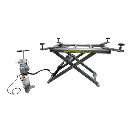
SL-6600
6,600 LB CAPACITY SCISSOR LIFT
FOLLOW THIS MANUAL CAREFULLY TO ENSURE THE EQUIPMENT WILL
FUNCTION CORRECTLY AND PROVIDE MANY YEARS OF DEPENDABLE SERVICE.
FAILURE TO FOLLOW THESE INSTRUCTIONS AND SAFETY WARNINGS MAY
RESULT IN PERSONAL INJURY OR PROPERTY DAMAGE. KEEP THIS MANUAL IN A
SAFE DRY PLACE FOR FUTURE REFERENCE.
& MAINTENANCE MANUAL
®
Advertisement
Table of Contents

Related Manuals for Titan Lifts SL-6600

Summary of Contents for Titan Lifts SL-6600
- Page 1 ® INSTALLATION, OPERATION & MAINTENANCE MANUAL MODEL: SL-6600 6,600 LB CAPACITY SCISSOR LIFT FOLLOW THIS MANUAL CAREFULLY TO ENSURE THE EQUIPMENT WILL FUNCTION CORRECTLY AND PROVIDE MANY YEARS OF DEPENDABLE SERVICE. FAILURE TO FOLLOW THESE INSTRUCTIONS AND SAFETY WARNINGS MAY RESULT IN PERSONAL INJURY OR PROPERTY DAMAGE.
- Page 2 Claims must be filed to cover cost. If you have any questions or if we can be of any further assistance, please don’t hesitate to contact a Titan Lifts® representative at 1-888-908-4826. Thank you for the opportunity to continue to serve your lift equipment needs.
-
Page 3: Table Of Contents
CONTENTS 1-SAFETY ........................1 1.1 INTRODUCTION........................1 1.2 SAFETY INSTRUCTIONS FOR COMMISSIONING ..............1 1.3 SAFETY INSTRUCTIONS FOR OPERATION ................1 1.4 SAFETY INSTRUCTIONS FOR MAINTENANCE ................. 3 1.5 RISKS ............................3 2-UNPACKING & SETUP ....................4 2.1 DELIVERY AND CHECK OF PACKAGES ..................4 3-SPECIFICATIONS ......................5 4-FLOOR REQUIREMENTS ....................6 4.1 SELECTING THE SITE AREA ..................... -
Page 4: 1-Safety
INSTRUCTIONS 1-SAFETY 1.1 INTRODUCTION WARNING: READ ENTIRE MANUAL AND COMPLY WITH ALL SAFETY AND SERVICE PRECAUTIONS. DEATH, PERSONAL INJURY AND / OR PROPERTY DAMAGE MAY OCCUR IF INSTRUCTIONS ARE NOT FOLLOWED CAREFULLY. Personal injury and property damage incurred due to non-compliance with these safety instructions are not covered by the product liability regulations. - Page 5 • Maintain a safe working environment. The work area should be clean, dry, clutter free, and sufficiently lit. • Vehicle doors should be closed during the raising and lowering cycles. • Closely watch the vehicle and lift during the raising and lowering cycles. •...
-
Page 6: Safety Instructions For Maintenance
1.4 SAFETY INSTRUCTIONS FOR MAINTENANCE • Maintenance or repair work should be done by authorized service personnel only. • Work on the electrical equipment should be done by certified licensed electricians only. • Ensure that ecologically harmful substances are disposed of in accordance with the appropriate regulations. -
Page 7: 2-Unpacking & Setup
2-UNPACKING & SETUP Only skilled personnel who are familiar with the lift and this manual shall be allowed to carry out, lifting, handling, transport and unpacking operations. 2.1 DELIVERY AND CHECK OF PACKAGES When the lift is delivered, carefully unpack the lift making sure all the parts have been included. -
Page 8: 3-Specifications
3-SPECIFICATIONS 61” 56” 86 ¾” SPECIFICATIONS SL-6600 Load capacity 6,600 lb Raising / Lowering time 45sec Minimum height 5-13/16” Maximum lifting height 53-3/4” Operating temperature 41-131°F Net weight 980 lb Length 82-3/4” Width Min/Max 39-1/2” / 78 3/4” 110V-120V,60Hz, Power supply... -
Page 9: 4-Floor Requirements
IMPORTANT: SPECIFICATIONS ARE SUBJECT TO CHANGE WITHOUT NOTICE. 4-FLOOR REQUIREMENTS These notes are for your guidance prior to installation. 4.1 SELECTING THE SITE AREA Make sure that adequate space and height is available. 4.2 FLOOR REQUIREMENTS Do not use the lift on any asphalt surface. Make sure the lift is used on a dry, oil/grease free, flat level CONCRETE surface capable of supporting the weight of the lift, the vehicle being lifted, and any additional tools and equipment. -
Page 10: 5-Installation Instructions
5-INSTALLATION INSTRUCTIONS IMPORTANT: THE HYDRAULIC HOSES HAVE BEEN PRE-INSTALLED FOR YOUR CONVENIENCE. BE CAREFUL NOT TO CUT THE HYDRAULIC HOSES DURING THE INSTALLATION PROCESS. 5.1 MOUNT HYDRAULIC POWER UNIT/CONNECT HOSE ASSEMBLY 1. Attach the tow handle(1) to the pedestal(6) using the four(4) supplied attached bolts, washers, and nuts (Fig. -
Page 11: Electrical Connections
5.4 ELECTRICAL CONNECTIONS WARNING: ALL WIRING CHANGES MUST BE PERFORMED BY A CERTIFIED LICENSED ELECTRICIAN. THE STANDARD ELECTRIC MOTOR USED ON YOUR LIFT REQUIRES A 110-120 VOLT, 60HZ, SINGLE PHASE HOOK-UP. WARNING: DO NOT PERFORM ANY MAINTENANCE OR INSTALLATION OF ANY COMPONENTS WITHOUT FIRST ENSURING THAT ELECTRICAL POWER HAS BEEN DISCONNECTED AT THE SOURCE OR PANEL AND CANNOT BE REENERGIZED UNTIL ALL MAINTENANCE AND/OR INSTALLATION PROCEDURES ARE COMPLETED. -
Page 12: Safety Lock Control
6.2.2 SAFETY LOCK CONTROL Press and hold the lowering handle (Fig.3) until the safety lock is engaged the safety lock bar. Fig. 3 6.2.3 LOWERING CONTROL Press the Up button enough to make the safety lock disengage the safety lock bar, squeeze the lock-release handle (Fig. 4), and then press the lowering handle (Fig.3) until the lift is completely lowered. - Page 13 6. Once the rubber saddles have been positioned under the vehicle lifting points, operate the power switch to make contact and lift the vehicle slightly. Test to make sure the vehicle is well balanced and the contact between the rubber saddles and vehicle lifting points are secure by performing the “BUMPER TEST.”...
-
Page 14: 7-Maintenance
7-MAINTENANCE WARNING: DISCONNECT THE POWER BEFORE SERVICING THE LIFT. IMPORTANT: THE MAINTENANCE INTERVALS INDICATED BELOW APPLY TO AVERAGE WORKSHOP USE. THE LIFT SHOULD BE INSPECTED MORE FREQUENTLY FOR SEVERE USE APPLICATIONS. 7.1 MAINTENANCE SCHEDULE It is important to keep the lift clean, dry, and well maintained by establishing a periodic preventive maintenance program to ensure trouble-free operation and long service life. -
Page 15: Maintenance By Operator
7.2 MAINTENANCE BY OPERATOR All moving parts have been lubricated at the factory and should be re-lubricated before the first use and at least once every six months to prevent damage. 7.2.1 HYDRAULIC SYSTEM (FIG. 5) 1. Check the fluid level with the lift fully lowered and add fluid as required. -
Page 16: Operation And Wear Checks
7.2.3 OPERATION AND WEAR CHECKS 1. Examine lift for structural cracks, bends, or other signs of damage prior to each use. Do not use this product if worn or damaged. 7.2.4 LIFT STABILITY 1. Every six months check the nuts of all bolts for correct installation torque. 2. -
Page 17: 8-Troubleshooting
8-TROUBLESHOOTING PROBLEM CAUSES REMEDY The wire connection is loose. Check and make a good connection. Motor does not run and will not raise The motor is burnt Replace it. The motor runs reversely. Check the wire conenction. Overflow valve is loose or jammed. Clean or adjust it. -
Page 18: 9-Diagrams
9-DIAGRAMS FIG. 1 - ELECTRICAL DIAGRAM Pos. Code Name Specification 320201082 Motor 110V-2.2KW-1PH-60HZ-4P 320901014 AC Contactor CJX2-1210/AC110 320401013 PUSH button AR22F0R-11-W 321204021 Protector for AC motor NS2-32... - Page 19 FIG. 2 - HYDAULIC DIAGRAM 1 1. Oil tank 9. Single way valve 2. Oil sucking filter 10. Manual unloading valve 3. Gear pump 11. Flow control valve 4. Coupling 12. Oil tank cover 5. Motor 13. Hose connector (with single way 6.
- Page 20 FIG. 3 - HYDRAULIC DIAGRAM 2 Pos. Code Name Specification 610033301 Power Unit 110V-2.2KW-1PH-60HZ 624001064 Rubber oil hose L-3500mm 615033012 Cylinder 2 TS6600-A05-B01 310101010 Straight connector G1/4--G1/4 624001847 Rubber oil hose L=200mm 615006003 Three way connector 6214E-A4-B4(6214A-A5-B2) 310101010 Straight connector G1/4--G1/4 615033013 Cylinder 2...
- Page 21 FIG. 4 - POWER UNIT DIAGRAM Pos. Code Name Specification 330405014 Oil tank 330101004 Hydraulic block YF-2 330304001 Overflow valve EYF-C 330302001 Single way valve DYF-C 330305002 Throttle valve TC-VF 207103019 Composite washer 330301001 Cushion valve HZYF-C1 202109064 Screw M6*30 330201003B Gear pump (for 1PH motor) CBK-F210...
- Page 22 FIG. 5 - EXPLODED DIAGRAM Pos. Code Name Specification 614033004 Welded arm A TS6600-A01-B01 614033005 Welded arm B TS6600-A01-B02 410330161 Pin shaft of the main arm TS6600-A01-B03 410330171 Up rolling wheel TS6600-A01-B04 410330151 Pin shaft TS6600-A01-B05 410330121 Down shaft of oil cylinder TS6600-A01-B06 410330191 Shaft of the down wheel...
- Page 23 Pos. Code Name Specification 410330573 Low Pad Mount TS6600-A03-B06-C01 612033002 Mechanical safety lock TS6600-A04-B01 614033010 Mechanical lock cover TS6600-A04-B02 614033011 Release pin shaft TS6600-A04-B03 410330761 Safety block TS6600-A04-B05 615033012 Oil cylinder A TS6600-A05-B01 615033013 Oil cylinder B TS6600-A05-B02 208101015 Hose clip D16 16-JB-ZQ-4492 205101008 Bearing...
- Page 24 FIG. 6 - POWER UNIT DIAGRAM Pos. Code Name Specification 614033001B Support bracket TS6600-A06-B01 614033002 Handle TS6600-A06-B02 420330060 Nylon wheel TS6600_M90X43 610033301 Power unit 110V-2.2KW-1PH-60HZ 204301004 Circlip D15_GB894_1 420480080 Handle sheath D22X100 204201004 Spring washer D8_GB_T93 204101005 Flat washer D8_GB_T97_1 615048003 Handle M12X100...
- Page 25 NOTES...
- Page 26 Titan Elite model lifts have been discontinued but still qualify under the same terms as shown above. Titan SL-6600 Scissor Lifts and PREMIER Series 2 Post Lifts are backed by a 2-year replacement parts warranty and a 5-year structural warranty from the date of purchase, to the original purchaser only. The 2-year replacement parts warranty covers power units, hydraulic cylinders, and all other assembly components such as, but not limited to: valves, switches, capacitors etc.
- Page 27 WARRANTY REGISTRATION In order to utilize the warranty on this Titan Lifts product, you must register your product with us. The TITANLIFTS.COM/WARRANTIES simplest way to do this is to visit and submit your information online. If you prefer to send your information through the mail, please fill out the form below and send this page to us at :...
- Page 29 NOTES...
- Page 30 WARNING The warnings, precautions and instructions in this manual cannot cover all possible conditions and situations that may occur. The operator must understand that the operator must supply common sense and examine caution factors when using this product to determine safety in all circumstances being used. TITAN MARKETING, LLC PO Box 7069 Greenwood, IN 46142 1.888.908-4826...
Need help?
Do you have a question about the SL-6600 and is the answer not in the manual?
Questions and answers