Advertisement
Table of Contents
- 1 Table of Contents
- 2 Set-Up Instructions
- 3 Safety Instructions
- 4 Owner/Employer Responsibilities
- 5 Quick Start Operating Instructions
- 6 Emergency Lowering
- 7 Detailed Operating Instructions
- 8 Battery Charging
- 9 Maintenance Instructions
- 10 Trouble Shooting
- 11 Lift Lockout/Tagout Procedure
- 12 Wiring Diagram
- Download this manual
IMPORTANT
Installation and Service of Automotive Lifts
before installing lift.
© June 2015 by Vehicle Service Group. All rights reserved. CO9304.4
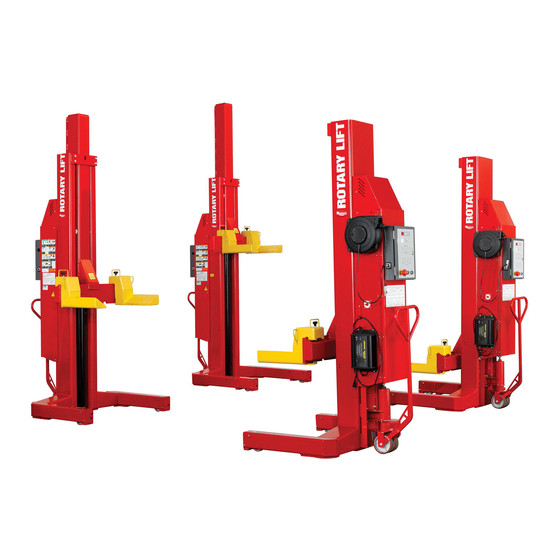
MCH418/MCH618
Four Post/Six Post Mobile Column Lift
24V DC Powered
MCH418 Capacity 72,000 lbs.
MCH618 Capacity 108,000 lbs.
18,000 lbs. per column
Reference ANSI/ALI ALIS,
Safety Requirements for
I
I
N
N
S
S
T
T
A
A
L
L
L
L
A
A
T
T
I
I
O
O
N
N
-
-
S
S
A
A
F
F
E
E
T
T
Y
Y
-
-
O
O
P
P
E
E
R
R
A
A
T
T
I
I
O
O
N
N
-
-
M
M
A
A
I
I
N
N
T
T
E
E
N
N
A
A
N
N
C
C
IN20540
E
E
Rev. G 6/12/2015
Advertisement
Table of Contents

Subscribe to Our Youtube Channel
Related Manuals for Rotary MCH418


Summary of Contents for Rotary MCH418
- Page 1 MCH418/MCH618 Four Post/Six Post Mobile Column Lift 24V DC Powered MCH418 Capacity 72,000 lbs. MCH618 Capacity 108,000 lbs. 18,000 lbs. per column Reference ANSI/ALI ALIS, IMPORTANT Safety Requirements for Installation and Service of Automotive Lifts before installing lift. © June 2015 by Vehicle Service Group. All rights reserved. CO9304.4 IN20540 Rev.
-
Page 2: Table Of Contents
Close lift and re-install M8 BHCS removed earlier. controls for easy access. After the batteries and fluid have been added, screw M20 1. Unloading: Rotary’s Mobile Lift System units are shipped bolt and M10 socket head bolts clockwise on wheel jack in the vertical position. - Page 3 Do Not Exceed Torque Values IMPORTANT On Bleeder Screw Torque Values: 177-230 In/Lbs (20Nm-26Nm) Bleed Screw Power Unit Tank IMPORTANT! Negative Post Must Be Located On This Side Battery Locations Fig. 1 M20 Bolt Adjust For Ground Clearance Socket Head Adjust For DO NOT use on asphalt.
-
Page 4: Safety Instructions
Use only qualified lift service personnel and genuine • Load vehicle on lift carefully. Position lift forks to Rotary parts to make repairs. fully contact the vehicle tires. Release parking • Thoroughly train all employees in use and care of lift, break on vehicle. -
Page 5: Quick Start Operating Instructions
Quick Start Operating Instructions Control Panel Diagram Data Information Display and Buttons Height Limit Setting Battery Charge Indicator Lights on/off (Optional Accessory) Yellow, Green, Red Activation LED’s (8 Total) System Configuration Lock/Unlock Activate Column Buttons (8 Total) Single/Pair/All Mode Raise Lower To Locks E-Stop Lower... - Page 6 Communication Fig. 2 Cable Reel DO NOT RUN CABLES IN EXIT DO NOT RUN CABLES IN EXIT PATH OF AUTOMOBILE PATH OF AUTOMOBILE Power Up Switch ROTARY LIFT EXPRESS Fig. 4 Fig. 3...
-
Page 7: Emergency Lowering
Do Not go under vehicle unless all tires are in secure Before attempting to lift any vehicle, be WARNING contact with forks. Lower lift and repeat vehicle and/or lift sure that: spotting and loading procedure if required. A. Vehicle individual axle weight does not exceed two lift columns combined capacity. -
Page 8: Detailed Operating Instructions
Height Limit Setting Button to turn the stop on and off. respond to motion commands until activated. When turned on, the system will stop whenever any column Red fast flash– indicates a column with an error. reaches the memorized height stop. *Maximum operation pressure is: 2755 psi for MCH418, MCH618... -
Page 9: Battery Charging
Battery Charging WARNING RISK OF EXPLOSIVE GASES WORKING IN THE VICINITY OF A LEAD ACID BATTERY IS 1. Battery chargers can be plugged in nearly continuously DANGEROUS. BATTERIES CONTAIN SULFURIC ACID AND or as needed. Life of the battery can be prolonged if the PRODUCE EXPLOSIVE GASES. -
Page 10: Maintenance Instructions
Maintenance Instructions • Monthly: Examine Cords: Check the condition of the If you are not completely familiar with WARNING charging cord and the communication cords on each automotive lift maintenance procedures Stop: contact column. Replace worn or broken cords as required. factory for instructions. -
Page 11: Trouble Shooting
TROUBLE SHOOTING Code Description Troubleshooting steps CPU error The processor has detected an error. Press “x” to clear. If the problem continues, call for service. Improper configuration The column has not been assigned a position, and is connected to a locked system. -
Page 12: Lift Lockout/Tagout Procedure
The responsibility for assuring that this procedure is followed is binding upon all employees and service personnel from outside service companies (i.e., Authorized Rotary Installers, contactors, etc.). All employees shall be instructed in the safety significance of the lockout procedure by the facility owner/manager. Each new or transferred employee along with visiting outside service personnel shall be instructed by the owner/manager (or assigned designee) in the purpose and use of the lockout procedure. -
Page 13: Wiring Diagram
COLUMN WIRING DIAGRAM Black... - Page 14 THIS PAGE INTENTIONALLY LEFT BLANK...
- Page 15 THIS PAGE INTENTIONALLY LEFT BLANK...
- Page 16 Please return this booklet to literature package, and give to lift owner/operator. Thank You Trained Operators and Regular Maintenance Ensures Satisfactory Performance of Your Rotary Lift. Contact Your Nearest Authorized Rotary Parts Distributor for Genuine Rotary Replacement Parts. See Literature Package for Parts Breakdown.
Need help?
Do you have a question about the MCH418 and is the answer not in the manual?
Questions and answers