Table of Contents
Advertisement
Advertisement
Table of Contents

Subscribe to Our Youtube Channel
Related Manuals for LiteOn EVO600021S0D2E20F


Summary of Contents for LiteOn EVO600021S0D2E20F
-
Page 2: Table Of Contents
Table of Contents 1.1 General Safety............................5 1.1.1 Usage ..............................5 1.1.2 Receiving ............................5 1.1.3 Installation ............................5 1.1.4 Wiring ............................... 5 1.1.5 Operation ............................6 1.1.6 Maintenance ........................... 7 1.2 Warning Label ............................7 1.3 AC Drive Application Precautions ......................8 1.3.1 AC Drive Selection ......................... - Page 3 4.3.1 Control Circuit Terminals ......................28 4.3.2 Control Circuit Wiring ......................... 29 4.3.3 Control Circuit Cable Size and Tightening Torque............... 29 4.3.4 Ferrule-Type Terminals ....................... 30 4.4.1 NPN and PNP Mode Selection ....................31 4.5 Wiring Checklist ............................33 Chapter 5│Keypad ..............................34 5.1 Check before Operation ........................
- Page 4 9.2.1 Environment ..........................171 9.2.2 Voltage ............................171 9.2.3 Keypad Monitor ......................... 171 9.2.4 Enclosure ............................. 171 9.2.5 Main Circuit ..........................172 9.2.6 Main Circuit- Terminals & Cables ................... 172 9.2.7 Main Circuit- Capacitors ......................172 9.2.8 Main Circuit- Resistors ......................173 9.2.9 Main Circuit- Magnetic Contactors &...
-
Page 5: General Safety
Chapter 1│Safety 1.1 General Safety Safety Information: Warning: Indicates highly dangerous consequences such as fire, serious injury and death when failing to comply with the instructions. Caution: Indicates dangerous consequences such as moderate injury and equipment damage when failing to comply with the instructions. 1.1.1 Usage Danger The drive is used to control the speed of 3 phase synchronous and asynchronous... -
Page 6: Operation
1. Allow only qualified electrical engineers to install the drive. Failure to comply could cause electrical shocks to personnel or damage to the drive. 2. Ensure the power supply is off when connecting. Failure to comply could cause electrical shocks. 3. -
Page 7: Maintenance
Do not start or stop the drive by connection or disconnection the power supply. Failure to comply could cause drive damage. Ensure the motor and equipment are in proper use before operation. Failure to; comply could damage the equipment. The temperature of the braking resistor and heatsink could be very high during operation. -
Page 8: Ac Drive Application Precautions
Read the user manual before operation. Risk of electrical shock. Shut off main power and wait for 5 minutes before servicing. Hot surface. Risk of burn. Warning Label 1.3 AC Drive Application Precautions 1.3.1 AC Drive Selection 1.3.1.1 Drive Capacity Before driving motors, ensure the motor rated current is lower than the drive rated output. -
Page 9: Settings
The motor characteristics at start and during acceleration are limited by the drive overcurrent. If higher starting torque is needed, use a higher rating drive or increase capacity of both motor and drive. 1.3.1.3 Emergency Stop When a drive fault occurs, protection function will be automatically triggered to shut off the output but the motor may not stop immediately. -
Page 10: Warranty
Capacitors in the drive may still be charged for a short time after shutting off the power. Wait for the amount of time specified on the drive before any maintenance. Failure to comply could cause electrical shocks to personnel. Besides, do not touch the heatsink which can be very hot during operation. -
Page 11: Chapter 2│Product
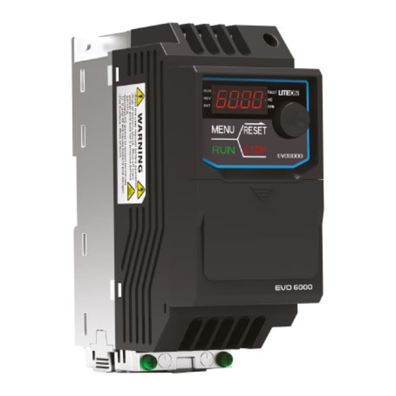
Chapter 2│Product 2.1 Component Names A – Heatsink D – Conduit bracket B – Cooling fan E – RJ45 port C – Fan guard F – Keypad 2.2 Receiving Checklist Check the following when receiving the drive: Is the packaging box in good condition? Any damage or damp ? If so, contact the distributor or local Lite-On representative. -
Page 12: Nameplate
2.3 Nameplate Model Number Applicable motor rating Input power supply Output power supply 2.4 Model Number Definition 6000 Version: Keypad Type: Filter: Product Series: E: LED S: Standard □ : No Filter EVO: Lite-On AC Drive F: Filter Built-In Series Name Enclosure: 20: IP20 Power Ratings:... -
Page 13: Power Ratings
2.5 Power Ratings 200V Class Model No. EVO600021S 0.25 Max. Motor Capacity 0.75 Voltage (V) / Single Phases, 200 ~240 V, -15% ~ +10% , 50/60Hz Rated Frequency (Hz) Input Current(A) 13.5 Current(A) Output Rated 0 to 400 Hz Frequency(Hz) Output Carrier Frequency 2 to 12kHz... -
Page 14: Common Specifications
2.6 Common Specifications Item Specification Control Method V/F Control, Sensorless Voltage Vector Control(SVVC) Ouput Frequency 0~400 Hz Digital Input: within ±0.01% of the Max. output freqeuncy Frequency Accuracy Analog Input: within ±0.1% of max. output frequency(-10℃ ~ +50℃) Frequency Setting Digital input: 0.01Hz Resolution Analog Output: 1/1000 of max. -
Page 15: Product Dimensions
Under 5000A. Relatively maximum voltage is 480 V circuit. Certificate UL 508C, CSA C22.2 no .14, IEC 61800-5-1, IEC 61800-3 *1. Results tested in labs 2.7 Product Dimensions Frame Size 1: EVO600021S0D2E20F, EVO600021S0D4E20F, EVO600021SD75E20F, EVO600043S0D4E20F, EVO600043SD75E20F, EVO600043S1D5E20F Frame Size 2: EVO600021S1D5E20F, EVO600021S2D2E20F, EVO600043S2D2E20F, EVO600043S3D7E20F Frame Size 1... - Page 16 Frame Φ Series 72[2.83] 59[2.32] 174.2[6.86] 151.6[5.97] 135.6[5.34] 5.4[0.21] 5.4[0.21] EVO6000 100[3.94] 89[3.50] 174.2[6.86] 162.6[6.41] 135.6[5.34] 5.8[0.23] 5.4[0.21]...
-
Page 17: Chapter 3│Drive Installation
Chapter 3│Drive Installation 3.1 Installation Environment To ensure the optimum drive performance, install the AC drive in a proper environment specified below. Environment Conditions Area of Use Indoors -10°C to +50°C (IP20 enclosure) Do not install the drive in environments with wide temperature fluctuations ... -
Page 18: Installation Direction And Spacing
3.2 Installation Direction and Spacing 3.2.1 Installation Direction Install the AC drive upright for better cooling. c. Transverse installation b. Horizontal installation a. Upright installation Figure 3.1 Installation Direction 3.2.2 Installation Spacing 3.2.2.1 Single Drive Installation Install the AC drive as illustrated below to ensure the required space for airflow and wiring. Figure Installation Spacing... -
Page 19: Keypad And Terminal Cover Installation
3.3 Keypad and Terminal Cover Installation It is not necessary to remove the keypad before wiring. You just need to loosen the terminal cover screw and remove the terminal cover. After wiring, affix the terminal cover back in position and tighten the screw. For wiring instructions and screw tightening torque please refer to Chapter 4. -
Page 20: Wiring Protection
3.4 Wiring Protection 3.4.1 Drive and Input Cable Protection for Short-Circuit Situations Protect the drive and input power cable by using fuse in case potential short-circuit situations cause overheat. Please refer to the following figure for proper wiring. Input cables Fuse Motor Figure 3.4 Fuse Installation... -
Page 21: Chapter 4│Wiring
Chapter 4│Wiring 4.1 Wiring Safety Danger Turn off all the power to the equipment before wiring. Wiring during power on could cause electrical shocks to personnel. Allow only qualified personnel for installation, wiring, repairing and parts replacement. Capacitors in the drive may still be charged for a short time after shutting off the power. Wait for the amount of time specified on the drive before any maintenance. - Page 22 4.2 Main Circuit Ensure the Stall Prevention function is off when using a braking unit ...
-
Page 23: Main Circuit Terminal
4.2.1 Main Circuit Terminal Braking Unit (option) MCCB MC R/L 1 U/T 1 S/L 2 V/T 2 T/L 3 W/T 3 Fast Acting Fuse Table 4.2.1 Main Circuit Terminals Terminal Name Terminal Description R/L1, S/L2, T/L3 Power input terminal U/T1, V/T2, W/T3 Power output terminal +, - Braking unit terminal. - Page 24 and W respectively. Ensure the motor and drive terminals are in same phase sequence or the motor will rotate reversely. Do not connect power cable to output terminals of the drive. Failure to comply could cause drive damage and a fire. 4.2.2.3 Braking Unit Terminal: If the drive is used in a high-frequency or heavy duty application which requires frequent ...
-
Page 25: Main Circuit Cable Size And Tightening Torque
Follow the instructions below to remove the jumper if an even lower current leakage to a even lower level. Removing the jumper may increase the signal interference. 1. Front right corner of the machine, remove the screw using a screwdriver. 2. - Page 26 W, PE (12-14) R, S, T, U, V, 16.3-19.3 Frame 2 10 to 8 5.3 to 0.8 8.4 to 0.8 W, PE (14-17) Frame 1 200V: EVO600021S0D2E20F, EVO600021S0D4E20F, EVO600021SD75E20F, 400V: EVO600043S0D4E20F, EVO600043SD75E20F, EVO600043S1D5E20F Frame 2 200V: EVO600021S1D5E20F, EVO600021S2D2E20F, 400V: EVO600043S2D2E20F, EVO600043S3D7E20F...
-
Page 27: Control Circuit
4.3 Control Circuit RJ45 port can be connected to the built-in RS-485 communication or option communication cards (options cards are under development) Multi-function analog input S1 to S6 can be switched between Sink (NPN) mode and Source (PNP) mode. The default setting is NPN mode. DIP switch A1 is used to set the analog input type as voltage or current. -
Page 28: Control Circuit Terminals
+V is the input terminal for auxiliary power. 4.3.1 Control Circuit Terminals 4.3.1.1 Input Terminals Table 4.3.1.1 Control Circuit Input Terminal Terminal Terminal Type Terminal Name Terminal Description Code Digital input terminal 1 (forward/stop) Digital input terminal 2 (reverse/stop) Photocoupler, 24 V, 8 mA. -
Page 29: Control Circuit Wiring
shorten the relay terminal life. 4.3.2 Control Circuit Wiring The applicable functions in parameter Group E can be assigned to multi-function digital inputs (S1 to S6), multi-function relay outputs (R1), multi-function analog input (A1) and multi-function analog output (FM). The default settings are listed in Figure 4.3.1.1 and Figure 4.3.1.2. -
Page 30: Ferrule-Type Terminals
4.3.4 Ferrule-Type Terminals Always use ferrule-type terminals with insulated sleeves. Refer to Table 4.3.3.2. for dimensions. In addition, crimping tool CRIMPFOXZA-3 manufactured by Phoenix Contact is recommended. Table 4.3.3.2 Ferrule-Type Terminal Models and Sizes Cable Size Type Manufacturer mm2 ( AWG) ( mm) ( mm) ( mm) -
Page 31: Npn And Pnp Mode Selection
4.4 I/O Connections 4.4.1 NPN and PNP Mode Selection Use Sink/Source DIP switch on the control board to set NPN/PNP (Sink/ Source) mode for multi-function digital inputs S1 to S6. (Default: NPN mode) Figure 4.4.1 NPN/PNP (Sink/Source) DIP Switch... - Page 32 4.4.2 Terminal A1 Voltage/Current Input Selection Select voltage or current input at terminal A1 To select current as the input type, set DIP switch A1 to I and set parameter E3-00 to 0 (0 to 20 mA) or 1 (4 to 20 mA). To select voltage as the input type, set DIP switch A1 to V and set parameter E3-00 to 2 (0 ...
-
Page 33: Wiring Checklist
4.5 Wiring Checklist Table 4.6 Wiring Checklist □ Item Page Power Supply Voltage and Output Voltage □ 1 Power supply voltage is within the voltage range of specified drive input. □ 2 The motor voltage matches the drive output specifications. □... -
Page 34: Chapter 5│Keypad
Chapter 5│Keypad 5.1 Check before Operation Make sure the main circuit is properly wired. R/L1, S/L2 and T/L3 are power input terminals which cannot be mixed with U/T1, V/T2, W/T3. Failure to comply could cause damage to the AC drive. Make sure the ground terminal is properly wired. -
Page 35: Keypad
5.3 Keypad Use the keypad to enter RUN and STOP commands, display data, fault, alarm and set parameters. 5.3.1 Keys and Displays Figure 5.1.1 Keypad... - Page 36 Table 5.3.1 Keypad Keys and Displays Display Name Function Enters or exits the parameter group MENU Key Switches the displayed menu RUN Key Forward/reverse selection STOP Key Stops the drive. Refer to Table 5.1.2.2 Moves the cursor to the right RESET Key Resets the drive to clear a fault situation Press it as “...
-
Page 37: Keypad Display
5.3.2 Keypad Display 5.3.2.1 LED Display Table 5.3.2.1 LED Display Number Number Number Number /Letter /Letter /Letter /Letter Display Display Display Display... - Page 38 5.3.2.2 LED Indication Table 5.3.2.2 LED Indication Indicator Light Blinking Drive in deceleration Output frequency Drive in operation Drive not in operation below the minimum frequency Rotating reversely Allows Run commands only from a remote source During fault Normal operation Displaying output frequency...
-
Page 39: Keypad Programming
5.3.3 Keypad Programming Keypad Display Menu Structure A. Standard setting mode: Press MENU to switch among monitor group, A1-00 parameter group and A2-00 user-defined parameter group. Press ENTER, MENU, Non-slip setting dial, and RESET to monitor and edit settings. B. -
Page 40: Chapter 6│Parameters
Chapter 6│Parameters 6.1 Group A, Initialization Sets the initial parameters (group A parameter) such as Access Level Selection, password and etc. A1 Initialization A1- 00 Retain A1- 01 Access Level Selection Selects access level (edit/ view) Name Setting Range Default A1-01 Access Level Selection... - Page 41 0 : Open-Loop V/F Control This method is recommended for those applications without the need of fast response, accurate speed control. Select this method also when using a single drive to run more than one motors, the motor parameters are unknown or Auto-Tuning cannot be performed. The speed control range is 1 : 40.
- Page 42 2541: Resets 2-Wire Sequence / 50Hz / 415V 2544: Resets 2-Wire Sequence / 50Hz / 440V 2546: Resets 2-Wire Sequence / 50Hz / 460V 2638: Resets 2-Wire Sequence / 60Hz / 380V 2641: Resets 2-Wire Sequence / 60Hz / 415V 2644: Resets 2-Wire Sequence / 60Hz / 440V 2646: Resets 2-Wire Sequence / 60Hz / 460V 3538: Resets 3-Wire Sequence / 50Hz / 380V...
- Page 43 Name Setting Range Default A1-04 Password 0000 to 9999 0000 A1-05 Password Setting ■ Password and Password Setting · Once the password other than 0000 is set to A1-05, user cannot edit A1-01 to A1-03, A2-00 to A2-15. Enter the correct password in A1-04 to unlock parameter access. ·...
- Page 44 Press to enter A1-04 setting. “nULL”is not displayed anymore as the password has been set. to enter the correct password. ( 1234 is an example) Press The display leaves A1-04 setting automatically as the parameters are unlocked. A2- 00 to A2- 15 User-Defined Parameters 1 to 16 ...
-
Page 45: Group B, Application
6.2 Group b, Application b1: Operation Mode Selection b1- 00 Frequency Command Selection 1 Selects the frequency command source for the REMOTE mode. Note: When the run command is input with 0 Hz frequency command or below the minimum frequency, the RUN ... - Page 46 AC Drive 10V,20mA power supply 0 to 10V Main frequency command 2kΩ (voltage input) Analog input common -10V,20mA power supply Figure 6.1 Setting Frequency Command as a Voltage Signal at Terminal A1 Wire all the analog input terminals according to Figure 6.1. Ensure DIP switch A1 is placed to V (voltage).
- Page 47 Dip Switch A2 AC Drive 10V,20mA power supply A1 Main frequency gain 0 to 20mA or 4 to 20mA Analog input common -10V,20mA power supply Figure 6.2 Setting Frequency Command as a Current Signal at Terminal A2 Ensure DIP switch A1 is place d to I (current). □...
- Page 48 1 : Control Circuit Terminal Allows the run command via the digital input terminals using the following sequences. □ 2-Wire Sequence Two inputs (forward/stop, reverse/stop). Set E1-00 (Terminal S1 Function Selection) to 0 (Forward/Stop) and E1-01(Terminal S2 Function Selection) to 1(Reverse/Stop). Refer to Page 112 for instructions.
- Page 49 Run Command Output Frequency Deceleration Time d1-08 Min. Output Frequency DC Braking b2-00 Zero Speed Holding Start Frequency b2-03 (DC Braking Time at Stop) Figure 6.3 Ramp to Stop Note: If the b2-00 value is smaller than the d1-08 value, DC Braking is enabled when the output frequency falls below the d1-08 value.
- Page 50 When a Stop command is given, the drive will enter the current set to b2-01 to the motor after waiting the minimum baseblock time set to P2-01. DC Braking to Stop significantly shorter the stopping time compared to Coast to Stop. Run command b2-01 DC Braking current Output frequency...
- Page 51 3 : Coast to Stop with Timer When a Stop command is given, the drive shuts off its output and the motor will coast to stop. The drive will ignore any Run command until the wait time (t) ends. Run command Output frequency Drive output shut off Wait time t...
- Page 52 terminal input E1-□□= 3 (LOCAL/REMOTE Selection), E1-□□= 4 (Command Source 1/2 Selection) . Refer to parameter group E1 and LO/RE Key Function Selection (o2-00). Enables or disables the protection to avoid an active Run command at the new source causing a sudden movement on the motor when the command source is switched from the old source to the new source.
- Page 53 Determines to accept or ignore an active Run command from Remote during power up. Name Setting Range Default b1-10 Run Command at Power up 0 : Ignore Drive ignores an active run command during power up. Note: The LED indicator blinks when there is an active Run command from Remote during power up. The drive can start only when the Run command is removed and entered again.
- Page 54 Forward and Reverse cannot be switch from keypad 1 :Enable Forward and Reverse can be switch from keypad b2 DC Braking b2-00 Zero Speed Holding (DC Braking) Start Frequency Sets the start frequency for Zero Speed Holding (DC braking). Enabled when b1-02 (Stopping Method Selection) is set to 0 (Ramp to Stop) Name Setting Range...
- Page 55 Therefore do not set this value higher than the level necessary to hold the motor shaft. b2- 02 DC Braking Time at Start Sets the DC braking time at start to stop a coasting motor before restarting it or to apply braking torque at start when a high starting torque is needed.
- Page 56 b3- 02 Retain b3- 03 Speed Search Waiting Time Name Setting Range Default b3-03 Speed Search Waiting Time 0.0 to 100.0 s 0.2 s b5 PID Control PID control utilizes Proportional, Integral and Derivative Control to minimize the deviation between the PID target and feedback.
- Page 57 Control Fluid Control Feeds back flow data to keep a constant flow level Flow rate sensor Temperature Feeds back temperature data to maintain a constant Thermistor, thermocoupler Control temperature by control the fan speed. ■ PID Target Input Methods The PID target can be input according to the methods showed in Table 6.6. If more than one PID targets are input, it will be selected as per the priority.
- Page 58 PID Differential Feedback Source Settings Terminal A1 Set E3-01 to 10 (differential feedback) Terminal A2 Set E3-07 to 10 (differential feedback) Note: When more than one PID feedback differential input source is assigned, oPE09 fault will be triggered. ■ PID Block Diagram 頻率指令...
- Page 59 PID control is enabled. D (Derivative) control the deviation signal (U4-01) between the target and feedback as output frequency. 2 : Output Frequency = PID Output 2 PID control is enabled. D (Derivative) control the feedback signal (U4-05) as output frequency. 3 : Output Frequency = Frequency Command+ PID Output 1 PID control is enabled.
- Page 60 Deviation Time PID Control D Control I Control PID Input P Control Time I Control Eliminates Deviation Feedback Feedback Target Target Deviation Feedback Feedback Time Time Figure 6.17 Relationship between Time and Deviation b5- 03 Integral Time (I) Limit Setting ...
- Page 61 Sets the upper limit of output from PID control as a percentage of the maximum frequency. Name Setting Range Default b5-05 PID Output Limit 0.0 to 100.0% 100.0% b5- 06 PID Bias Voltage Adjustment Sets the PID bias voltage adjustment as a percentage of the maximum frequency to add to the PID control output.
- Page 62 b5-27=1) Name Setting Range Default b5-10 PID Output Reverse Selection 0, 1 0 : Reverse Disabled Negative PID output will be limited to 0 and stop the drive. 1 : Reverse Enabled The drive will run reversely if PID output is negative. ■...
- Page 63 High Detection. b5- 11 PID Feedback Low /High Detection Selection Sets the feedback low /high detection and the operation when it is detected. Name Setting Range Default b5-11 PID Feedback Low /High Detection Selection 0 to 5 0 : Multi-Function Output Only A multi-function output set for E2-□□= 40 (PID feedback low) will be triggered if the PID feedback value is lower than the detection level set to b5-12 for longer than the detection time set to b5-13...
- Page 64 4 : Feedback Failure Alarm, ever if PID is Disabled Same action as b5-11=1. 5 : Feedback Failure Fault even if PID is Disabled Same action as b5-11=2. 6 :Multi-Function Output, it continue to operate and light failure is not displayed A feedback loss condition is detected when the PID feedback value falls below the value set in parameter b5-12 (PID feedback loss detection level) for the time set in parameter b5-13 (PID feedback loss detection time), E2- □□...
- Page 65 frequency command exceeds the set level for longer than the set time. PID Sleep operation is illustrated below. PID Output b5-14 PID Sleep Start Level Sleep Delay b5-15 b5-15 Sleep Delay Time Time Internal Run Command Stop External Run Command Run Command Enabled During Run Continues to Output “During Run”...
- Page 66 since it is applied after the PID output. This PID Acc./Dec. time prevents the overshoot, undershoot and hunting caused by the decreased response. In addition, set a lower value to parameter group C1 to avoid hunting. This parameter will be disabled if a multi-function input is assigned to E1-□□= 49 (PID Soft-Start On/Off).
- Page 67 3 : User Defined Displays the PID target in the units defined by b5-24 and b5-25 b5- 20 PID Output Lower Limit Sets the minimum possible PID controller output as a percentage of the maximum output frequency (d1-02). The lower limit is disabled when set to 0.00% Name Setting Range Default...
- Page 68 b5-24 Sets the display value when run at the maximum frequency. b5-25 Sets the number of decimal places to display.. Name Setting Range Default b5-24 PID Target Display Value 1 to 60000 b5-25 PID Target Display Digits 0 to 3 Determined by b5-19 0 ∶...
-
Page 69: Group C, Tuning
Overshoot Suppression When an overshoot occurs, reduce the derivative time set to b5-04 and increase the integral time set to b5-02. Stability after Overshoot. To immediately achieve stability after an overshoot, increase the derivative time set to b5-04 and reduce the integral time set to b5-02. Long Cycle Oscillation Suppression If the oscillation cycle is longer than the integral time set to b5-02, increase the time as the integral operation is too strong. - Page 70 decelerate from the maximum frequency (d1-02) to 0Hz. C1-00 and C1-01 are the active acceleration and deceleration times by default. Name Setting Range Default C1-00 Acceleration Time 1 0.0 to 6000.0 s <1> 10.0 s C1-01 Deceleration Time 1 C1-02 Acceleration Time 2 C1-03 Deceleration Time 2...
- Page 71 C1- 08 Fast Stop Time Sets the deceleration time when E1-□□= 21 (Fast Stop: Normal Open) or 22 (Fast Stop: Normal Closed). The input terminal does not have to be closed continuously to trigger Fast Stop. It will trigger Fast Stop even if the closure is momentary. Different from the normal deceleration, the drive cannot be restarted after entering Fast Stop until completing deceleration, remove the Fast Stop input and cycling the Run command.
- Page 72 C2-02 S-Curve Characteristic at Dec. Start C2-03 S-Curve Characteristic at Dec. End S-curve characteristics are illustrated below. Forward Reverse C2-01 C2-02 C2-03 Output C2-00 Frequency C2-00 C2-03 C2-01 C2-02 Figure 6.23 S-Curve Characteristics during Forward and Reverse Setting the S-curve will increase the actual acceleration and deceleration times. Actual acceleration time= acceleration time setting+(C2-00+C2-01) / 2 Actual deceleration time=deceleration time setting +(C2-02+C2-03) / 2 C3 Torque Compensation...
- Page 73 The motor excitation currents d-axis and q-axis are controlled separately. Torque compensation affects q-axis current only. Compensation voltage= q-axis voltage compensation (calculated by q-axis current) x C3-00 Adjustment: Normally there is no need to change this parameter setting. However, adjust this setting by scaling of 0.05 in the following situations.
- Page 74 C5 Slip Compensation The heavier the load is at IM motors, the slower the motor speed is. The Slip Compensation function can improve the speed accuracy in such situations. Note: Check if the settings of d2-00 (Motor Rated Current), d2-01 (Motor Rated Slip) and d2-02 (Motor No-Load Current) are correct before adjusting this parameter.
- Page 75 C6 Carrier Frequency C6-00 Carrier Frequency Selection Sets the switching frequency of the drive output transistors. Adjust this setting to reduce audible noise and leakage current. Note: If this level is set higher than the default setting, the drive rated current will be decreased. Name Setting Range Default...
- Page 76 frequency. Name Setting Range Default C6-01 Maximum Carrier Frequency 2.0 kHz to 12.0 kHz Determined by C6-00 C6-02 Minimum Carrier Frequency 2.0 kHz to 12.0 kHz C6-03 Carrier Frequency Proportional Gain 0 to 99 <1> <1> This setting is only enabled when C6-00=0. □...
-
Page 77: Group L, Frequency Command
Three Phase 400V Class Rated Current (A) Model 2kHz 8kHz 10kHz 12kHz 440V 0.5HP (0.4kW) 13.5 440V 1HP (0.75kW) 440V 2HP (1.5kW) C7-00 SVVC Porortional Gain According to application feature to set this gain, if the load is heavy increase the value, and vice versa to reduce this value. - Page 78 L1-00 to L1-15 Frequency Command 1 to 16 and L1-16 Jog Frequency Command The drive allows the user to switch between up to 16 frequency commands and 1 Jog frequency command. The drive uses the selected acceleration and deceleration times when switching between each frequency command.
- Page 79 Frequency Command 1 ( L1-00: set in b1-00) Frequency Command 2 L1-01 Frequency Command 3 L1-02 Frequency Command 4 L1-03 Frequency Command 5 L1-04 Frequency Command 6 L1-05 Frequency Command 7 L1-06 Frequency Command 8 L1-07 Frequency Command 9 L1-08 Frequency Command 10 L1-09 Frequency Command 11...
- Page 80 L1-15 Frequency Command L1-14 L1-13 L1-08 L1-07 L1-06 L1-05 L1-04 L1-03 L1-02 L1-01 L1-00 L1-16 Time Run/Stop Forward ( Reverse) Multi-Step Speed Command 1 Multi-Step Speed Command 2 Multi-Step Speed Command 3 Multi-Step Speed Command 4 Multi-Step Speed Command 5 Figure 6.35 Jog Frequency Command Operation Frequency Upper / Lower Limit Sets the upper and lower limits to make sure the motor runs in the range set to prevent...
- Page 81 L2-01 Frequency Command Lower Limit 0.0 to 110.0% 0.0% Output Frequency Frequency Command L2-00 Upper Limit Operating Range Frequency Command L2-01 Lower Limit Frequency Command Figure 6.36 Frequency Command Upper and Lower Limits L3 Jump Frequency L3-00 to L3-03 Jump Frequency 1 to 2/ Jump Frequency Range ...
- Page 82 The relationship between the output frequency and the Jump frequency is illustrated in the following figure. Output Frequency Frequency Frequency command Command increases Decreases L3-04 Jump Frequency Range L3-04 Jump Frequency Range L3-04 Jump Frequency Range Frequency L3-00 L3-01 L3-02 Jump Frequency 2 Jump Frequency 3 Command...
- Page 83 Name Setting Range Default L4-00 Up/ Down Frequency Command Hold 0, 1, 2 0 :Clear Up/ Down Frequency Command at Stop UP/DOWN commands via multi-function input terminals are enabled to adjust the speed only when the drive is running. The frequency command will be reset to 0 Hz when the Stop command is entered or the drive power supply is shut off.
- Page 84 Output frequency Bias value is increased using the acc./dec.times set to L4-02 Bias Up 2 command Figure 6.38 Up 2/Down 2 Bias when L4-01=0.0 Hz Setting L4-01 ≠ 0.00 Hz If the Up 2 or Down 2 command is closed for less than 2 seconds, the bias is increased or decreased using the acceleration and deceleration times defined by L4-01 ( Frequency Command ).
- Page 85 Output frequency Bias value is increasing when the acc./dec. times set to L4-02 Bias Up 2 command Less Less More than 2s than 2s than 2s Figure 6.39 Up 2/Down 2 Bias when L4-01 0.0 Hz > L4-02 Frequency Command Acc./Dec Setting ( Up / Down 2) ...
- Page 86 Saves the frequency command from Up/Down 1 or Up/Down 2. Up/Down 1 and Up/Down 2 cannot be used at the same time. If a multi-function input terminal is assigned to Up/Down 1 and Up/Down 2, an alarm will be triggered. This parameter is enabled in the following situations.
- Page 87 Power supply Forward Run/ Stop Hold Acc./Dec. Frequency Command Output L4-01 = 1 Frequency L4-01 = 0 Hold Hold Figure 6.40 Frequency Command Hold with Acc./Dec. Hold L6 Offset Frequency L6- 00 to L6- 02 Offset Frequency 1 to 3 ...
-
Page 88: Group D, Motor Parameters
Frequency Frequency Soft-start command command after soft-start Multi-function input E1-□□ = 53 = ON L6-01 Offset Frequency 1 (Signed) Multi-function input E1-□□ = 54 = ON L6-02 Offset Frequency 2 (Signed) Multi-function input E1-□□ = 55 = ON L6-03 Offset Frequency 3 (Signed) Figure 6.41 Offset Frequency Operation... - Page 89 Setting ≥ 820 V 790 V 380 V 400 V 400 V Setting< 820 V 790 V 350 V 400 V <1> The braking transistor operation level. ■ V/F Pattern Setting( d1-01) The set V/F pattern determines the output voltage according to the frequency command. There are 15 different preset V/F patterns (setting 0 to E: only the maximum voltage and base voltage can be changed) and user-defined V/F patterns d1-02 to d1-11 (setting F).
- Page 90 · Large starting torque is required such as 60 Hz, mid starting torque elevators. · AC reactor is installed on the drive output 60 Hz, high starting torque side 90 Hz (with 60 Hz base) Fixed Output Constant output voltage when running at 60 Hz and above.
- Page 91 1.3 2.5 1.5 3.0 Table 6.17 Fixed Output Characteristics (Setting C to F) Setting =C 90 Hz Setting =D 120 Hz Setting =E 180 Hz 1.5 3 0 1.5 3 0 1.5 3 User-Defined V/F Patterns (Default : F) When d1-01 = F, d1-02 to d1-11 can be set to create a new pattern. d1-02 to d1-11 will be same as V/F pattern setting 1 after reset.
- Page 92 Output Voltage (V) d1-03 d1-11 d1-05 d1-07 d1-09 d1-08 d1-06 d1-04 d1-10 d1-02 Frequency (Hz) Figure 6.42 V/F Pattern Note: When setting an user-defined V/F pattern, make sure d1-08 ≤ d1-06 < d1-04 ≤ d1-10 ≤ d1-02. d2 Motor Parameters d2 parameters set the important motor information required to perform optimum motor control.
- Page 93 Name Setting Range Default d2-01 Motor Rated Slip 0.00 to 20.00 Hz Determined by o2-03 If Auto-Tuning cannot be performed, use the information shown on the motor nameplate to calculate the motor rated slip by the following formula. d2-01=f-(n‧p)/120 f ∶rated frequency (Hz), n ∶ motor rated speed ( min-1), p ∶ number of motor poles d2- 02 Motor No-Load Current ...
- Page 94 Name Setting Range Default d2-05 Motor Leakage Inductance 0.00 to 650.0 mH Determined by o2-03 ■ d2- 06 Motor Rotor Resistance Sets the motor rotor resistance. This will be set automatically during Auto-Tuning. Name Setting Range Default 0.000 to 65.00 Ω d2-06 Motor Rotor Resistance Determined by o2-03...
-
Page 95: Group E, Multi-Function Terminals
□ Motor No-Load Current Setting Sets the motor no-load current when running at no-load voltage and rated frequency. This information is not written on the motor nameplate. Contact the motor manufacturer for the information. □ Number of Motor Poles Setting d2-03 is only enabled in Closed-Loop V/F Control and Closed-Loop Vector Control. - Page 96 Setting Functions Setting Functions 2-Wire Sequence Control Retain (Forward/Stop) 2-Wire Sequence Control Retain (Reverse/Stop) 3-Wire Sequence Retain Local/Remote Selection Retain Retain Communication Mode Multi-Step Speed Command 1 PID Disable Multi-Step Speed Command 2 PID Integral Reset Multi-Step Speed Command 3 PID Integral Hold Multi-Step Speed Command 4 PID Soft-Start On/Off...
- Page 97 External Fault 12 External Fault 13 External Fault 14 External Fault 15 External Fault 16 Fault Reset oH2 (AC drive Overheat Alarm) 0 : Forward/ Stop 1 : Reverse/ Stop 2 : 3-Wire Sequence Control The multi-function input terminal S3 to S6 can be assigned to 3-Wire Sequence Control to be the input terminal for Forward/ Reverse Command.
- Page 98 Note: 1. When entering a Run command, close the terminal for minimum 2 ms. 2. If the Run command is active at power up and b1-10 (Run Command at Power up)= 0 (Ignore), the protection will be triggered and LED indicator will flash. Set b1-10 (Run Command at Power up)=1 (Accept) to accept an active Run command at power up.
- Page 99 9 : Jog Frequency The Job frequency set by L1-16 is enabled when the terminal is closed. And the acceleration and deceleration time will be the values set to C1-11 and C1-12. 10/ 11 : Up/Down Command Allows the frequency command to be set to two external terminals. Always set E1-□□= 10 (Up Command) and E1-□□= 11 (Down Command) in pair.
- Page 100 Output frequency upper limit L4-00=1 Acceleration to lower limit Same frequency L4-00=0 Output frequency lower limit Forward run/ stop Up command Held frequency reset Down command Power supply Figure 6.46 Up/ Down Command Operation 12/ 13: Up2/ Down 2 Command Increases or decreases the frequency command bias.
- Page 101 L1-16 Output Frequency L1-16 FJOG RJOG Figure 6.47 FJOG/ RJOG Command Operation 16 : Acc./Dec. Time Selection 1 Switches between C1-00, C1-01 (Acc./Dec. Time 1) and C1-02, C1-03 (Acc./Dec. Time 2) by opening or closing the terminal. Refer to C1-00 to C1-07 (Acc./Dec. Time 1 to 4) for details. 17 : Acc./Dec.
- Page 102 command Baseblock Baseblock release command Frequency command Speed Search started from the previous frequency command Output Frequency Drive output shut off, motor coasts Figure 6.48 Baseblock Operation Drive Operation Input Setting 19 (Normal Open) Setting 20 (Normal Closed) Normal operation Open Closed Baseblock (drive output shut off)
- Page 103 will be shut off the motor will coast resulting uncontrolled motor state. To avoid this, set an appropriate deceleration time to C1-08. 23 to 38 : External Fault Stops the drive when problems occur with external devices. To use the external fault function, set E1-00 to E1-05=23 to 38. While an external fault is triggered, EF□...
- Page 104 39: Fault Reset When a fault is detected, close the assigned terminal output, shut off the drive output and stop the motor. Most of the faults cause the motor to coast, but stopping method can be set for some faults (e.g. P1-03 Motor Overheat Fault Operation Selection). To restart the drive, either remove the Run command, press the RESET key ( ) on the keypad, or set 39 (Fault Reset) to any terminal input in E1-00 to E1-07 and close the terminal input.
- Page 105 53/54/55 : Offset Frequency 1/ 2/ 3 Adds offset frequencies L6-00 to L6-02 to the frequency command when the terminal is closed. Refer to L6-00 to L6-02 (Offset Frequency 1/ 2/ 3). 56 to 59: Retain 60 : Program Lockout When the input terminal is closed parameter settings can be changed.
- Page 106 65 : DC Braking Stops the motor during deceleration. When a Run command or Jog command is entered, the DC braking will be removed as illustrated in the following figure. Refer to b2 (DC Braking) for details. DC braking command command DC braking DC braking...
- Page 107 Table 6.20 Multi-Function Output Terminal Settings Setting Function Setting Function During Run Retain Zero Speed Holding Retain Frequency (Speed) Agree Retain User-Defined Frequency (Speed ) Agree Retain Drive Ready Retain Uv (Undervoltage) Detection Retain During Baseblock During Frequency Output Retain Drive Enabled Frequency Command Source Retain...
- Page 108 Closed A Run command is input or the drive is during DC braking or deceleration command Baseblock command Output frequency During Run Figure 6.53 During Run Operation 1 : Zero Speed Holding When the output frequency falls below the d1-08 (Minimum Output Frequency) or b2-00 (Zero Speed Holding Start Level) setting, the output terminal closes.
- Page 109 Frequency P4-01 command Output frequency or motor speed P4-01 Speed agree OFF Figure 6.55 Speed Agree Operation 3 : User-Defined Frequency (Speed ) Agree When the output frequency and frequency command are both within the P4-00 (Frequency Detection Level) level plus or minus the P4-01 (Frequency Detection Width) value, the output terminal closes.
- Page 110 entered, the output terminal closes. · When the power is cut off · During a fault · When the internal power supply of the drive malfunctions · When an improper parameter setting makes the drive unable to run · An overvoltage or undervoltage fault is triggered during stop ·...
- Page 111 11 : Fault When a fault is triggered, the assigned output terminal closes. 12 : Communication Mode If the terminal is assigned to 12, it can be the output terminal for the upper controller using Modbus communication. If the signal is not set by the controller, the signal will not perform any action.
- Page 112 Terminal Description The output frequency does not exceed the P4-00 level, or below the P4-00 level minus Open the P4-01 value. Closed The output frequency exceeds the P4-00 level Note: 1. The detection and the P4-00 level work in both forward and reverse directions. P4-01 Output P4-00...
- Page 113 Figure 6.59 During Reverse Operation 23: Retain 24: During Regeneration When the motor outputs during regeneration, the assigned output terminal closes. 25 : During Restart When the drive attempts to clear a fault during restart, the assigned output terminal closes. If the fault is cleared after restart, the output terminal opens.
- Page 114 command Baseblock command Output frequency During frequency output Figure 6.60 During Frequency Output Operation 36: Drive Enabled Shows the status of multi-function terminal input E1-□□= 69 (Drive Enabled). When the input terminal E1-□□= 69 is closed, the output terminal closes as well. 37: Retain 38 : Local/Remote Mode The output terminal closes in Local mode and opens in Remote mode.
- Page 115 44 : During Fast Stop The assigned output terminal closes during a fast stop. Refer to setting 21 and 22 (Fast Stop) of multi-function Digital Inputs. 45 to 47 : Retain 48:During Wobble operation The assigned output terminal closes during wobble function operation. 49:Retain Multi-Function Analog Input The drive has two multi-function analog inputs (A1).
- Page 116 E3-02/ E3-03 Terminal A1 Input Gain/ Voltage Bias E3-02 sets the terminal A1 input gain as a percentage when inputting 10V. E3-03 sets the terminal A1 input voltage bias as a percentage when inputting 0V. Terminal A1 input characteristics are determined by E3-02 and E3-03. Name Setting Range Default...
- Page 117 E3-00 = 0 E3-00 = 1 Gain = 100% Gain = 100% Frequency -10 V -6 V command E3-00 = 0 2.0 V 10 V 10 V 2.0 V Gain = -100% Bias = -25% d1-02 E3-00 = 1 Gain = -150% Figure 6.63 Frequency Command Adjusted by Input Gain and Negative Bias ...
- Page 118 PID Feedback PID Target Differential PID Feedback Overtorque/ Undertorque Detection Retain Retain 0 : Main Frequency Command Enters the frequency command via an analog input terminal when b1-00 or b1-07=1 1 : Retain 2 : Output Frequency Lower Limit The output frequency lower limit can be adjusted by the analog input value. 3 : Auxiliary Frequency Command Sets the auxiliary frequency command 1 when multi-step speed operation is selected.
- Page 119 Acc./Dec. gain from 1 to 10 V ( 10 V ) ╳ 10 (%) Input voltage ( V ) 100% 10 V 1V 2V Figure 6.64 Acc./Dec. Time Gain Using Analog Input 6 : DC Braking (DB) Current Adjusts the DC braking current by the analog input value. When 10 V voltage or 20 mA current is input, the braking current will be 100% of the drive rated output current.
- Page 120 Stall prevention level during Run 100% Analog input level 10 V ( 4mA ) ( 8.8mA ) ( 20mA ) Figure 6.66 Stall Prevention Level Using Analog Input 8 : PID Feedback Sets the PID feedback by the analog input value. To use this function, enable the PID control in b5-00.
- Page 121 Multi-Function Analog Output These parameters assign functions to terminal FM and AM to monitor the status of the drive. E4-01 Terminal FM Monitor Selection Selects the monitor for terminal FM and AM. Name Setting Range Default E4-01 Terminal FM Monitor Selection 0 to 11 Setting Function...
- Page 122 Output voltage Output voltage Gain 150% Gain 100% Bian 0% Bias 30% Gain 100% Gain 100% Bias 0% Bias 0% Gain 50% Bias 0% Monitor value 100% 100% Monitor value Figure 6.69 Analog Output Gain and Bias Opeartion Check the setting value of E4-02, -03 when the monitor value is 100%. Example 1: When E4-02 = 80% , the voltage output to terminal FM equals to 100% resulting 8 Example 2: When E4-03 = 5% , the voltage output to terminal FM equals to 0% resulting 0.5 V.
- Page 123 E6-08 RS-485 Communication Parity Selection Name Setting Range Default E6-08 RS-485 Communication Parity Selection 0 to 3 0: 8, N, 2 (MODBUS RTU) 1: 8, N, 1 (MODBUS RTU) (available for Remote Keypad) 2: 8, E, 1 (MODBUS RTU) 3: 8, O, 1 (MODBUS RTU) ...
-
Page 124: Group P, Protections
6.7 Group P, Protections Motor Protection Function P1-00 Motor Protection Function Selection The drive has an overload protection using an electrothermal relay. The overload telarance is calculated by the output current, output frequency and thermal motor characteristics. When the motor overload is detected, an oL1 (Motor Overload) fault shuts off the drive output. Set this parameter according to the motor being used. - Page 125 1 : General-Purpose Motor (Standard Motor) The motor is self-cooled so the overload tolerance falls when the motor speed is decreased. The Electrothermal relay trigger level changes according to the motor overload characteristics to protect the motor from overheat throughout the entire speed range. Overlaod Characteristics Overload Tolerance Cooling Ability...
- Page 126 3 : Vector Motor (Constant Torque Range 1 : 100) The motor is allowed to run with 100% load from 1% to 100% speed. When the motor runs slower with 100% load, an overload fault will be triggered. Overlaod Cooling Characteristics Overload Tolerance Ability...
- Page 127 ( P1-01 = 1 minute, 60 Hz speed, general-purpose motor) · Cold start: The motor protection operation time responds to an overload situation which is suddenly reached when strating a stationary motor. · Hot start: The motor protection operation time responds to an overload situation which occurs when the motor was running continuousely at its rated current.
- Page 128 This determines the time the drive waits for the residual voltage in the motor to dissipate. Increase this value if overcurrent or overvoltage occurs at the beginning of Speed Search and DC Braking. Name Setting Range Default P2-01 P2-01 Minimum Baseblock (bb) Time 0.1 to 5.0 s Determined by o2-03 ...
- Page 129 the motor to keep up with the desired speed without changing the acceleration or deceleration times. This function can be set separately for acceleration, operating at constant speeds, and deceleration. P3- 00 Stall Prevention during Acceleration Sets the method to prevent the motor being stopped by oC(Overcurrent), oL1 (Motor Overload) or oL2 (Drive Overload) fault.
- Page 130 Sets the output current level to activate the Stall Prevention function during acceleration. Name Setting Range Default P3-01 Stall Prevention Level during Acceleration 0 to 150% <1> <1> When the motor rating is smaller than the drive rating, using the default to run the motor ...
- Page 131 1 : Enabled When the main circuit voltage exceeds the tall Prevention level during acceleration, the deceleration pauses and hold the frequency. When the main circuit voltage falls below the Stall Prevention level, the drive continues to decelerate using the set deceleration time. Stall Prevention might be triggered repeatedly to prevent an overvoltage fault.
- Page 132 1. Available in Open-Loop V/F Control, Closed-Loop V/F Control and PM Open-Loop Vector Control control methods. 2. Disable when the output frequency is below 6 Hz regardless the P3-05 and P3-06 settings. 0 : Disabled The drive runs at the set frequency command. A heavy load might cause the motor too stall and triggered an oC (Overcurrent) or oL1 (Motor Overload) to stop the motor.
- Page 133 Stall Prevention level during run 100% Input of multi- function analog input 10 V terminal A1 ( 4mA ) ( 8.8mA ) ( 20mA ) Figure 6.82 Using Analog Input to Change Stall Prevention Level during Run P3-07 to P3-10 Retain Frequency Detection P4 parameters set the frequency agree and frequency detection to the assigned multi-function...
- Page 134 Analog frequency 100% command P4-04 Frequency command loss ( E2-00 to E2-03 Time =9 ) Figure 6.83 Frequency Command Loss Detection Operation This parameter sets the drive operation when a frequency command loss is detected. Set E2-00 to E2-03 to 9 (Frequency Command Loss) for the output terminal to trigger when frequency command loss occurs.
- Page 135 P5 Fault Restart Fault Restart tries to automatically restart the motor and continue operation to prevent the motor from stopping when a fault is detected. The drive diagnoses itself and continues operation when a fault is detected during run. If the self-diagnosis is successful to clear the fault, the drive restarts automatically with Speed Search.
- Page 136 P5-00 Number of Auto Restart Attempts 0 to 10 P5- 01 Auto Restart Fault Output Operation Enables or disables the fault output via E2-□□= 11 (Fault) during Fault Restart. Name Setting Range Default P5-01 Auto Restart Fault Output Operation 0, 1 0 : Fault Output Disabled 1 : Fault Output Enabled...
- Page 137 Motor current/ torque Hysteresis Hysteresis ( 10% ) ( 10% ) P6-01 P6-02 P6-02 Torque detection 1 or 2 Figure 6.84 Overtorque Detection Operation Motor current/ torque Hysteresis ( 10% ) P6-01 P6-02 P6-02 Torque detection 1 or Figure 6.85 Undertorque Detection Operation Note: 1.
- Page 138 Overtorque detection is active when the Run command is active. The drive continues to run after an ot1 (Overtorque Detection 1) alarm is triggered. 3 : Overtorque Fault at Speed Agree Overtorque detection is active only when the output frequency is the same as the frequency command.
- Page 139 P6-01 Overtorque/ Undertorque Detection Level 1 0 to 300% 150% Note: This level can be set by the analog input terminal assigned to E3-□□=11. The analog input overrides the setting in this parameter. However P6-04 (Overtorque/ Undertorque Detection Level 2) cannot be set by the analog input terminal.
- Page 140 0 : Disabled 1 : Enabled when One Phase is Lost A LF1 (Output Phase Loss) fault is triggered when one output phase is lost. The drive output is cut off and the motor coasts to stop. 2 : Enabled when Two Phases are Lost A LF1 (Output Phase Loss) fault is triggered when more than one output phases are lost.
-
Page 141: Group O, Keypad Function Settings
Sets the cooling fan off-delay time when P7-03=0 that the drive waits to disabled the cooling fan after run command is released. Name Setting Range Default P7-04 Heatsink Cooling Fan Off-Delay Time 0 to 300 s 60 s P7-05 Ambient Temperature Setting Sets the ambient temperature. - Page 142 o1-02 and o1-03, the unit can be set to any。 Name Setting Range Default o1-00 Frequency Command 0 ~ 2 Setting/Display 0 :Use units of 0.01Hz 1 :Use units of 0.01%(100% as maximum output frequency) groupof motor poles) o1- 01 Setting Unit V / f characteristic frequency-dependent parameters ...
- Page 143 Multi-Function Selection o2 parameters determine the functions assigned to the keys on the keypad. o2-01 STOP Key Function Selection Determines if the STOP key on the keypad will stop the drive when Remote is selected as the command source. Name Setting Range Default...
- Page 144 0 : ENTER Key Required The ENTER key is required to be pressed to trigger the frequency command. 1 : ENTER Key Not Required When entering a frequency command, the output frequency changes immediately by UP or DOWN key without pressing ENTER. The frequency command will be saved 5 seconds after it is changed by pressing the UP or DOWN key.
-
Page 145: Group T, Auto-Tuning
1 ∶ Time of Run Keeps track of time when the output voltage is active. o4-06 U2 Reset Setting Resets the data for U2-□□ (Fault Information) as this data will not be reset by A1-03 (Reset). Name Setting Range Default o4-06 U2 Reset Setting... - Page 146 Sets the motor rated output power in kW units. Name Setting Range Default t1-02 Motor Output Power 0.00 to 650.0 kW Determined by o2-03 Note: The maximum motor rating the drive can run changes depending on the A1-06 (ND/HD Selection) setting. 1HP (Horse Power) = 0.746kW ...
- Page 147 t1-06 Number of Motor Poles Sets the number of motor poles according to the motor nameplate. Name Setting Range Default t1-06 Number of Motor Poles 2 to 48 t1-07 Motor Base Speed Sets the motor base speed according to the motor nameplate. Name Setting Range Default...
-
Page 148: Group U, Monitor Settings
the motor Auto-Tuning function. The display flashes in process and shows “End” after Auto-Tuning is completed. If Auto-Tuning fails, the process stops immediately and shows “tnFxx” on the screen which “xx” indicates the problems. Refer to Chapter 8.4 Auto-Tuning for more details. When the Auto-Tuning function is required to be controlled by the keypad, set b1-01(Run Command Selection 1) to 0 (Keypad). - Page 149 Parameter Name Description Unit Displays the status of the drive operation. U1-11=11111111 The following indicate each digit from right to left. 1:During Run 1:During Zero Speed Holding Drive Operation U1-11 1:During Reverse Status 1:During Fault Reset Signal Input 1:During Speed Agree 1:Drive Ready 1:During Alarm Detection 1:During Fault Detection...
- Page 150 Parameter Name Description Unit Recent Fault Operation Status at Displays the operation status at the first most recent fault. U2-15 Most Recent Fault (Same status display as U1-11) Frequency command Displays the frequency command at the second most recent U2-19 at 2 Most Recent fault.
- Page 151 1: Control Circuit Terminal (Sequence Control Input) Source Selection 3: Modbus communication 4: Communication option card 7: LiteOn Studio PC software nn: Command Limit Status 00: No limit status 01: Run command was left on when stopped in programming mode...
- Page 152 Parameter Name Description Unit 05: Fast Stop (multi-function terminal input or keypad) 06: b1-10 (Run command at power up) 07: During baseblock when coast to stop with timer 08: Frequency command is less than d1-08 (Minimum Output Frequency) during baseblock. 09: Waiting for ENTER command.
-
Page 153: Chapter 7│Options
Chapter 7│Options The following peripheral device options can be installed to improve the drive performance. Contact the local distributor to purchase the options if needed. 7.1 AC Reactor Option 7.1.1 Installing an AC Reactor The non-linear components such as rectifiers and SCRs on the drive input side will cause high harmonic input current which interrupts the power supply and affects the power factor. -
Page 154: Installing Input Fuses
7.2 Installing Input Fuses Installing fuses on the drive input side is recommended to prevent internal short circuit. Select the suitable fuses below or the branch circuit protection in compliance with local electrician regulations. 200V class single phase: Line Fuse 220V Model Input Current I (A) I (A) -
Page 155: Chapter 8│Troubleshooting
Chapter 8│Troubleshooting 8.1 Alarm and Fault Displays Table 8.1 Alarm and Fault Displays, Causes, and Possible Solutions Keypad Fault Name Cause Possible Solution Display Retain 1. Remove the cause of the external fault then reset the multi-function input. 1. An external device 2. - Page 156 Keypad Fault Name Cause Possible Solution Display Heatsink temperature 2. Internal cooling fan a. Improve the air flow inside the over 95°C stopped operating enclosure panel 3. Bad air flow due to b. Install an air conditioner or fan insufficient room. to cool the environment c.
- Page 157 Keypad Fault Name Cause Possible Solution Display main circuit lines and grounding wiring. »If the MC is the source of interference, connect a suppressor to it. 5. Reconnect the cable 6. Correct the wiring 1. Correct the drive input power wiring 2.
- Page 158 Keypad Fault Name Cause Possible Solution Display Drive Overheat Warning 1. Search the device which caused the overheat warning. Remove Drive Overheat Warning An overheat warning in the cause of the problem. input via a the drive was triggered by 2.
-
Page 159: Fault Detection
8.2 Fault Detection Table 8.2 Fault Displays, Causes, and Possible Solution Keypad Fault Name Cause Possible Solution Display Output power cable is Check and replace output power Ground Fault damaged cable 1. Increase the deceleration time settings (C1-01 and C1-03) »Install a braking unit »Set P3-03 ( Stall Prevention during... - Page 160 Keypad Fault Name Cause Possible Solution Display 8. Tighten the terminal or replace the damaged cable 9. Correct the wiring 10. Check the solutions for interference suppression 1. Check the insulation resistance 1. The motor insulation is 2. Check the motor power cable damaged or the motor is 3.
- Page 161 Keypad Fault Name Cause Possible Solution Display 10.Check the amount of torque interference causes drive compensation malfunction 11. >Find out possible solutions 11. Run command was to suppress the electrical signal applied while motor was interference. coasting >Input Speed Search command 12.
- Page 162 Keypad Fault Name Cause Possible Solution Display ( Carrier Frequency Option ) 3.Replace the cooling fan 1. Check the load, acceleration / deceleration time and cycle time a. Reduce the load Motor Overheat 1 b. Increase C1-00 to C1-03 (Acc./Dec. Time) settings The temperature 1.
- Page 163 Keypad Fault Name Cause Possible Solution Display 10. The electrical thermal 7. Confirm the rated frequency relay operates at the wrong showed on the motor nameplate level »Set d1-04 (Base Frequency) 11. Motor overheated by according to the motor overexcitation operations nameplate 12.
- Page 164 Keypad Fault Name Cause Possible Solution Display oscillation » Set a lower value to C3-00 (Torque Compensation Gain) until the current is decreased and the motor does not stall. 7. Adjust parameters related to Speed Search » Adjust b3-03 8. Check the power supply for phase loss Overtorque Detection 1...
- Page 165 Keypad Fault Name Cause Possible Solution Display Contact the local distributor for more information. Retain 1. Check wiring for errors in the main circuit drive input power »Correct wiring 2. Make sure the terminals are tightened correctly Input Phase Loss 1.
- Page 166 Keypad Fault Name Cause Possible Solution Display 3. Feedback sensor malfunction 1. Incorrect parameter settings 1. Reset b5-12 and b5-13 2. Incorrect PID feedback PID Feedback Low 2. Correct the wiring wiring 3. Check the sensor 3. Feedback sensor malfunction Retain 1.
-
Page 167: Operation Errors
8.3 Operation Errors Table 8.3 Error Displays, Causes, and Possible Solutions Keypad Error Name Cause Possible Solution Display 1. Set the parameters to the Parameter Range Parameters are set outside of oE02 proper values Setting Error the possible setting range 2. - Page 168 Keypad Error Name Cause Possible Solution Display d1-04, d1-06, d1-08, d1-09 settings 1. Contradictory settings · C6-03 (Carrier Frequency Proportional Gain)>6 · C6-02 (Minimum Carrier Frequency)> C6-01 Carrier Frequency (Maximum Carrier oE11 Correct the parameter setting. Setting Error Frequency) Note: If C6-03 ≤ 6 , the drive operates at C6-01 2.
-
Page 169: Auto-Tuning Fault Detection (Under Development)
8.4 Auto-Tuning Fault Detection (Under Development) Table 8.4 Auto-Tuning Codes, Causes, and Possible Solution Keypad Fault Name Cause Possible Solution Display User presses STOP key Do not press STOP key during TF00 Auto-Tuning Stop during Auto-Tuning Auto-Tuning The line-to-line resistance in Line-to Line Auto-Tuning is negative or TF01... -
Page 170: Chapter 9│Inspection & Maintenance
Chapter 9│Inspection & Maintenance 9.1 Safety Electrical Shock Allow only qualified electrical engineers to install the drive. Failure to comply could cause electrical shocks to personnel or damage to the drive. Ensure the power supply is off when connecting. Failure to comply could cause electrical shocks. ... -
Page 171: Periodic Inspection
9.2 Periodic Inspection Perform regular inspections according to the following check lists to ensure the optimum product performance and status. 9.2.1 Environment Inspection Cycle Inspection Points Corrective Action Daily months months Ambient temperature, humidity, Eliminate the source of contaminants or vibration, dusk, harmful gases, oil mist, ○... -
Page 172: Main Circuit
Replace the damaged components Is the color changed by the heat? ○ Replace the entire drive if necessary. Affix the terminal block cover Remove the dust with a vacuum Any dust collection or stain? cleaner ○ ... -
Page 173: Main Circuit- Resistors
9.2.8 Main Circuit- Resistors Inspection Cycle Inspection Points Corrective Action Daily months months Any odor or crack because of heat? It is normal if the color changes ○ slightly. Any disconnection? ○ Check the connection if the color Any damage at the connection? ○... -
Page 174: Cooling- Fans
9.2.11 Cooling- Fans Inspection Cycle Inspection Points Corrective Action Daily months months Any abnormal noise or vibration? ○ Are the screws all tightened? Clean or replace the cooling fan. ○ Any color change because of heat? ○ 9.2.12 Cooling- Air Duct Inspection Cycle Inspection Points Corrective Action... -
Page 175: Removing Cooling Fan
shocks when touching the motor enclosure. Do not touch any live components to avoid electrical shocks. Do not tough the terminals. Avoid output cables contacting the drive enclosure. Do not inspect or maintain the drive when waring loose clothing, jewelry or without eye protection. ... -
Page 176: Chapter 10│Drive Derating
Chapter 10│Drive Derating By derating the drive capacity, the drive can run at above the rated temperature, altitude and default carrier frequency. For example, a drive with 20 A rated current can be derated to 16A current so as to run with higher temperature tolerance. Change the carrier frequency to derate the drive. -
Page 177: Chapter 11│Communications
Chapter 11│Communications 11.1 Modbus Communication Specifications Item Specifications Interface RS-485 Communications Cycle Asynchronous Communication Parameters Communication speeds Data length Select even, odd or none Stop bit Protocol Modbus Max number of Slaves 31 AC drives 11.2 Connecting to Controller/PLC/HMI 11.2.1 Communication Cable Connection 1. -
Page 178: Modbus Setup Parameters
11.3 Modbus Setup Parameters This section explains the parameters needed for Modbus communication. E6- 06 Drive Station Address Sets the drive station address. Note: Cycle the drive power to activate the setting.. Drive Station Default: 1 E6-06 Sets the drive station address. Address Range: 1 to 31 Note: (1)When set to 0, the drive will not respond to the Modbus communication. -
Page 179: Drive Operations By Modbus
E6-09, the fault will be triggered. E6- 10 Transmit Wait Time Sets the wait time between sending and receiving data. Transmit Sets the wait time between sending and receiving Default: 5ms E6-10 Wait Time data. Range: 5 to 65 ms PLC/Controller Drive PLC/Controller... -
Page 180: Message Format
11.5 Message Format 11.5.1 Message Content In Modbus communications, the master gives commands to the slave, and the slave responds. The following table shows the configured message for both sending and receiving, and the length of data packets is determined by the command (function) content. 11.5.2 Message Configuration RTU scheme: START... -
Page 181: Error Check
register data, the drive configures consecutive data. The length of the data depends on the command details. The Modbus register always consists of a data length of two bytes. Data written into the register must also consist of a length of two bytes. Register data read out from the drive will always have two bytes. -
Page 182: Response Message
if ( wkg & 0x0001 ) { wkg = ( wkg >> 1 ) ^ 0xa001; else { wkg = wkg >> 1; return( wkg ); 11.5.8 Response Message Perform a CRC calculation on the response message according to the above description. The result of the calculation should match the CRC checksum of the response message. - Page 183 RTU Scheme: Command Message: Respond Message: Address Address Function Function Data address Data address Data content Data content CRC CHK High CRC CHK High CRC CHK Low CRC CHK Low Command code: 10H, write consecutive data to register (Max. 20 pieces of consecutive data). For example, changing the drive (address 01H) multi-step speed setting L1-00=60.00 (0880H), L1-01=50.00 (8801H).
-
Page 184: Modbus Data
respond to the upper control to inform upper control about the error. And the drive keypad displays CE-XX (XX is the error code) as the warning message. Refer to 11.8.1 Modbus Errors. Example: RTU Scheme: Address Function Exception code CRC CHK Low CRC CHK High 11.7 Modbus Data The following tables shows all data including command, monitor and broadcast. - Page 185 Register No. Definitions Bit 14 Multi-Function Terminal 7 (1: ON) Bit 15 Multi-Function Terminal 8 (1: ON) 2402H Frequency Command (0.01Hz Units) Monitor Data (Read Only) Register No. Definitions 2420H Retain Opeartion Status Bit 0 1: During Run Bit 1 1: During reverese Bit 2 1: During Zero speed...
- Page 186 Bit 8 to 10 Retain Bit 12 1: Relay 1 ON Bit 14 Retain Bit 15 Retain 242AH AI1 input (0 equals 0V or 0mA, 1000 equals 10V or 20mA) 242BH communication 242CH Retain 242DH AO1 input (0 equals 0V, 1000 equals 10V) 242EH communication Alarm Data (2427H)
- Page 187 Fault Data (2428H) Contents Contents Contents No fault Retain Retain SEr (速度搜寻异常) GF (Ground Fault) Retain oVA (Acceleration OH (Heatsink Overheat) Retain Overvoltage) oVd (Deceleration CF01 Retain Overvoltage) oVC (Constant Speed CF02 Retain Overvoltage) oCA (Acceleration CF03 oL1 (Motor Overload) Overcurrent) oCd (Deceleration CF04...
-
Page 188: Communication Errors
EF6 (External Fault 6) FbH (PID Feedback High) Retain Retain FbL (PID Feedback Low) Retain Retain bUS (Option Retain Communication Error) Retain CE (Modbus TF07 Communication Error) Retain Retain CF (Control Fault) Retain Err (EEPROM Error) Retain Retain Retain Retain Retain Retain 11.8 Communication Errors... -
Page 189: Slave Response
11.8.2 Slave Response In the following situations, the slave will ignore the command message sent from the master and not respond to it. When a communications error (overrun, framing, parity, or CRC) is detected in the command message. The slave address in the command message do not match the slave address in the drive ...
Need help?
Do you have a question about the EVO600021S0D2E20F and is the answer not in the manual?
Questions and answers