Table of Contents
Advertisement
Advertisement
Table of Contents

Related Manuals for LiteOn EVO6000 Series


Summary of Contents for LiteOn EVO6000 Series
- Page 1 QUICK START GUIDE QUICK START GUIDE Ultra Compact Vector Drive EVO6000 Series...
-
Page 2: Table Of Contents
Table of Contents Chapter 1│Safety..............................1 1.1 General Safety............................1 1.1.1 Usage ..............................1 1.1.2 Receiving ............................1 1.1.3 Installation ............................1 1.1.4 Wiring ............................... 2 1.1.5 Operation ............................2 1.1.6 Maintenance ........................... 3 1.2 Warning Label ............................4 1.3 AC Drive Application Precautions ......................4 1.3.1 AC Drive Selection ......................... - Page 3 3.4.1 Drive and Input Cable Protection for Short-Circuit Situations .......... 18 3.4.2 Motors and Output Cable Protection for Short-Circuit Situations ........18 Chapter 4│Wiring ..............................19 4.1 Wiring Safety ............................19 4.2 Main Circuit .............................. 20 4.2.1 Main Circuit Terminal ........................21 4.2.2 Main Circuit Wiring ........................
-
Page 4: Chapter 1│Safety
Chapter 1│Safety 1.1 General Safety Safety Information: Warning: Indicates highly dangerous consequences such as fire, serious injury and death when failing to comply with the instructions. Caution: Indicates dangerous consequences such as moderate injury and equipment damage when failing to comply with the instructions. 1.1.1 Usage Danger The drive is used to control the speed of 3 phase synchronous and asynchronous motors,... -
Page 5: Wiring
1.1.4 Wiring Danger 1. Allow only qualified electrical engineers to install the drive. Failure to comply could cause electrical shocks to personnel or damage to the drive. 2. Ensure the power supply is off when connecting. Failure to comply could cause electrical shocks. -
Page 6: Maintenance
Cancel run command before resetting the alarm and fault. Failure to comply could cause physical injury. Warning Do not start or stop the drive by connection or disconnection the power supply. Failure to comply could cause drive damage. Ensure the motor and equipment are in proper use before operation. Failure to; comply could damage the equipment. -
Page 7: Warning Label
1.2 Warning Label The warning label is on the front of the drive. Please read it carefully and follow the instructions. Read the user manual before operation. Risk of electrical shock. Shut off main power and wait for 5 minutes before servicing. ... -
Page 8: Settings
1.3.1.2 Starting Torque The motor characteristics at start and during acceleration are limited by the drive overcurrent. If higher starting torque is needed, use a higher rating drive or increase capacity of both motor and drive. 1.3.1.3 Emergency Stop When a drive fault occurs, protection function will be automatically triggered to shut off the output but the motor may not stop immediately. -
Page 9: Warranty
1.3.3.2 Maintenance Capacitors in the drive may still be charged for a short time after shutting off the power. Wait for the amount of time specified on the drive before any maintenance. Failure to comply could cause electrical shocks to personnel. Besides, do not touch the heatsink which can be very hot during operation. -
Page 10: Chapter 2│Product
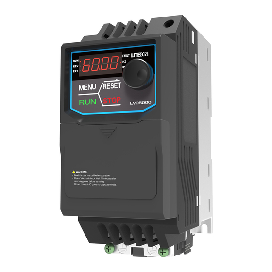
Chapter 2│Product 2.1 Component Names A – Heatsink D – Conduit bracket B – Cooling fan E – RJ45 port C – Fan guard F – Keypad 2.2 Receiving Checklist Check the following when receiving the drive: Is the packaging box in good condition? Any damage or damp ? If so, contact the distributor or local Lite-On representative. -
Page 11: Nameplate
2.3 Nameplate Model Number Applicable motor rating Input power supply Output power supply 2.4 Model Number Definition 6000 Version: Keypad Type: Filter: Product Series: S: Standard E: LED □ : No Filter EVO: Lite-On AC Drive F: Filter Built-In Series Name Enclosure: 20: IP20 Power Ratings:... -
Page 12: Power Ratings
2.5 Power Ratings 200V Class Single Phase Model No. EVO600021S 0.25 Max. Motor Capacity 0.75 Voltage (V) / Single Phases, 200 ~220 V, -15% ~ +20% , 50/60Hz Rated Frequency (Hz) Input Current(A) 13.5 Current(A) Output Rated 0 to 400 Hz Frequency(Hz) Output Carrier Frequency... -
Page 13: Common Specifications
400V Class Three Phase Model No. EVO600043S Max. Motor Capacity 0.75 Voltage (V) / Three Phases, 380 to 480 V, -15% to +10% , 50/60Hz Rated Frequency (Hz) Input Current(A) 12.9 Current(A) Output Rated 0 to 400 Hz Frequency(Hz) Output Carrier Frequency 2 to 12kHz (kHz) - Page 14 Over torque/torque shortage detection, multi-speed operation, acceleration/deceleration switching, instantaneous power failure restart, speed search, S-curve acceleration/deceleration, 3-wire sequential control, motor parameter automatic detection, cooling fan ON/OFF Parameter Function function, sliding Differential compensation, torque compensation, frequency jump, frequency command upper and lower limit setting, DC braking at start/stop, PID control, fault retry, automatic voltage adjustment.
-
Page 15: Product Dimensions
2.7 Product Dimensions Frame Size 1 200V: EVO600021S0D2E20F, EVO600021S0D4E20F, EVO600021SD75E20F, EVO600023S0D2E20, EVO600023S0D4E20, EVO600023SD75E20, EVO600023S1D5E20 400V: EVO600043S0D4E20F, EVO600043SD75E20F, EVO600043S1D5E20F Frame Size 2 200V: EVO600021S1D5E20F, EVO600021S2D2E20F, EVO600023S2D2E20, EVO600023S3D7E20 400V: EVO600043S2D2E20F, EVO600043S3D7E20F Frame Size 1 Frame Size 2 Unit: mm/inch Frame Φ Series 72[2.83] 59[2.32] 174.2[6.86] 151.6[5.97] 135.6[5.34]... -
Page 16: Accessories
2.8 Accessories 2.8.1 Accessories EVO6000 Series Accessories Name Model Name Description Allows parameter uploads/downloads and Copy Uint EVO-Kit-CU comparison Connects AC drive terminal DC+, DC- to significantly Braking unit EVO6-DBU-4 □□□ improve braking.Please ensure braking resistor is properly installed.(□□□ indicates 1D5 or 3D7 model ) -
Page 17: Installing Input Fuses
2.8.2 Installing Input Fuses Installing fuses on the drive input side is recommended to prevent internal short circuit. Select the suitable fuses below or the branch circuit protection in compliance with local electrician regulations. Line Fuse Three Phase 400V Model Input Current I (A) I (A) Bussmann P/N... -
Page 18: Chapter 3│Drive Installation
Chapter 3│Drive Installation 3.1 Installation Environment To ensure the optimum drive performance, install the AC drive in a proper environment specified below. Environment Conditions Area of Use Indoors -10°C to +50°C (IP20 enclosure) Do not install the drive in environments with wide temperature fluctuations ... -
Page 19: Installation Direction And Spacing
3.2 Installation Direction and Spacing 3.2.1 Installation Direction Install the AC drive upright for better cooling. c. Transverse installation b. Horizontal installation a. Upright installation Figure 3.1 Installation Direction 3.2.2 Installation Spacing Install the AC drive as illustrated below to ensure the required space for airflow and wiring. Figure Installation Spacing... -
Page 20: Keypad And Terminal Cover Installation
3.3 Keypad and Terminal Cover Installation It is not necessary to remove the keypad before wiring. You just need to loosen the terminal cover screw and remove the terminal cover. After wiring, affix the terminal cover back in position and tighten the screw. For wiring instructions and screw tightening torque please refer to Chapter 4. -
Page 21: Wiring Protection
3.4 Wiring Protection 3.4.1 Drive and Input Cable Protection for Short-Circuit Situations Protect the drive and input power cable by using fuse in case potential short-circuit situations cause overheat. Please refer to the following figure for proper wiring. Input cables Fuse Motor Figure 3.4 Fuse Installation... -
Page 22: Chapter 4│Wiring
Chapter 4│Wiring 4.1 Wiring Safety Danger Turn off all the power to the equipment before wiring. Wiring during power on could cause electrical shocks to personnel. Allow only qualified personnel for installation, wiring, repairing and parts replacement. Capacitors in the drive may still be charged for a short time after shutting off the power. Wait for the amount of time specified on the drive before any maintenance. -
Page 23: Main Circuit
4.2 Main Circuit Ensure the Stall Prevention function is off when using a braking unit ... -
Page 24: Main Circuit Terminal
4.2.1 Main Circuit Terminal Braking Unit (option) MCCB MC R/L 1 U/T 1 S/L 2 V/T 2 T/L 3 W/T 3 Fast Acting Fuse Table 4.2.1 Main Circuit Terminals Terminal Name Terminal Description R/L1, S/L2, T/L3 Power input terminal U/T1, V/T2, W/T3 Power output terminal +, - Braking unit terminal. - Page 25 and W respectively. Ensure the motor and drive terminals are in same phase sequence or the motor will rotate reversely. Do not connect power cable to output terminals of the drive. Failure to comply could cause drive damage and a fire. 4.2.2.3 Braking Unit Terminal: If the drive is used in a high-frequency or heavy duty application which requires frequent ...
-
Page 26: Main Circuit Cable Size And Tightening Torque
Follow the instructions below to remove the jumper if an even lower current leakage to a even lower level. Removing the jumper may increase the signal interference. 1. Front right corner of the machine, remove the screw using a screwdriver. 2. - Page 27 2. Terminal + and - are only for connecting DC reactor and braking resistor options. Do not connect it to other devices. 3. Consider the amount of voltage drop when selecting cable sizes. Increase the cable size when the voltage drop exceeds 2% of the motor rated voltage. The amount of voltage drop can be calculated using the following formula: Line drop voltage (V) = 3 ×...
-
Page 28: Control Circuit
4.3 Control Circuit RJ45 port can be connected to the built-in RS-485 communication or option communication cards (options cards are under development) Multi-function analog input S1 to S6 can be switched between Sink (NPN) mode and Source (PNP) mode. The default setting is NPN mode. DIP switch A1 is used to set the analog input type as voltage or current. -
Page 29: Control Circuit Terminals
4.3.1 Control Circuit Terminals 4.3.1.1 Input Terminals Table 4.3.1.1 Control Circuit Input Terminal Terminal Terminal Type Terminal Name Terminal Description Code Digital input terminal 1 (forward/stop) Digital input terminal 2 (reverse/stop) Photocoupler, 24 V, 8 mA. Digital input terminal 3 (external fault Use NPN/PNP switch to select multi-function digital input Digital input terminal 4 (fault reset) -
Page 30: Control Circuit Wiring
The ground terminal for control Ground terminal signals to avoid interference. Use shielded cables only. Common terminal for analog signals 4.3.1.2 Output Terminals Table 4.3.1.2 Control Circuit Output Terminals Terminal Terminal Type Terminal Name Terminal Description Code Relay 1 normal open Relay output Multi-Function DC 30 V, 1 A... -
Page 31: Control Circuit Cable Size And Tightening Torque
4.3.3 Control Circuit Cable Size and Tightening Torque Select the cable according to Table 4.3.3.1. Use crimp ferrules on the cable ends for simpler and more reliable wiring. Table 4.3.3.1 Cable Size and Tightening Torque Bare Cable Ferrule-Type Terminal Suggested Applicable Suggested Applicable... -
Page 32: I/O Connections
4.4 I/O Connections 4.4.1 NPN and PNP Mode Selection Use Sink/Source DIP switch on the control board to set NPN/PNP (Sink/ Source) mode for multi- function digital inputs S1 to S6. (Default: NPN mode) Figure 4.4.1 NPN/PNP (Sink/Source) DIP Switch... - Page 33 4.4.2 Terminal A1 Voltage/Current Input Selection Select voltage or current input at terminal A1 To select current as the input type, set DIP switch A1 to I and set parameter E3-00 to 0 (0 to 20 mA) or 1 (4 to 20 mA). To select voltage as the input type, set DIP switch A1 to V and set parameter E3-00 to 2 (0 ...
-
Page 34: Wiring Checklist
4.5 Wiring Checklist Table 4.6 Wiring Checklist □ Item Page Power Supply Voltage and Output Voltage □ 1 Power supply voltage is within the voltage range of specified drive input. □ 2 The motor voltage matches the drive output specifications. □... -
Page 35: Chapter 5│Keypad And Parameters
Chapter 5│Keypad and Parameters 5.1 Check before Operation Make sure the main circuit is properly wired. R/L1, S/L2 and T/L3 are power input terminals which cannot be mixed with U/T1, V/T2, W/T3. Failure to comply could cause damage to the AC drive. Make sure the ground terminal is properly wired. -
Page 36: Keypad
5.3 Keypad Use the keypad to enter RUN and STOP commands, display data, fault, alarm and set parameters. 5.3.1 Keys and Displays Figure 5.1.1 Keypad... - Page 37 Table 5.1.1 Keypad Keys and Displays Display Name Function Enters or exits the parameter group MENU Key Switches the displayed menu RUN Key Forward/reverse selection STOP Key Stops the drive. Refer to Table 5.1.2.2 Moves the cursor to the right RESET Key Resets the drive to clear a fault situation Press it as “...
-
Page 38: Keypad Display
5.1.2 Keypad Display 5.1.2.1 LED Display Table 5.1.2.1 LED Display Number Number Number Number /Letter /Letter /Letter /Letter Display Display Display Display... - Page 39 5.1.2.2 LED Indication Table 5.1.2.2 LED Indication Indicator Light Blinking Drive in deceleration Output frequency Drive in operation Drive not in operation below the minimum frequency Rotating reversely Allows Run commands only from a remote source During fault Normal operation Displaying output frequency...
-
Page 40: Keypad Programming
5.1.3 Keypad Programming Keypad Display Menu Structure A. Standard setting mode: Press MENU to switch among monitor group, A1-00 parameter group and A2-00 user-defined parameter group. Press ENTER, MENU, Non- slip setting dial, and RESET to monitor and edit settings. B. -
Page 41: Parameter List
5.4 Parameter List Name Description Setting Range Parameter Group A, Initialization A1: Basic Settings Selects access level ( edit /view) 0: View Only Access to only parameter A1-01. A1-01 Access Level 1: User-Defined Parameter Access Default∶ 2 <4> Selection Access to only parameter A1-01 and A2-00 to Range: 0, 1, 2 A2-15. - Page 42 Name Description Setting Range Parameter 3638: Resets 3-Wire Sequence / 60Hz / 380V 3641: Resets 3-Wire Sequence / 60Hz / 415V 3644: Resets 3-Wire Sequence / 60Hz / 440V 3646: Resets 3-Wire Sequence / 60Hz / 460V Set password to parameter A1-05 and enter the A1-04 Password password to parameter A1-04 to unlock it.
- Page 43 Name Description Setting Range Parameter 0: Reverse Rotation Enabled Drive accepts a run command of both Reverse Rotation forward and reverse directions Default: 0 b1-03 Selection 1: Reverse Rotation disabled Range: 0, 1 Drive can accept only run command of forward direction 0: Ignore Active Run Command at the New Source...
- Page 44 Name Description Setting Range Parameter Local/ Remote 0 ∶Disabled Default∶ 0 b1-12 switching Enable 1 ∶Enabled Range: 0, 1 during Operating Forward and 0 ∶Disabled Default∶ 0 b1-13 Reverse Selection 1 ∶Enabled Range: 0, 1 from Keypad b2: DC Braking Zero Speed Sets the start frequency for Zero Speed Holding Default∶...
- Page 45 Name Description Setting Range Parameter In order to reduce the speed of search output current by the V / f curve calculated by Default: 100% b3-05 Search speed in V / multiplying the voltage set value b3-05 by Min.: 10 % <7>...
- Page 46 Name Description Setting Range Parameter Default∶ 100.0% b5-05 Sets the maximum output from PID control as a PID Output Limit Min.: 0.0% <4> percentage of the maximum frequency. Max.: 100.0% Sets the PID bias voltage adjustment as a Default∶ 0.0% b5-06 PID Bias Voltage percentage of the maximum frequency to add...
- Page 47 Name Description Setting Range Parameter Sets the PID feedback time used for detection. Default∶ 1.0 s PID Feedback Low When the PID feedback falls below the level set b5-13 Min.: 0.0 s Detection Time to b5-12 for longer than this time, PID feedback Max.: 25.5 s loss will be detected.
- Page 48 Name Description Setting Range Parameter Sets the number of decimal places to display. 0 ∶ No Decimal Places Determined by b5-19 PID Target Display b5-25 1 ∶ 1 Decimal Place Min.: 0 Digits 2 ∶ 2 Decimal Places Max.: 3 3 ∶...
- Page 49 Name Description Setting Range Parameter Max.: 6000 s Default: 10.0 s Sets the time to decelerate from Jog Frequency C1-12 Jog Dec. Time Min.: 0.0 s Command (L1-16) to 0 Hz. Max.: 6000 s C2: S-Curve Characteristics S-Curve Default∶ 0.00 s C2-00 Characteristic at Min.: 0.00 s...
- Page 50 Name Description Setting Range Parameter 0: Determined by C6-01 to C6-03 Max.: 12 1: Retain 2: 2.0 kHz 3: 3.0 kHz 4: 4.0 kHz 5: 5.0 kHz 6: 6.0 kHz 7: 7.0 kHz 8: 8.0 kHz 9: 9.0 kHz 10: 10.0 kHz 11: 11.0 kHz 12: 12.0 kHz C7:SVVC (Sensorless Voltage Vector Control)
- Page 51 Name Description Setting Range Parameter Default: 25.00Hz L1-06 Frequency Min.: 0.00Hz <4> Command 7 Max.: <5> Default: 30.00Hz L1-07 Frequency Min.: 0.00Hz <4> Command 8 Max.: <5> Default: 35.00Hz L1-08 Frequency Min.: 0.00Hz <4> Command 9 Max.: <5> Default: 40.00Hz L1-09 Frequency Min.: 0.00Hz...
- Page 52 Name Description Setting Range Parameter L3: Jump Frequency Sets the Jump frequency range to avoid operation at the speed causing resonance in the L3-00 Jump Frequency 1 machinery. Default: 0.0 Hz Set L3-00, L3-01 and L3-03 to 0.0 Hz to disable Min.: 0.0 Hz Jump frequency.
- Page 53 Name Description Setting Range Parameter Group d, Motor Parameters d1: V/F Characteristics Sets the input voltage of the drive. Always set the input voltage of the drive (not Default : A1-03 Input Voltage motor) to this parameter d1-00 (input voltage) d1-00 Min.: 155 V Setting...
- Page 54 Name Description Setting Range Parameter Default: <1> Middle Output d1-06 Min.: 0.0 Hz Frequency Max.: Defined by d1-02 Default: <1> Middle Output d1-07 Min.: 0.0 V Frequency Voltage Max.: 255.0 V <3> Default: <1> Minimum Output d1-08 Min.: 0.0 Hz Frequency When d1-01 ≦...
- Page 55 Name Description Setting Range Parameter Default: o2-03 Sets the motor rated capacity. This will be set Motor Rated d2-10 Min.: 0.00 kW automatically during Auto-Tuning. (1HP = 0.746 Capacity Max.: 650.0kW Group E, Multi-Function Terminals E1: Multi-Function Digital Inputs 0 : 2-Wire Sequence Control (Forward/Stop) / 3- Default : 0 Terminal S1 E1-00...
- Page 56 Name Description Setting Range Parameter 65: DC Braking 69 : Drive Enabled (Note) 0xx/1xx are anti-logic E2: Multi-Function Digital Output 0 : During Run 1 : Zero Speed Holding 2 : Frequency (Speed) Agree 3 :User-Defined Frequency (Speed ) Agree 4 : Drive Ready 5 : Uv (Undervoltage) Detection 6 : During Baseblock...
- Page 57 Name Description Setting Range Parameter 49 : Brake Control (Desired frequency attained 52: Timer Input 100 to 149: 0 to 49 with Inverse Output E3: Multi-Function Analog Input 0: 0 to 20 mA Terminal A1 Signal 1: 4 to 20 mV Default: 2 E3-00 Level Selection...
- Page 58 Name Description Setting Range Parameter 8 : AI1 Input 10 : Soft Starter Output Frequency 12 : Retain <7> Default: 100.0 % E4-02 Terminal FM Sets the terminal FM monitor gain. Min.: -999.9 % <4> Monitor Gain Max.: 999.9 % Terminal FM Default: 0.0 % E4-03...
- Page 59 Name Description Setting Range Parameter Group P, Protections P1: Motor Protection Function 0 : Disabled (Motor Overload Protection Disabled) 1 : General-Purpose Motor (Standard Motor) Motor Protection Default: 1 P1-00 2 : Drive Dedicated Motor Function Selection Range: 0 to 3 (Constant Torque Range 1 : 10) 3 : Vector Motor (Constant Torque Range 1 : 100)
- Page 60 Name Description Setting Range Parameter regulation (AVR) 1 : AVR is enabled Range: 0, 1 Max.: 2 P3: Stall Prevention 0 ∶ Disabled 1 ∶ Enabled the value set in P3-01. Stall Prevention Acceleration stops when the output current Default: 1 P3-00 during exceeds the value set in P3-01.
- Page 61 Name Description Setting Range Parameter in P4-03. Sets the frequency command level at which the Frequency drive runs when detecting a frequency Default: 80% Command at P4-03 command loss and when L4-02 is set to 1. Sets Min.: 0.0 % Frequency the value as a percentage of the maximum Max.: 100.0 %...
- Page 62 Name Description Setting Range Parameter Enables or disables the input phase loss Input Phase Loss detection. Default: 0 P7-00 Protection 0 ∶ Disabled Range: 0, 1 1 ∶ Enabled Sets the output phase loss detection. Output Phase Loss 0 : Disabled Default: 1 P7-01 Protection...
- Page 63 Name Description Setting Range Parameter Group o, Keypad Function Settings o1: Display Setting 0 : Use units of 0.01 Hz Frequency 1 : Use units of 0.01% (100% as maximum output Default: 0 o1-00 Command frequency) Range: 0 to 2 Setting/Display Unit 2 : Use units of rpm o1-01...
- Page 64 Name Description Setting Range Parameter o4: Maintenance Settings Cumulative Sets the initial value by 1 hours to start keeping Default: 0 h o4-00 Operation track of cumulative operation time. Min.: 0 Time Setting Max.: 9999 Resets the data for U2-□□ (Fault Information) as these data will not be reset by A1-03 (Reset).
- Page 65 Name Description Setting Range Parameter Current (Stationary After the motor output power and rated current Min.: 0.0 A Auto-Tuning) are set in t1-02 and t1-04, this parameter will Max.: t1-04( Max ∶ 0 to automatically display the no-load current of a 2999.9) standard motor.
- Page 67 Group F, Optional Function Group F1: Pump function Parameter Name Description Unit Default: 10.0 According to the pressure sensor specification Min.: 0.0 User pressure sensor F1-00 (max. feedback voltage or pressure value Max.: 10.0 specification setting corresponding to feedback current) Unit: 0.1bar (kg/cm2) In the switch mode, the inverter automatically...
- Page 68 When the inverter is in the standby (sleep) state, when the pressure drops to the recovery level, Default: 0.3 the inverter starts and enters the PID control Min.: 0.0 PID control recovery F1-07 mode. Max.: 10.0 level setting Recovery level: Set pressure (SV) F1-07 set value. Unit: 0.1bar *When the set value is greater than the target (kg/cm2)
- Page 69 2 ∶ Sensorloess Voltage Vector Control (SVVC ) (Open-Loop) Frequency Displays the frequency command. (Display units U1-01 Command are defined by o1-00) Displays the output frequency. (Display units are U1-02 Output Frequency defined by o1-00) U1-03 Output Current Displays output current. 0.01A U1-04 Motor Speed...
- Page 70 software version U2: Fault Information U2-00 Current Fault Displays the current fault. U2-01 Most Recent Fault Displays the first most recent fault. Most Recent U2-02 Displays the second most recent fault. Fault U2-03 Most Recent Fault Displays the third most recent fault. U2-04 Most Recent Fault Displays the fourth most recent fault.
- Page 71 Most Recent most recent fault. Fault Output Current at Displays the output current at the second most U2-21 Most Recent 0.01A recent fault. Fault 2 Motor Speed at 2 Displays the motor speed at the second most U2-22 0.1 rpm Most Recent Fault recent fault.
- Page 72 Keeping track of time from run or power up is determined by o4-01. The maximum number displayed is 9999, after which the value will be counted from 0. Lights all segments of the LED to verify that the U3-07 LED Check display is working properly U3-10...
- Page 73 the maximum output frequency. Displays the PID output value as a percentage of U4-02 PID Output 0.01% the maximum output frequency. Displays the PID target value as a percentage of U4-03 PID Target 0.01% the maximum output frequency. PID Differential Displays the difference of both feedback values U4-04 0.01%...
- Page 74 <1> The default is determined by the drive capacity and control method. <2> Refer to user manual for details. http://www.liteon-ia.com.tw/ENG/download.php <3> Double the value for 440V class AC drives. <4> The parameter can be set during run. <5> The upper limit is determined by d1-02 and L2-00 settings.
-
Page 75: Chapter 6│Troubleshooting
Chapter 6│Troubleshooting 6.1 Alarm and Fault Displays Table 6.1 Alarm and Fault Displays, Causes, and Possible Solutions Keypad Fault Name Cause Possible Solution Display Retain 1. Remove the cause of the external fault then reset the multi-function 1. An external input. - Page 76 Keypad Fault Name Cause Possible Solution Display feedback input the PID feedback circuit falls below the level set to b5-12 for longer than the time set to b5-13. 1.Check the temperature surrounding the drive a. Improve the air flow inside the enclosure 1.
- Page 77 Keypad Fault Name Cause Possible Solution Display exceeded the torque level set to P6-01 for longer than the time set to P6-02 1. Install a DC link choke Voltage surge can result from a thyristor convertor and phase advancing capacitor using the same input power supply 1.
- Page 78 Keypad Fault Name Cause Possible Solution Display are weakened. contactor if there is no ( 350 V when d1- 5. The contactor or problem with the power 01<400 ) relay on the soft- supply charge bypass 4&5. Turn on and turn circuit is damaged off the power to see if any problem occurs...
- Page 79 Keypad Fault Name Cause Possible Solution Display Drive current 2. Deceleration and rating exceeded the level acceleration times 2. Calculate the torque of over current are too short required during warning (150% of 3.The drive is acceleration and the the rated current) attempting to run a inertia motor greater than...
- Page 80 Keypad Fault Name Cause Possible Solution Display emergency stop function turned on (P2-11) P2-11, or adjust P2-06 before the power off, settings Level when the DC bus 2. Confirm the multi- voltage is lower than function contact input P2-06 function set and terminal Multi-function status contact input is set to...
- Page 81 Keypad Fault Name Cause Possible Solution Display level set to b5-12 for longer than the time set to b5-13. 1.Check the temperature surrounding the drive 1. Ambient a. Improve the air flow inside the enclosure temperature is too Heatsink Overheat panel high b.
- Page 82 Keypad Fault Name Cause Possible Solution Display overvoltage output short circuit 2. Check the motor power cable, relay detection level 3. Ground fault in terminals and motor terminal box 1.200 V class: 410 the output circuit 3. Correct grounding shorts and reapply causes the DC bus power 2.400 V class: 820...
- Page 83 Keypad Fault Name Cause Possible Solution Display external baseblock input terminals (S1 signal to S6) Drive Overheat Warning 1. Search the device which caused the An overheat overheat warning. Remove the cause of the Drive Overheat warning in the drive problem.
- Page 84 Keypad Fault Name Cause Possible Solution Display Simulation A2 1. Simulation A2 1. Check the simulation signal wiring 2. Check the E3-10 parameter settings input signal is lost input signal is lost 1. Emergency stop is turned on (P2-11) before the power off, when the DC bus 1.
-
Page 85: Fault Detection
6.2 Fault Detection Table 6.2 Fault Displays, Causes, and Possible Solution Keypad Fault Name Cause Possible Solution Display Output power cable is Check and replace output power Ground Fault damaged cable 1. Increase the deceleration time 1. Regenerative energy is settings (C1-01 and C1-03) flowing from the motor into »Install a braking unit... - Page 86 Keypad Fault Name Cause Possible Solution Display 12. Electrical signal 7. Check the wiring of the interference causes the drive braking resistor and braking unit malfunction »Correct the wiring 13. Incorrect inertia setting 8. Tighten the terminal or of the load replace the damaged cable 14.Motor hunting occurs 9.
- Page 87 Keypad Fault Name Cause Possible Solution Display 8. Check the ratios between the 9. Excessive torque frequency and voltage set by compensation V/F. 10. Electrical signal 9. Adjust d1-02 to d1-11 (or d1- interference causes drive 13 to d1-22 for motor 2) malfunction 10.Check the amount of torque 11.
- Page 88 Keypad Fault Name Cause Possible Solution Display heat 2. Measure the output current a. Reduce the load b. Lower setting in C6-00 ( Carrier Frequency Option ) 3.Replace the cooling fan 1. Check the load, acceleration / deceleration time and cycle time a.
- Page 89 Keypad Fault Name Cause Possible Solution Display 9. The electrical thermal current protection characteristics do » Set d2-00 (Motor Rated not match the motor Current ) according to the motor overload characteristics. nameplate 10. The electrical thermal 7. Confirm the rated frequency relay operates at the wrong showed on the motor nameplate level...
- Page 90 Keypad Fault Name Cause Possible Solution Display 7. Speed Search related » Set a lower value to C6-00 parameters are set (Carrier Frequency) incorrectly 6. Check the torque 8. Power supply phase loss compensation causes output current » Set a lower value to C3-00 oscillation (Torque Compensation Gain) until the current is decreased...
- Page 91 Keypad Fault Name Cause Possible Solution Display to see if any problem occurs a. Replace either the entire drive or the control board if the problem continues to occur. Contact the local distributor for more information. Retain 1. Check wiring for errors in the main circuit drive input power »Correct wiring 2.
- Page 92 Keypad Fault Name Cause Possible Solution Display 1. Incorrect parameter settings 1. Reset b5-22 and b5-23 2. Incorrect PID feedback PID Feedback High 2. Correct the wiring wiring 3. Check the sensor 3. Feedback sensor malfunction 1. Incorrect parameter settings 1.
-
Page 93: Operation Errors
6.3 Operation Errors Table 6.3 Error Displays, Causes, and Possible Solutions Keypad Error Name Cause Possible Solution Display 1. Set the parameters to the Parameter Range Parameters are set outside of oE02 proper values Setting Error the possible setting range 2. -
Page 94: Auto-Tuning Fault Detection
Keypad Error Name Cause Possible Solution Display Incorrect d1-02, d1- 04, d1-06, d1-08, d1-09 settings 1. Contradictory settings · C6-03 (Carrier Frequency Proportional Gain)>6 · C6-02 (Minimum Carrier Frequency)> C6-01 Carrier Frequency (Maximum Carrier oE11 Correct the parameter setting. Setting Error Frequency) Note: If C6-03 ≤... - Page 95 Make sure the data entered to t1-05 and t1-07 is the same as the t5-05 and t1-07 setting TF07 Motor Data Error information showed on the motor incorrect nameplate. Reset the parameters.
- Page 96 Edit Date Edit Date Parameter Parameter A1-00 b3-04 A1-01 b3-05 A1-02 b5-00 A1-03 b5-01 A1-04 b5-02 A1-05 b5-03 A2-00 b5-04 A2-01 b5-05 A2-02 b5-06 A2-03 b5-07 A2-04 b5-08 A2-05 b5-09 A2-06 b5-10 A2-07 b5-11 A2-08 b5-12 A2-09 b5-13 A2-10 b5-14 A2-11 b5-15 A2-12...
- Page 97 Edit Date Edit Date Parameter Parameter C2-03 d1-05 C3-00 d1-06 C5-00 d1-07 C5-01 d1-08 C6-00 d1-09 C6-01 d2-00 C6-02 d2-01 C6-03 d2-02 L1-00 d2-03 L1-01 d2-04 L1-02 E1-00 L1-03 E1-01 L1-04 E1-02 L1-05 E1-03 L1-06 E1-04 L1-07 E1-05 L1-08 E2-00 L1-09 E3-00 L1-10...
- Page 98 Edit Date Edit Date Parameter Parameter P2-02 o4-01 P2-03 o4-06 P2-05 o4-07 P3-00 o4-08 P3-01 t1-02 P3-02 t1-03 P3-03 t1-04 P3-05 t1-05 P3-06 t1-06 P3-07 t1-07 P3-08 t1-10 P3-11 t1-12 P4-00 P4-01 P4-02 P4-03 P4-04 P5-00 P5-01 P5-02 P6-00 P6-01 P6-02 P7-00 P7-01...
- Page 99 Appendix UL Descriotion 1) “Maximum surrounding air temperature rating of 50ºC” 2) “The drive is suitable for use in a circuit capable of delivering not more than 5,000 rms symmetrical amperes, Maximum, 220 V for 200 V three-phase, 240 V for 200 V single-phase, 480 V for 400 V three-phase.
- Page 100 1) COURANT NOMINAL DE COURT-CIRCUIT, 5000 A SYMÉTRIQUES EFF. MAXIMUM, 220 V POUR 200 V TRIPHASÉ, 240 V POUR 200 V MONOPHASÉ, 480 V POUR 400 V TRIPHASÉ. 2) CONVIENT AUX CIRCUITS NON SUSCEPTIBLES DE DE DÉLIVRER PLUS DE 5000 AMPÉRES SYMÉTRIQUES EFF. MAXIMUM, 220 V POUR 200 V TRIPHASÉ, 240 V POUR 200 V MONOPHASÉ, 480 V POUR 400 V TRIPHASÉ.
- Page 101 Model No. Branch Circuit Fuses EVO600023S0D2 Class RK5, rated 240 V ac or higher, 5 A EVO600023S0D4 EVO600023SD75 Class RK5, rated 240 V ac or higher, 10 A EVO600023S1D5 Class RK5, rated 240 V ac or higher, 15 A EVO600023S2D2 Class RK5, rated 240 V ac or higher, 20 A EVO600023S3D7 Class RK5, rated 240 V ac or higher, 30 A...
- Page 102 EVO6000QMEN1810V01...
Need help?
Do you have a question about the EVO6000 Series and is the answer not in the manual?
Questions and answers