Honeywell MicroniK 200 R7426A Installation & Start-Up Instructions
Hide thumbs
Also See for MicroniK 200 R7426A:
- Installation & start-up instructions (20 pages) ,
- Specification data (9 pages)
Advertisement
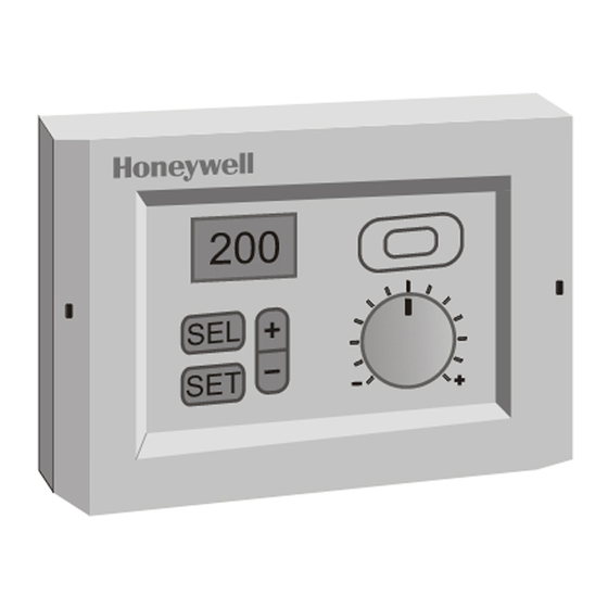
MicroniK 200
Fig. 1. Temperature Controller
GENERAL
This document provides instructions and procedures for
installing and starting up the Micronik 200 R7426A,B,C
controllers. No special tools are required for mounting and
installation. The user interface and LC display allows
accurate and easy parameter setting and output adjustment.
7157 588
TEMPERATURE CONTROLLER
INSTALLATION & START-UP INSTRUCTIONS
BEFORE INSTALLATION NOTE
•
Visually inspect equipment for shipping damage.
Report any damage to the appropriate Honeywell
representative.
•
Refer to job drawings for specific installation
information and mounting location.
•
Verify the controllers will be adequately separated
from the main power supply, relays or other
equipment which can possibly generate electro-
magnetic interference.
•
Verify that the ambient temperature and the humidity
at the controllers will not exceed 0...50 ° ° ° ° C (0...122 ° ° ° ° F)
and 5 to 95% rh.
•
Use shielded wiring in areas with high EMI.
•
All wiring should be separated from power lines by at
least 150 mm (6'').
•
Do not install controllers near frequency converters
or other high-frequency sources.
MOUNTING
The controllers can be mounted in an electric cabinet or an
other suitable enclosure. They are suitable for back panel,
DIN rail, wall or front panel mounting with an additional
available front panel mounting frame. The mounting
sequence of each is illustrated in the mounting instruction
sheet EN1B-0205GE51 supplied with the controllers.
Dimensions and panel cut-out are shown in section
"Dimensions and Mounting" on page 2.
If the compensation sensor signal (T3) is received from
another controller (parallel connection of compensation
sensor inputs), the jumper W303 must be cut before
mounting the controller (see Fig. 3 on page 3). This
disconnects the sensor from the internal power supply.
HONEYWELL
R7426A,B,C
EN1B-0206GE51 R0602
Advertisement
Table of Contents

Related Manuals for Honeywell MicroniK 200 R7426A


Summary of Contents for Honeywell MicroniK 200 R7426A
- Page 1 This document provides instructions and procedures for The controllers can be mounted in an electric cabinet or an installing and starting up the Micronik 200 R7426A,B,C other suitable enclosure. They are suitable for back panel, controllers. No special tools are required for mounting and DIN rail, wall or front panel mounting with an additional installation.
-
Page 2: Dimensions And Mounting
R7426A,B.C Temperature Controller DIMENSIONS AND MOUNTING Honeywell All dimensions in mm. 198 +/-0.3 121 +/- 0.3 170 +/-0.3 (when mounting on DIN rail) approx. 45 x 35 (cut-out for cables) 180 +/-0.2 wall mounting front panel mounting Fig. 2. Dimensions and mounting... -
Page 3: Power Supply And Grounding
R7426A,B.C Temperature Controller POWER SUPPLY AND GROUNDING 1. Refer to job drawings and verify correct supply voltage to 3. Connect transformers 24 Vac secondary to the controller transformer (230 Vac) and controller (24 Vac). terminals 18 and 19. Connect one conductor to terminal 2. - Page 4 R7426A,B.C Temperature Controller CONTROL / CONFIGURATION PARAMETERS The controller includes two groups of settings (A and B) for control and configuration parameters that are automatically selected during programming. For R7426A and parameter Ctrltyp = Lo or R7426B,C, setting A is selected. For R7426A and parameter Ctrltyp = Hi, setting B is selected.
-
Page 5: Configuration Settings
R7426A,B.C Temperature Controller CONFIGURATION SETTINGS Control Point / Setpoint Adjustment CPATYP (C.05) The controllers R7426A,B are supplied with unconfigured outputs to avoid damage of installed final control devices by The control point or setpoint can be adjusted via the internal supply of unallowed output signals if the controller power or external potentiometer connected to the CPA/SPA input. -
Page 6: Parameter Settings And Adjustment
R7426A,B.C Temperature Controller Multistage ON/OFF Function YMode (C.11) up reset the controller detects automatically the type of sensor, which is connected to the main temperature input T1. In the case of the R7426B controller with three floating For a correct auto detection, it is necessary that the outputs, several ON/OFF sequence control functions can be measured temperature is in the specified range (see Table selected by the configuration parameter YMode (see Table... - Page 7 R7426A,B.C Temperature Controller known. This is the maximum air temperature increase Table 7. Throttling range and reset time reference produced by the heating coil or decrease of a cooling coil if Application Sens. tr1 tr2 the control valve is fully open. R7426A Controller The proportional band X for discharge air control can be...
- Page 8 R7426A,B.C Temperature Controller of valve position) and the instant when the resulting change Table 8. Calculation of summer/winter compensation in the output signal reaches a specified fraction of its final Outdoor air Control Room temp. Throttling steady-state value, either before overshoot or in the absence temp.
- Page 9 R7426A,B.C Temperature Controller open position to which an outdoor air damper actuator can be Table 9. Control point reference and calculation driven from the controller. In mixed air damper applications it Application CTRP1 CTRP2 CTRPC CTRPH maintains the minimum outdoor air damper setting, even Main Temperature Control though the temperature input condition calls for a fully closed Limit Control...
- Page 10 R7426A,B.C Temperature Controller OPERATING OVERVIEW Engineering units Display and Operation Elements The MicroniK 200 user interface is shown in Fig. 6. Changing Operating Modes Fig. 7 shows the five operating modes. After power-up the controller version is displayed and the controller enters the standard display mode (Fig.
- Page 11 R7426A,B.C Temperature Controller Main Temperature T1 alternates alternates alternates alternates after 1sec after 1sec after 1sec after 1sec Main Setpoint Output Y1 CTRP1 Limitation/ Cascade Temperature T2 alternates alternates alternates alternates after 1sec after 1sec after 1sec after 1sec Submaster/Limit Output Y2 Setpoint CTRP2 R7426B...
-
Page 12: Selecting Parameters
R7426A,B.C Temperature Controller Displaying Actual Values In the standard display mode one of ten actual values can be selected (Fig. 8). Pushing the SEL button toggles between the ten actual values. The output signal value is displayed as 0...100% value in correspondence with the nominal control range. - Page 13 R7426A,B.C Temperature Controller Selecting Output Values : Manual Override is active Space: Control Loop is active The output selection mode is used to select the output (see Fig. 11) for manual override adjustment. An activated manual override is indicated by a displayed F (fixed). Pushing the + or - button scrolls through the output list.
- Page 14 R7426A,B.C Temperature Controller Interpreting Error Messages (error handling) Different analog input errors can be identified by the controller. The defective analog input (T1, T2, T3 or X ) will be displayed in the standard display mode (see Fig. 13) after the corresponding value is selected.
-
Page 15: Adjustment Example
R7426A,B.C Temperature Controller Adjustment Example This example (Fig. 14) describes the adjustment of the compensation changeover point W (P03). comp Standard Display Mode Push simultaneously for appr. 2sec Parameter Selection Mode alternates alternates after 1sec after 1sec Parameter Adjustment Mode Push until needed value is displayed Parameter Selection Mode... - Page 16 R7426A,B.C Temperature Controller HONEYWELL Control Products Honeywell AG Böblinger Straße 17 D-71101 Schönaich Phone: (49) 7031 63701 Fax: (49) 7031 637493 http://europe.hbc.honeywell.com Subject to change without notice. Printed in Germany Manufacturing location certified to 7157 588 EN1B-0206GE51 R0602...
Need help?
Do you have a question about the MicroniK 200 R7426A and is the answer not in the manual?
Questions and answers