Wilo Control DrainAlarm Installation And Operating Instructions Manual
Hide thumbs
Also See for Control DrainAlarm:
- Installation and operating instructions manual (152 pages) ,
- Manual (20 pages)
Table of Contents
Advertisement
Quick Links
Pioneering for You
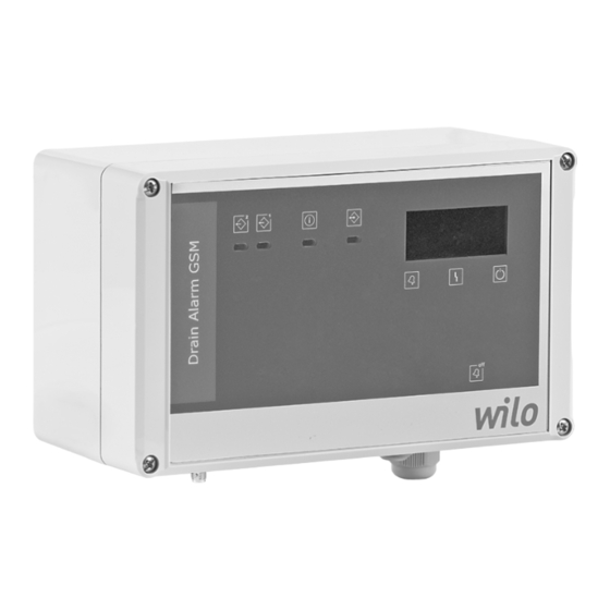
Wilo-Control DrainAlarm/-GSM
de Einbau- und Betriebsanleitung
en Installation and operating instructions
fr
Notice de montage et de mise en service
it
Istruzioni di montaggio, uso e manutenzione
nl
Inbouw- en bedieningsvoorschriften
da
Monterings- og driftsvejledning
no Monterings- og driftsveiledning
sv
Monterings- och skötselanvisning
fi
Asennus- ja käyttöohje
pl
Instrukcja montażu i obsługi
ru Инструкция по монтажу и эксплуатации
ro Instrucţiuni de montaj şi exploatare
2527912 Ed03-04/2016 WH
Advertisement
Table of Contents

Related Manuals for Wilo Control DrainAlarm

Summary of Contents for Wilo Control DrainAlarm
- Page 1 Pioneering for You Wilo-Control DrainAlarm/-GSM de Einbau- und Betriebsanleitung en Installation and operating instructions Notice de montage et de mise en service Istruzioni di montaggio, uso e manutenzione Inbouw- en bedieningsvoorschriften Monterings- og driftsvejledning no Monterings- og driftsveiledning Monterings- och skötselanvisning Asennus- ja käyttöohje...
- Page 2 Fig. 1: DrainAlarm A B C 1 2 3 4 5 PE N L1 12 V 1~230 V, 50/60 Hz Fig. 2. DrainAlarm GSM 27 26 25 24 23 22 21 20 19 18 17 16 15 14 GSM-Modul 27 26 25 24 23 22 21 20...
-
Page 3: Table Of Contents
Electrical connection Operation and function 6.1. Controls 6.2. Configuring the GSM module Commissioning 7.1. Connections 7.2. Operation in potentially explosive areas 7.3. Switch on the alarm switchgear 7.4. Conduct during operation Decommissioning/disposal 8.1. Disposal 8.2. Rechargeable battery Troubleshooting and possible solutions Installation and operating instructions Wilo-Control DrainAlarm/-GSM... -
Page 4: Introduction
1.4. Subject to change The manufacturer reserves the right to make technical modifications to systems or compo- nents. This operation and maintenance manual Danger symbol, for example, electrical current refers to the alarm switchgear indicated on the title page. Symbol for prohibited action, e.g. No entry! WILO SE 04-2016 V06 DIN A4... -
Page 5: General Safety Information
• Visual and audible alarm signalling of external alarm signal (collective fault or high water signals) Installation and operating instructions Wilo-Control DrainAlarm/-GSM... -
Page 6: Set-Up
13 GSM module: SMA connection for GSM antenna the switchgear. The alarm signal can be forwarded 14 GSM module: GSM modem to a remote control system via the alarm out- 15 GSM module: Mini USB connection puts, or signalled via external alarm signal. The alarm can be acknowledged directly on the alarm WILO SE 04-2016 V06 DIN A4... -
Page 7: Technical Data
Heat or dust can • Installation and operating instructions cause damage to electrical components! 3.9. Accessories • Following an extended period of storage, the alarm switchgear should be dusted before com- • Float switch for wastewater and sewage free of missioning. faeces Installation and operating instructions Wilo-Control DrainAlarm/-GSM... -
Page 8: Return Delivery
English INSTALLATION If condensate has formed, the Wilo customer cross-section used and the installation type se- service team must check that the individual lected, and whether the cable length is sufficient. components are working properly. Defective The power supply cables should not be installed components must be replaced immediately. -
Page 9: Electrical Connection
If an alarm is signalled, there is a DC voltage at the alarm output (DrainAlarm fig. 1, item 4/ DrainAlarm GSM fig. 2, item 4) for operating ex- DrainAlarm ternal alarm signals: 1x alarm input on the terminal strip (fig. 1, item 4): • Connected load: 12 VDC, max. 1 A • Terminal: 6 and 7 • Terminal 1: Plus (+) • The connection must be potential-free. • Terminal 2: Minus (-) • Contact type: Normally open contact • Contact type: Normally open contact Installation and operating instructions Wilo-Control DrainAlarm/-GSM... - Page 10 The wires must be connected to the terminal strip (fig. 1/2, item 4) as follows: 5.4.8. Connecting the GSM antenna (DrainAlarm GSM • Terminal “L”: Phase only) • Terminal “N”: Neutral conductor Connect and lay the GSM antenna to the SMA • Terminal “PE”: Earth bush (fig. 1, item 13). The antenna is self-adhe- WILO SE 04-2016 V06 DIN A4...
-
Page 11: Operation And Function
256 MB 512 MB Hard drive space 10 MB 10 MB LED is lit up: Mains voltage is present, Green CD-ROM Required for installation from CD battery is charging 1024 x 768, 1280 x 800 256 colours 32 bit USB standard* USB connection Mini-USB Mini-USB Installation and operating instructions Wilo-Control DrainAlarm/-GSM... -
Page 12: Commissioning
The signal transmitters on the digital inputs and shocks. Only operate the alarm switchgear the controls/components at the alarm outputs with the cover closed! (changeover contacts) are connected poten- tial-free. WILO SE 04-2016 V06 DIN A4... -
Page 13: Decommissioning/Disposal
9. Troubleshooting and possible solutions The LEDs indicate possible faults. BEWARE of moisture! Please contact Wilo customer service if trouble- Ingress of moisture will result in damage to shooting fails. Unsanctioned modifications to the alarm switchgear. During downtime, ob- the alarm switchgear are made at the operator's... - Page 16 WILO SE Nortkirchenstraße 100 44263 Dortmund Germany T +49 (0)231 4102-0 F +49 (0)231 4102-7363 wilo@wilo.com Pioneering for You www.wilo.com...
Need help?
Do you have a question about the Control DrainAlarm and is the answer not in the manual?
Questions and answers