
Related Manuals for Auto openers SO-1000F

Summary of Contents for Auto openers SO-1000F
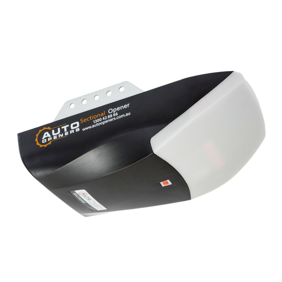
- Page 1 Sectional Opener To view our how to install video visit: www.autoopeners.com.au 1300 42 88 66 To view our how to install video visit: www.autoopeners.com.au...
-
Page 2: Table Of Contents
Table of Contents Installation Instructions ..........................4 Site Requirements ............................4 Setup Requirements ............................4 Installation (Steel Track) ..........................6 Installation (Sectional Steel Track) ....................... 7 Door Travel / Limit Settings ........................9 Travel limit setting ............................9 Remote Programming Instructions ......................9 Safety reverse force adjustment ......................... - Page 3 • If the power supply cord is damaged, it must be replaced by an Auto Openers Service Agent or suitably qualified person. • Connect the opener to a properly earthed general purpose 240V mains power outlet installed by a qualified electrical contractor.
-
Page 4: Installation Instructions
Installation Instructions SAFETY INSTRUCTIONS FOR INSTALLATION Not following the installation instructions can lead to serious injury or equipment failure. Ensure you follow the steps carefully to avoid complications. Site Requirements a. Look at the ceiling: i. Is it plastered? The opener is mounted to a perforated angle which MUST be securely fastened to a structural support. - Page 5 Referring to Fig. 1 for recommended installation 1) Track 4) Powerpoint / Power Cord 2) PE Safety Beams 5) Light Cover 3) Motor Powerhead Fig.3 Fig.2 Maintaining a minimum gap of 30mm from the top panel’s maximum height (Fig. 2). Make sure the track is horizontal and vertical to the shaft.
-
Page 6: Installation (Steel Track)
Installation (steel track) Fig. 6 1. Fix the wall bracket to the wall 2cm-10cm over the shaft or intermediate bracket (depending on the actual installation space). 2. Fix the steel track to the wall bracket with axis pin. (Fig. 6) 3. -
Page 7: Installation (Sectional Steel Track)
Installation (Steel Track) of 3 Piece Rail The middle rail The end rail The first sleeve Fig. 7 The top rail The middle rail The end rail The second sleeve The first sleeve Fig. 8 Fig. 9 To view our how to install video visit: www.autoopeners.com.au... - Page 8 Fig. 10 19MM Fig. 11 1. As per Fig.7, slide the end rail into the 1st sleeve & slide the middle rail into the 1st sleeve. 2. As per Fig.8, slide the 2nd sleeve to the other end of middle rail & slide the top rail into the 2nd sleeve. 3.
-
Page 9: Door Travel / Limit Settings
Door Travel / Limit Settings 1. Travel limit setting Press the ‘SET’ button and hold on until the LED displays figure ‘1’; then adjust the up limit by pressing ‘up’ button. Fine-tuning ‘up’ or ‘down’ button to determine the final up limit position then press t h e ‘set’ button. T he display will now change to ‘2’. -
Page 10: Auto-Close Setting (Optional)
4. Auto-close setting (Optional) Press the ‘UP’ button and hold on until the LED displays ‘-’. E v e r y t i m e y o u p ress t h e ‘UP’ button, the auto-close time will increase by 1 minute, the maximum time is 9 minutes. - Page 11 Optional Functions 1. The Operate interface available Add another Operate button to open or close the door. The photo beam interface available When connecting pulsed quantity control infrared sensor, wiring as per Fig.12. When infrared sensor is controlled by switch value, wiring as per Fig.13. Notice: Close the photo beam function when you don’t use photo beam sensors.
- Page 12 Fig. 13 To view our how to install video visit: www.autoopeners.com.au...
- Page 13 Fig. 14 Fig. 15 To view our how to install video visit: www.autoopeners.com.au...
-
Page 14: Packing List
Sectional Opener Instruction Manual Packing list Item Quantity Door opener Track ( incl. Clutch) Remote control Door bracket Wall bracket “U” bracket Hanging bracket Clutch cord Cord pendant Bent arm Straight arm Fixing kit To view our how to install video visit: www.autoopeners.com.au... -
Page 15: Optional And Additional Accessories
Sectional Opener Instruction Manual Optional & Additional Accessories To view our how to install video visit: www.autoopeners.com.au... - Page 16 •This Warranty is to be read in conjunction with the owner’s copy of the installation instruction manual. •In this warranty, ‘Auto Openers Representative’ means an entity authorized by Auto Openers to service Auto Openers products. Please check the Auto Openers website for details.
-
Page 17: Warranty Registration
(b) No additional warranty will apply for Products repaired during the relevant warranty period. (c) Where the Product is sold by any person other than Auto Openers, except for the warranty set out above, such person has no authority from Auto Openers to give any warranty or guarantee on Auto Opener’s behalf in addition to the warranty set out above. - Page 18 Sectional Opener Instruction Manual To view our how to install video visit: www.autoopeners.com.au...
Need help?
Do you have a question about the SO-1000F and is the answer not in the manual?
Questions and answers