
Subscribe to Our Youtube Channel
Related Manuals for Elsema Intelligent Swing iS400

Summary of Contents for Elsema Intelligent Swing iS400
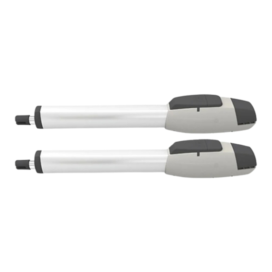
- Page 1 iS400 / iS400D / iS400Solar SWING GATE OPENER with LIMIT SWITCH USER MANUAL iS400/iS400D/iS400Solar SWING GATE OPENER MANUAL ...
-
Page 2: Table Of Contents
INDEX GENERAL SAFETY PRECAUTION ............P.1 INSTALLATION A. STANDARD INSTALLATION ..............P.2 B. INSTALLATION CHECK ...............P.3 C. REAR BRACKET INSTALLATION ............P.4 D. FRONT BRACKET INSTALLATION …………........P.4 E. MOTOR FIXING ..................P.5 F. WIRE CONNECTION ................P.5 G. EMERGENCY RELEASE ..............P.6 H. LIMIT SWITCH ADJUSTMENT .............P.6 TECHNICAL FEATURES A. -
Page 3: General Safety Precaution
11) Only operate the remote when you have the full view of the gate. ELSEMA PTY LTD shall not be liable for any injury, damage, or any claim to any person or property which may result from improper use or installation of this system. -
Page 4: Installation
1.2 STANDARD INSTALLATION A. STANDARD INSTALLATION 2 iS400/iS400D/iS400Solar SWING GATE OPENER MANUAL ... - Page 5 B. CHECKS BEFORE INSTALLATION Before proceeding with the installation check the following: 1) Check that the motor mounting position on the gate pillar can be done with the measurements in Figure 1 and Graph 1 2) Be sure that gate moves freely 3) There are no obstacles in the moving gate area 4) Hinges are properly positioned and greased 5) There should be no friction between the gate leaf’s...
- Page 6 C. INSTALLATION OF REAR BRACKET Step 1: Before securing the rear bracket to the pillar check the front bracket can be welded to a solid point on the gate leaf. Fully close the gate. Connect the rear and front brackets to the motor. ...
-
Page 7: Motor Fixing
E. MOTOR FIXING While the motor is disengaged, remove the wire cover and fix the rear bracket with the pin. The pin will slot into the hole with the threaded side up as shown in no.1. No screw is required to hold the pin in place. -
Page 8: Emergency Release
G. EMERGENCY RELEASE In case of power failure, slide the lid of the manual release chamber forward. Insert the key and turn clockwise to unlock, and then turn around the knob to release. Step1. Slide the lid of the release chamber forward Step2. -
Page 9: Technical Features
I. ELECTRICAL CONNECTION After successful motor installation, refer to the user manual of the control card for automatic operation setup. 1.3 TECHNICAL FEATURES: A. Technical Features: Motor Voltage 24Volts DC motor Gear Type Worm gear Max Absorbed Power 144 Watts Peak Thrust 4500N Nominal Thrust... -
Page 10: Maintenance
1.4 MAINTENANCE Maintenance should be performed at least every six months. If it is used in high traffic area, a more regular maintenance should be performed. Disconnect the power supply Clean and lubricate the screws, the pins and the hinge with grease. Check the fastening points are properly tightened. - Page 11 Solar kits Solar panels Backup batteries Photo electric beams Magnetic locks Wireless keypads Pre formed loop Visit www.elsema.com to see our full range of Gate and Door Automation products iS400/iS400D/iS400Solar SWING GATE OPENER MANUAL ...
- Page 12 iS400/iS400D/iS400Solar SWING GATE OPENER MANUAL ...
Need help?
Do you have a question about the Intelligent Swing iS400 and is the answer not in the manual?
Questions and answers