Table of Contents
Advertisement
Quick Links
Advertisement
Table of Contents

Related Manuals for Lighthouse REMOTE 2 Series


Summary of Contents for Lighthouse REMOTE 2 Series
- Page 3 Lighthouse Worldwide Solutions REMOTE 2012, 3012, 5012, 3102, 5102 Airborne Particle Counter Operating Manual...
- Page 4 Copyright © 2004-2008 by Lighthouse Worldwide Solutions. All rights reserved. No part of this document may be reproduced by any means except as permitted in writing by Lighthouse Worldwide Solutions. The information contained herein constitutes valuable trade secrets of Lighthouse Worldwide Solutions.
- Page 5 EU DECLARATION OF CONFORMITY Manufacturer’s Name Lighthouse Worldwide Solutions, Inc. Manufacturer’s Address: Lighthouse Worldwide Solutions, Inc. 1221 Disk Drive Medford, OR 97501 Declares that the product: Product Name: Remote Airborne Particle Counter Model Number(s): REMOTE 2012, 3012, 5012, 3102, 5102...
-
Page 7: Table Of Contents
Table of Contents About This Manual Text Conventions ........................ i Additional Help ........................i Chapter 1 General Safety Safety Considerations ....................1-1 Laser Safety Information ....................1-1 Electrostatic Safety Information ..................1-2 Chapter 2 Introduction Overview ........................2-1 Description ........................2-1 Accessories ........................ - Page 8 Lighthouse REMOTE 2012, 3012, 5012, 3102, 5102 Operating Manual DIP Switch Settings and Meanings ..............4-3 Procedure to Set DIP Switches ................4-3 Example Startup Echo, Reading DIP Switches: ........4-3 Connecting the Instrument to a Terminal ..............4-4 Power Up ........................4-6 Session Example ......................
- Page 9 Table of Contents Chapter 6 Maintenance Procedures Introduction ........................6-1 Safety ..........................6-1 Calibration ........................6-1 Purge Count Test ......................6-1 Fault Isolation ........................ 6-2 Appendix A Limited Warranty Limitation Of Warranties: ..................... A-1 Warranty Of Repairs After Initial Two (2) Year Warranty: ......... A-1 Index 248083201-1 Rev 6 t-iii...
- Page 10 Lighthouse REMOTE 2012, 3012, 5012, 3102, 5102 Operating Manual t-iv 248083201-1 Rev 6...
-
Page 11: About This Manual
About This Manual This manual describes the detailed operation and use of the Lighthouse REMOTE 2 Series Airborne Particle Counters. Text The following typefaces have the following meanings: Conventions Note: italics Represents information not to be typed A note appears in the sidebar to give extra or interpreted literally. - Page 12 Lighthouse REMOTE 2012, 3012, 5012, 3102, 5102 Operating Manual 248083201-1 Rev 6...
-
Page 13: Chapter 1 General Safety
General Safety Safety Warnings and cautions are used throughout this manual. Familiarize Considerations yourself with the meaning of a warning before operating the particle counter. All warnings will appear in the left margin of the page next to the subject or step to which it applies. Take extreme care when doing any procedures preceded by or containing a warning. -
Page 14: Electrostatic Safety Information
Lighthouse REMOTE 2012, 3012, 5012, 3102, 5102 Operating Manual Electrostatic Safety Information WARNING: Electrostatic discharge (ESD) can damage or destroy electronic Using a wrist-strap without an components. Therefore, all service or maintenance work should be isolation resistor will done at a static-safe work station. A static-safe work station can be... -
Page 15: Chapter 2 Introduction
Overview This operating manual introduces you to the Lighthouse REMOTE 2012, 3012, 5012, 3102, 5102 (REMOTE 2 Series) family of two- channel Airborne Particle Counters. Also included in this manual are instructions for inspecting, using, and maintaining the instrument. Any changes of instrument operation due to design changes are covered at the back of this manual. -
Page 16: Accessories
Pulses are counted and their amplitude is measured for particle sizing. The REMOTE 2 Series line of Airborne Particle counters was created for continuous operation 24 hours per day, 7 days per week. Using an external vacuum source, the instrument provides versatile mounting options and can be installed where space is at a premium. -
Page 17: Remote Specifications
14° F to 122° F (-10° C to 50° C) / Up to 98% Storage Temp/RH non-condensing Table 2-1 Specifications The manufacturer recommends that your Lighthouse instrument be calibrated annually by a Certified Lighthouse Service Provider to ensure that it continues to perform within specification. 248083201-1 Rev 6... - Page 18 Lighthouse REMOTE 2012, 3012, 5012, 3102, 5102 Operating Manual 248083201-1 Rev 6...
-
Page 19: Chapter 3 Getting Started
3. Seal container or carton securely. Mark "FRAGILE" and enter Return Merchandise Authorization (RMA) number in any unmarked corner. 4. Return to the address instructed by your Lighthouse representative. 248083201-1 Rev 6... -
Page 20: Interpreting The Indicators
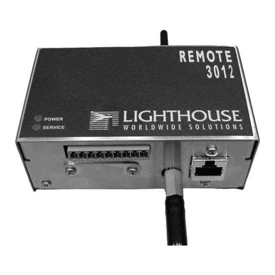
Lighthouse REMOTE 2012, 3012, 5012, 3102, 5102 Operating Manual Operation Interpreting the Indicators Both front-panel indicators have a specific meaning when illuminated. The figure below shows location of the indicators and gives a brief description of their meaning. POWER LIGHT (GREEN) -
Page 21: Connections
Getting Started Connections Inlet fitting Figure 3-2 Connections on Top of Instrument Programming Port for external vacuum Figure 3-3 Connections on Bottom Right of Instrument Figure 3-4 J10 Labeling (with Status feature on pin 5) 248083201-1 Rev 6... -
Page 22: Installation
Lighthouse REMOTE 2012, 3012, 5012, 3102, 5102 Operating Manual Figure 3-5 J10 Labeling (without Status feature on pin 5) Installation Your instrument(s) can be easily prepared for use by performing the steps below. Depending on the unit’s output, each instrument can be located up to 1000 feet (330 meters) from the counting device. -
Page 23: Installing An Isokinetic Probe
Getting Started 4. Attach tubing from external vacuum source to the barbed fitting on the bottom of the unit. Installing an An Isokinetic probe can be attached directly to the unit. Screw the probe directly onto the inlet. Isokinetic Probe Figure 3-8 Installing Probe Directly on Barb Data Port Connector J10 on the bottom of the instrument is used to communicate... - Page 24 Lighthouse REMOTE 2012, 3012, 5012, 3102, 5102 Operating Manual Table 3-2 J10 without Status Data Connector Pinouts Pin Number Signal Range Chan 1 1) 4-20mA particle count levels 2) 2mA Service Alert level Chan 2 1) 4-20mA particle count levels...
-
Page 25: Applications
Getting Started Applications Figure 3-10 and Figure 3-11 illustrate how to wire J10 for a two-wire or a three-wire system. When feature is available, pin 5 is STATUS Figure 3-10 Application for a Two Wire System 248083201-1 Rev 6... - Page 26 Lighthouse REMOTE 2012, 3012, 5012, 3102, 5102 Operating Manual When feature is available, pin 5 is STATUS Figure 3-11 Application for a Three Wire System 248083201-1 Rev 6...
-
Page 27: Chapter 4 Programming
Programming General The REMOTE 2 Series family of instruments can be programmed in either of two ways. The DIP switches can be used to set the Sampling Time and Range values. If an ASCII terminal is connected to the instrument, it can program the unit’s Sample Time, Range, Service High, Service Low, Alarm Threshold and Suppress Alarm Count. -
Page 28: Dip Switch Settings
Lighthouse REMOTE 2012, 3012, 5012, 3102, 5102 Operating Manual 1 2 3 4 5 6 7 8 Switch Numbers Figure 4-2 Panel Removed, Switches Exposed DIP Switch GENERAL DEFINITIONS Settings OFF (DOWN) = 0, ON (UP) = 1 Switch Number1234 5678... -
Page 29: Dip Switch Settings And Meanings
2. Set the DIP Switches to the desired Time and Range, using the information above. 3. Apply power to the instrument. Example Startup Echo, Reading DIP Switches: Lighthouse Remote Instrument (4-20mA): - reading dip switch: Sample Time = 60 secs Range1= 10000. -
Page 30: Connecting The Instrument To A Terminal
Programming Port Figure 4-3 The Programming Port, Showing Pin Numbers A modular adapter, RJ-45 to DB-9, is available from Lighthouse. The pinouts of the adapter are shown in the table below: Table 4-1 RJ-45 to DB-9 Connections RJ-45 Pin... - Page 31 Programming Figure 4-4 COM Port Properties 6. Configure the ASCII settings as follows: Figure 4-5 ASCII Settings 248083201-1 Rev 6...
-
Page 32: Power Up
Lighthouse REMOTE 2012, 3012, 5012, 3102, 5102 Operating Manual 7. Ensure that all DIP Switches are set to 0 (OFF/DOWN). Power Up If DIP Switches all = 0 ==> Program Mode: During the first 20 seconds after power is applied, the unit waits for programming commands. -
Page 33: Ascii Programming Syntax
Programming Range2= 1000. Service High = 3000 mV Service Low = 145 mV Alarm Channel = 1 Alarm Threshold = 1000 counts Suppress Alarms = 2 Channel 1 = Channel 2 = 5. Type: <m1> -- the unit’s menu is displayed to show commands to use to change parameters. -
Page 34: Handshake
Lighthouse REMOTE 2012, 3012, 5012, 3102, 5102 Operating Manual Note: <x[yyyy]> The < and > characters are part of the command and must be where: typed. The brackets [ and ] are field delimiters and are < = Start Character not typed. -
Page 35: Command Set
Programming Command Set VERBOSE MODE Note: <V> Upper case V Normally, VERBOSE MODE is off and the computer responds with <OK> after each command is received and correctly implemented. Turning on VERBOSE MODE tells the computer to echo back the information to the screen. -
Page 36: Start/Stop Counting Mode
Lighthouse REMOTE 2012, 3012, 5012, 3102, 5102 Operating Manual Type: <m1> Response: <m1> *** User Menu *** <?> Display Parameters <V> Verbose Mode <sa> Start Counting <sb> Stop Counting <gv> Get Version Number <ra#> Set Range 1 (counts) <rb#> Set Range 2 (counts) <ta#>... -
Page 37: Get Current Version Number
Programming Type: <sb> Response: <sb>STOP GET CURRENT VERSION NUMBER <gv> Shows current version number of the device firmware. Type: <gv> Response: <gv> Version: 010 SET CHANNEL RANGES Note: <ra#> -- sets upper range of channel 1 where # is the range value Range 1 should always be greater than or equal to Range 2;... -
Page 38: Set Sample Time (Seconds)
Lighthouse REMOTE 2012, 3012, 5012, 3102, 5102 Operating Manual SET SAMPLE TIME (seconds) Note: <ta#> Sample times <5 seconds are not recommended. Sets sample time in # seconds, where # >1 and nnnn < 3600. Type: <ta30> Response: <ta30>Sample Time = 30 secs SET ALARM CHANNEL <aa#>... -
Page 39: Hyperterminal Alarm Alert Without Alarm Suppression
Programming Response: <ab1000>Alarm Threshold= 1000 counts Hyperterminal Alarm Alert without Alarm Suppression: Note: In this example, the Alarm Suppress is disabled (0). The field bk= 429 in this example is the "backlight" function which secs=1: ch1-2: 285, 48 , bk= 429 is a measurement of secs=2: ch1-2: 487, 89 , bk= 429 scattered light in the... -
Page 40: Service High And Service Low
Lighthouse REMOTE 2012, 3012, 5012, 3102, 5102 Operating Manual <ae2>Suppress Alarms = 2 secs=1: ch1-2: 0, 0 , bk= 429 secs=2: ch1-2: 681, 430 , bk= 2558 secs=3: ch1-2: 1629, 886 , bk= 444 Sample: ch1-2: 1629, 886 Range1= 10000, Range2= 5000. -
Page 41: Service Menu
Programming secs=5: ch1-2: 4719, 2983 , bk= 4995, service alert. Sample: ch1-2: 4719, 2983 Range1= 10000, Range2= 5000. Alarms: Threshold= 1000, Channel= 1, # in a row=1 Service Menu The Service Menu is available by typing <ms>. Type: <ms> Response: <ms>... -
Page 42: Get Background Light Value
Lighthouse REMOTE 2012, 3012, 5012, 3102, 5102 Operating Manual After starting the counter with <sa>, the device will show the samples collecting every second. secs=1: ch1-2: 0, 0. , bk= 424 secs=2: ch1-2: 0, 0. , bk= 424 secs=3: ch1-2: 0, 0. , bk= 424 secs=4: ch1-2: 0, 0. -
Page 43: Chapter 5 Technical Data
Technical Data Introduction This chapter describes the operation and programming of the instrument. Control Design Setup Count Timer Output Start Alarm Counts Figure 5-1 States for the 3012, 5012, 3102, 5102 Particle Counter START • Starts microprocessor, and initializes hardware. SETUP •... -
Page 44: Startup Example
Lighthouse REMOTE 2012, 3012, 5012, 3102, 5102 Operating Manual commands are received (all DIP switches = 0) or if an invalid command is received, the instrument will recall its last stored parameters (or default settings) and continue to use them. -
Page 45: Output
Technical Data OUTPUT • Counts are output on CH1 and CH2 lines in 4-20 mA current. • If STATUS feature is available and counts become greater than the alarm threshold, after a "suppress" of # of consecutive alarm conditions, STATUS (pin 5) is set to 12mA and the ALARM relay is turned ON. - Page 46 Lighthouse REMOTE 2012, 3012, 5012, 3102, 5102 Operating Manual 248083201-1 Rev 6...
-
Page 47: Chapter 6 Maintenance Procedures
Calibration To maintain optimum performance of this instrument, it should be re- calibrated annually by a Lighthouse Authorized Service Provider. Purge Count This section will provide you with the procedure to check the counter for zero counts. A purge filter must be attached to the instrument and Test six (6) five (5) minute samples must be taken. -
Page 48: Fault Isolation
Lighthouse REMOTE 2012, 3012, 5012, 3102, 5102 Operating Manual Program the unit for 5-minute sample time and 10-second hold. Run six 5-minute samples. If an average of more than one count per five-minute period is reported, run another 30-minute sample to purge it and repeat Step 8. -
Page 49: Appendix A Limited Warranty
Upon expiration of the initial two-year warranty, all parts and the warranty is null and void. This warranty is limited to a period repairs completed by an authorized Lighthouse repair technician of two years, except as noted below, without regard to whether are subject to a six (6) month warranty. - Page 50 Lighthouse REMOTE 2012, 3012, 5012, 3102, 5102 Operating Manual 248083201-1 Rev 6...
-
Page 51: Index
Index COM Port connection 4-4 Command Structure 4-7 Communication Modes 2-3 Accessories 2-2 Connecting the Instrument to a Terminal 4-4 Alarm 5-3 Connections 3-3 Alarm Channel 4-12 Control Design 5-1 Alarm Suppression 4-13 Alarm 5-3 Alarm Threshold 4-12 Count 5-2 Applications, two and three wire 3-7 External Alarm 5-3 ASCII Programming... - Page 52 Lighthouse REMOTE 2012, 3012, 5012, 3102, 5102 Operating Manual Front panel lights 3-2 Sample Time 4-12 Service High and Low 4-14 Service Alert 5-3 Service Menu 4-15 Initial Inspection 3-1 Set Channel Ranges 4-11 Installation 3-4 Setting DIP Switches 4-2...
- Page 53 Index Weight 2-3 Zero Count Check Troubleshooting 6-2 Zero Count Level 2-3 248083201-1 Rev 6...
- Page 54 Lighthouse REMOTE 2012, 3012, 5012, 3102, 5102 Operating Manual 248083201-1 Rev 6...
Need help?
Do you have a question about the REMOTE 2 Series and is the answer not in the manual?
Questions and answers