Table of Contents
Advertisement
Advertisement
Table of Contents

Subscribe to Our Youtube Channel
Related Manuals for Lighthouse Remote Series


Summary of Contents for Lighthouse Remote Series
- Page 3 Lighthouse Worldwide Solutions REMOTE 2014P, 3014P, 5014P Airborne Particle Counter Gen C Operating Manual...
- Page 4 Copyright © 2011 by Lighthouse Worldwide Solutions. All rights reserved. No part of this document may be reproduced by any means except as permitted in writing by Lighthouse Worldwide Solutions. The information contained herein constitutes valuable trade secrets of Lighthouse Worldwide Solutions.
- Page 5 EU DECLARATION OF CONFORMITY Manufacturer’s Name: Lighthouse Worldwide Solutions, Inc. Manufacturer’s Address: Lighthouse Worldwide Solutions, Inc. 1221 Disk Drive Medford, OR 97501 USA Declares that the product: Product Name: Remote Airborne Particle Counter Model Number(s): REMOTE 2014P, 3014P, 5014P Conforms to the following Product Specifications:...
-
Page 7: Table Of Contents
Table of Contents About this Manual Text Conventions ........................... i Additional Help ..........................i Chapter 1 General Safety Laser Safety Information ....................1-1 Chapter 2 Introduction Overview ........................2-1 Description ........................2-1 Accessories ........................2-2 Annual Calibration ......................2-2 REMOTE 2014P Specifications ..................2-3 REMOTE 3014P Specifications .................. - Page 8 Lighthouse REMOTE 2014P, 3014P 5014P Operating Manual Equipment Required: ..................3-12 Software Required: ..................3-12 Additional Requirements: ................3-12 Configure Device ......................3-13 Ethernet Port Configuration ................3-13 Straight-through Cat5 Setup: ............... 3-13 Cross-over Cat5 Setup: ................ 3-13 Program the Interface ....................3-14 Windows Telnet Programming: ...............
- Page 9 Table of Contents Register Map ......................... A-2 Sensor Settings Registers .................. A-2 Device Status ....................A-7 Command Register ....................... A-7 Data and Alarm Registers ..................... A-8 Data and Alarm Enable Registers ..............A-8 Enable Alarming for a Channel ..............A-10 Threshold Setup Registers ................
- Page 10 Lighthouse REMOTE 2014P, 3014P 5014P Operating Manual t-iv 248083408-1 Rev 1...
-
Page 11: About This Manual
About this Manual This manual describes the detailed operation and use of the Lighthouse REMOTE 2014P, 3014P and 5014P Airborne Particle Counters. Text The following typefaces have the following meanings: Conventions Note: italics Represents information not to be typed A note appears in the sidebar to give extra or interpreted literally. - Page 12 Lighthouse REMOTE 2014P, 3014P, 5014P Operating Manual 248083408-1 Rev 1...
-
Page 13: Chapter 1 General Safety
General Safety Safety Warnings and cautions are used throughout this manual. Familiarize Considerations yourself with the meaning of a warning before operating the particle counter. All warnings will appear in the left margin of the page next to the subject or step to which it applies. Take extreme care when doing any procedures preceded by or containing a warning. - Page 14 Lighthouse REMOTE 2014P, 3014P, 5014P Operating Manual 248083408-1 Rev 1...
-
Page 15: Chapter 2 Introduction
Introduction Overview This operating manual introduces you to the Lighthouse REMOTE 2014P, 3014P or 5014P family of Airborne Particle Counters. Included in this manual are instructions for inspecting, using and maintaining the instrument. Description All members of the ’P’ family of instruments have up to six particle channel sizes and a flow rate of 0.1CFM. -
Page 16: Accessories
Refer to Specifications in this chapter for additional instrument information. The manufacturer recommends that your Lighthouse instrument be calibrated annually by a Certified Lighthouse Service Provider to ensure it continues to perform within specification. Accessories You can order several accessories to tailor the instrument to your needs. -
Page 17: Remote 2014P Specifications
Calibration NIST Traceable RS-232 or RS-485 Modbus Communication Modes Data Storage 3000 records, rotating buffer Lighthouse Monitoring System, LMS Supporting Software XChange, LMS Express, LMS ExpressRT Optional: Temperature / Relative Humidity, Environmental Sensors Air Velocity, Differential Pressure Power Supply Input 100-240 VAC, 50-60Hz, 0.4A... -
Page 18: Remote 3014P Specifications
Lighthouse REMOTE 2014P, 3014P, 5014P Operating Manual REMOTE 3014P Specifications 0.3 - 25.0 m Size Range 4 Channel Thresholds Standard: 0.3, 0.5, 1.0, 5.0 μm Standard: 0.3, 0.5, 5.0, 10.0 μm Optional: 0.3, 0.5, 0.7, 1.0, 2.0, 2.5, 3.0, 5.0, 10.0, 15.0, 20.0, 25.0 μm... -
Page 19: Remote 5014P Specifications
Calibration NIST Traceable RS-232 or RS-485 Modbus Communication Modes Data Storage 3000 records, rotating buffer Lighthouse Monitoring System, LMS Supporting Software XChange, LMS Express, LMS ExpressRT Optional: Temperature / Relative Humidity, Environmental Sensors Air Velocity, Differential Pressure Power Supply Input 100-240 VAC, 50-60Hz, 0.4A... - Page 20 Lighthouse REMOTE 2014P, 3014P, 5014P Operating Manual 248083408-1 Rev 1...
-
Page 21: Chapter 3 Unpacking, Inspecting And Installing
The instrument was carefully inspected for broken parts, scratches, dents and other damage before use, even if the container appeared to be undamaged, and Any damages were reported to Lighthouse Technical Support at +1-800-945-5905 (USA) or +1-541-770-5905 (Outside of USA) before proceeding. -
Page 22: Shipping Instructions
3. Seal container or carton securely. Mark “FRAGILE” and write the Return Merchandise Authorization (RMA) number on any unmarked corner. 4. Return the instrument to the address provided by your Lighthouse representative or the RMA website. 248083408-1 Rev 1... -
Page 23: Understanding The Leds
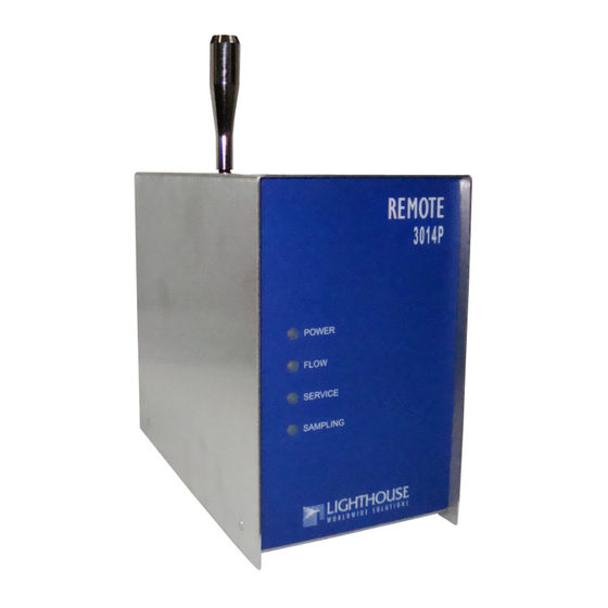
Unpacking, Inspecting and Installing Operation Understanding the LEDs The front-panel LEDs have special meanings when illuminated. The figure below shows location of the LEDs and gives a brief description of their meaning. Figure 3-1 Front Panel LEDs • The green POWER LED turns on when the instrument is powered •... -
Page 24: Connections
Lighthouse REMOTE 2014P, 3014P, 5014P Operating Manual 4. MODBUS protocol (see “MODBUS Register Map v1.48” on page A-1). 5. Ethernet and RS-485 communications 6. 3000 record storage in a rotating buffer 7. Internal pump with auto-adjusting flow control Connections The top of the instrument has one connection, the sampling inlet. -
Page 25: Communication Ports
Unpacking, Inspecting and Installing 1. DIP Switches (under plate): for changing the addressing of the instrument and for selecting to use the Remote Display option. 2. Power Switch: for turning the instrument ON and OFF. 3. Power Connector: +24V power supply. 4. -
Page 26: 4-20Ma Analog Inputs
PC. Failure to heed this This REMOTE instrument has two 4-20mA analog inputs that can be warning can result in fitted with up to four 4-20mA environmental sensor. Lighthouse damage to PC, instrument provides optional environmental sensors: Temperature/Relative or both. -
Page 27: Dip Switches
This REMOTE instrument uses an external power supply rated at If the REMOTE will be used +24VDC at 0.62A. The connector incorporates a threaded ring to lock with the Lighthouse it into position, preventing accidental disconnects. MiniManifold, do NOT use the REMOTE 24VDC... -
Page 28: Remote Display Connector
Lighthouse REMOTE 2014P, 3014P, 5014P Operating Manual Remote Display Connector An optional REMOTE Display touchscreen can be connected to the 2014P, 3014P or 5014P instrument. This display is a color touchscreen interface. A longer cable can be attached to the Display so that the instrument can be running in a clean area while the Display is mounted on a wall bracket in a different area. -
Page 29: Using The Usb Port To Connect To A Pc
Unpacking, Inspecting and Installing Using the USB Port to connect to a PC Note: To connect the instrument to a computer using the USB port, make sure Make sure the USB driver has been that the driver has been installed first. Connecting the instrument to the installed on the PC before PC and applying power before the driver has been installed will be connecting and applying... -
Page 30: Ethernet Configuration
Lighthouse REMOTE 2014P, 3014P, 5014P Operating Manual 6. Identify the computer port that has been added to the PC by using the “Properties” of My Computer and examining the COM ports. USB ports are generally added to the bottom of the list and named USB COM port ’x’. -
Page 31: Definitions Of Terms Used
Unpacking, Inspecting and Installing The Lighthouse Worldwide Solutions REMOTE P instruments incorporate MODBUS TCP/IP communication over Ethernet. Connecting a REMOTE P particle counter directly to an Ethernet network should only be done with the permission and guidance of the network administrator. -
Page 32: Preparing For Network Installation
Lighthouse REMOTE 2014P, 3014P, 5014P Operating Manual • Subnet - a logical grouping of hosts based on their IP addresses. • TCP/IP - a communication protocol suite that is used for the Internet and a large number of LANs that allows hosts to share data. -
Page 33: Configure Device
When this is needed, make sure the instrument is reprogrammed to its previous network settings before reattaching to the LAN. Contact Lighthouse Technical Support or the network administrator for additional information. Straight-through Cat5 Setup:... -
Page 34: Program The Interface
Lighthouse REMOTE 2014P, 3014P, 5014P Operating Manual Apply power to the REMOTE. Apply power to the PC if it is not already running. Observe the LEDs on the hub/switch RJ45 connector - blinking indicates network activity. Observe the network LEDs on the instrument’s RJ45 receptacle - they should blink indicating activity. - Page 35 Unpacking, Inspecting and Installing A command prompt window will open. Clear the ARP Cache by typing arp -d * at the command line and press Enter. Ignore any error messages that indicate the address table doesn’t exist or has no entries. Figure 3-9 Clear Address Table Command The next step requires the unit’s assigned IP and its MAC address.
- Page 36 Lighthouse REMOTE 2014P, 3014P, 5014P Operating Manual 10. Type telnet xx.xx.xx.xx 9999 and press Enter. This command accesses the telnet port of the instrument. The expected error message from Step 9. is shown in the example screen below. Figure 3-12 Telnet 9999 You will have 4 seconds to respond in the next step.
- Page 37 Unpacking, Inspecting and Installing Figure 3-14 Assigning IP Address 13. Type to set the Gateway IP address. Type the Gateway IP address and press Enter. Figure 3-15 Assigning Gateway IP Address 14. Type to set the Netmask. type the desired Netmask value and press Enter.
- Page 38 Changing the telnet password or providing one is discouraged, except for absolute security requirements. If a password is applied and forgotten, the instrument will have to be returned to Lighthouse to get the password cleared. Figure 3-17 Telnet Config Password Screen 16.
-
Page 39: Connect Remote P To Ethernet Lan
The data can be downloaded real-time to LMS Express RT or to a Lighthouse Monitoring System; the instrument can run standalone until you decide to view the data. The data can then be downloaded to LMS Express or LMS XChange manually. - Page 40 Lighthouse REMOTE 2014P, 3014P, 5014P Operating Manual 3-20 248083408-1 Rev 1...
-
Page 41: Chapter 4 Programming
Programming General The REMOTE 2014P, 3014P or 5014P can be programmed using the MODBUS Protocol or by using the optional REMOTE Display. The Information full MODBUS protocol is detailed in Appendix A. This chapter contains the information needed to program the basic configuration for the instrument to meet your needs. -
Page 42: Dip Switch Settings
Lighthouse REMOTE 2014P, 3014P, 5014P Operating Manual DIP Switch GENERAL DEFINITIONS Settings OFF (DOWN) = 0, ON (UP) = 1 Table 4-1 DIP Switch settings Position# Description Setting Binary Bit 0 OFF=0, ON=1 Binary Bit 1 OFF=0, ON=1 Binary Bit 2... -
Page 43: Addressing
Programming Addressing Note: The following table details the addresses set by the binary DIP switches Because Address 0 is reserved for 1-6. broadcasting in RS-485 communications, Address Table 4-2 DIP Switch Addressing 1 is set whenever all of the dip switches are OFF or DIP SWITCHES DIP SWITCHES when DIP switch1 is ON. -
Page 44: Communicating With The Instrument
Lighthouse REMOTE 2014P, 3014P, 5014P Operating Manual Table 4-2 DIP Switch Addressing DIP SWITCHES DIP SWITCHES ADDRESS ADDRESS 1 2 3 4 5 6 1 2 3 4 5 6 1 1 1 0 1 0 1 1 1 0 1 1... -
Page 45: Rs-485 Port
"star" or hub-based configuration on the network. If the or both. topology is unknown or the user is unsure how it should be installed, please contact Lighthouse before installation. WARNING: A standard Cat5/Cat6 cable is used to connect the instrument to an... -
Page 46: Rs-232 Communications
Lighthouse REMOTE 2014P, 3014P, 5014P Operating Manual RS-232 Communications The instrument can use RS232 as a communication mode by using the optional USB to RS232 Converter cable. The cable is connected to the RJ-45 Port on the Remote and to any USB port on a PC. -
Page 47: Setting The Real Time Clock
Programming Setting the Real Time Clock The Real Time Clock (RTC) can be read in registers 40027 and 40028: Table 4-4 Real Time Clock Registers Register Data Type Description 40027 signed integer Real Time Clock (RTC) [high]. Works in conjunction with 40028. Displays date and time, in number of seconds since midnight, 1/1/1970. - Page 48 Lighthouse REMOTE 2014P, 3014P, 5014P Operating Manual The low word register for Sample Time is 40034. The low word register for Hold Time is 40032. The low word register for Initial Delay is 40030. Table 4-6 Instrument Parameters Register Data Type...
-
Page 49: Running The Instrument
Programming Running the The REMOTE can be run in several different ways. The applicable action commands are discussed here: Instrument Table 4-7 Action Commands Value Action Saves all writable 4xxxx register values to the EEPROM. Clears the Data Buffer. Record count is set to zero. Saves the instrument parameters in the 40xxx registers to the EEPROM. -
Page 50: Manual Counting Mode
Lighthouse REMOTE 2014P, 3014P, 5014P Operating Manual MANUAL Counting Mode In Manual counting mode, the sample time is based on when the counter is instructed to stop counting. At that point, a data record is recorded and the sample time is the interval between the command to start counting and the command to stop counting. -
Page 51: Chapter 5 Maintenance Procedures
Calibration To maintain optimum performance of this instrument, it should be recalibrated annually by a Lighthouse Authorized Service Provider. Cleaning This procedure may be superceded by customer requirements; however, not under any circumstances apply Acetone to the REMOTE ’P’... - Page 52 Purge Test again. After the instrument has met the requirement of the Purge test, return the instrument to its normal location and operating status. If the instrument still fails the Purge Test, contact Lighthouse Tech Support for assistance. 248083408-1 Rev 1...
-
Page 53: Appendix A Modbus Register Map V1.48
MODBUS Register Map v1.48 MODBUS Register Map v1.48 COMM Lighthouse particle counters with MODBUS have the following communications settings: Settings Table A-1 MODBUS Communications Settings Baud Rate 19200 Data Bits Stop Bits None Parity RS-232C or RS-485 Standard Hardware Protocol... -
Page 54: Register Map
Lighthouse REMOTE 2014P, 3014P, 5014P Operating Manual Register Map Sensor Settings Registers Instrument settings are stored in holding registers (the 4xxxx series), which are mostly read/writable. Not all holding registers are writable. Table A-3 describes the content of these registers. - Page 55 MODBUS Register Map v1.48 Table A-3 Sensor Settings Registers Register Data Type Description 40020 ASCII string Model Name char[10], char [11] 40021 ASCII string Model Name char[12], char [13] 40022 ASCII string Model Name char[14], char [15] 40023 unsigned integer Flow Rate.
- Page 56 Lighthouse REMOTE 2014P, 3014P, 5014P Operating Manual Table A-3 Sensor Settings Registers Register Data Type Description 40034 unsigned integer Sample Time [low] 40035 unsigned integer Data Set [high]. Works in conjunction with 40036. Data entered here is applied to the device through the command register.
- Page 57 MODBUS Register Map v1.48 Table A-3 Sensor Settings Registers Register Data Type Description 40203 ASCII string Location_1_char[6], char[7] 40996 ASCII string Location_200_char[0], char[1] (NULL terminated string) 40997 ASCII string Location_200_char[2], char[3] 40998 ASCII string Location_200_char[4], char[5] 40999 ASCII string Location_200_char[6], char[7] 400 Locations Available (Register 40050 Bit 3 = 1) 40200 ASCII string...
- Page 58 Lighthouse REMOTE 2014P, 3014P, 5014P Operating Manual Printer Option (40049) displays the configuration of the printer function of the instrument. Table A-4 Printer Options Description Unused - Non-writable Print on sample (1 - Enabled, 0 - Disabled) 2-15 Reserved If Bit 1 of Register 40049 is set, the instrument will print the last recorded data at the end of each sample.
-
Page 59: Device Status
MODBUS Register Map v1.48 Device Status The Device Status register (40003) displays the current status of the device. Table A-6 Device Status Description RUNNING: Set when a start command is executed remotely via Command 9 (manual start) or Command 11 (instrument start) or through the user interface. -
Page 60: Data And Alarm Registers
Lighthouse REMOTE 2014P, 3014P, 5014P Operating Manual Table A-7 Command Register Value Action Manual Start. The instrument samples continuously until it receives a Manual Stop command. Ignores local timing parameters. Sets Sample Time for data record to equal the time interval between the Manual Start and Manual Stop command. If applicable to device, does not start pump. - Page 61 MODBUS Register Map v1.48 The 43xxx register series is used to determine which particle data channel is ENABLED and which are set to ALARM ENABLE. These registers supersede the older Data Enable Registers (31xxx) which have been obsoleted. Table A-8 Enable/Disable Bits Description DATA ENABLE (0=disable;...
-
Page 62: Enable Alarming For A Channel
Lighthouse REMOTE 2014P, 3014P, 5014P Operating Manual Table A-9 Alarm Enable Registers Register Data Type Description 43041 unsigned int Enable for Analog Channel 1 [high] 43042 unsigned int Enable for Analog Channel 1 [low] 43043 unsigned int Enable for Analog Channel 2 [high]... -
Page 63: Threshold Setup Registers
MODBUS Register Map v1.48 Threshold Setup Registers Threshold data is stored in the input registers in the 45xxx series which are read/write. All threshold data items are 4 bytes long and are stored across 2 registers. Byte and word ordering is big-endian. Thus, data items are formed by placing the high bytes in front of the low bytes. -
Page 64: Setting The Alarm Threshold Value
Lighthouse REMOTE 2014P, 3014P, 5014P Operating Manual Setting the Alarm Threshold Value The Alarm Threshold Value is set in the low register of the channels. Table A-12 Alarm Threshold Registers set to default value Particle Threshold Registers Channel Value 45009 - 45010... - Page 65 MODBUS Register Map v1.48 The first record in the data buffer is located at Index=0. The most recently saved value is at Index=-1. Table A-13 Data Registers Register Data Type Description 30001 signed integer Timestamp [high] (# of seconds since midnight, 1/1/1970) 30002 signed integer Timestamp [low]...
-
Page 66: Device Status Word (30007 - 30008
Lighthouse REMOTE 2014P, 3014P, 5014P Operating Manual Table A-13 Data Registers Register Data Type Description 30044 IEEE Float Analog Channel 2 [low] 30045 IEEE Float Analog Channel 3 [high] 30046 IEEE Float Analog Channel 3 [low] 30047 IEEE Float Analog Channel 4 [high]... -
Page 67: Valid Data In Channels (30073 - 30076
MODBUS Register Map v1.48 If multiple states occur, the bits are added together. For example, a Flow Alert and a Particle Overflow would return a value of 6 in register 30008 (bits 1 and 2 are set TRUE). Table A-14 Device Status Word Description Laser Alert Status 0 = Laser is OK... -
Page 68: Data Type Registers
Lighthouse REMOTE 2014P, 3014P, 5014P Operating Manual Data Type Registers Note: The 41xxx register series is used to identify the type of data items in the All data records have the same data types 30xxx series. The Data Type registers run in parallel with the Data assigned to them. -
Page 69: Data Units Registers
MODBUS Register Map v1.48 Note: Particle data items are typed specially. They contain numbers, Only Particle data types have numbers in sometimes a space and sometimes a period used as a decimal point. their strings. These entries are used to identify particle channel sizes and are always expressed in microns. - Page 70 Lighthouse REMOTE 2014P, 3014P, 5014P Operating Manual Table A-17 Data Units Units Description Units Description Meters ft^2 Square feet mBar Milli-bar Square meters Volts ft^3 Cubic feet Milli-volts Cubic meters Amperes Liters Milli-amps Cubic feet per minute Ohms Cubic meters per minute...
-
Page 71: Appendix B Zero Count Test
30 minutes to purge it and repeat the test. If the instrument still fails the Zero Count Test, call Lighthouse Technical Support for assistance. After the instrument meets the requirements of the Zero Count test, turn it off, remove the Purge Filter and return the instrument to its normal location and operating status. - Page 72 Lighthouse REMOTE 2014P, 3014P, 5014P Operating Manual 248083408-1 Rev 1...
-
Page 73: Appendix C Limited Warranty
Upon expiration of the initial two-year warranty, all parts and of two years, except as noted below, without regard to whether repairs completed by an authorized Lighthouse repair technician any claimed defects were discoverable or latent on the date of are subject to a six (6) month warranty. - Page 74 Lighthouse REMOTE 2014P, 3014P, 5014P Operating Manual 248083408-1 Rev 1...
- Page 75 Index Numerics 2014P instrument 2-1 Clear LAT 3-19 3014P instrument 2-1 Clear the Data Buffer 4-9 4-20mA Analog Inputs 3-6 Clearing the Address Table 3-15 5014P instrument 2-1 Clearing the ARP Cache 3-19 5-port hub 3-12 CMD 3-14 Command Console 3-14 Command Register A-7 Communicating with the Instrument 4-4 Communication Mode 4-2...
- Page 76 Lighthouse REMOTE 2014P, 3014P, 5014P Operating Manual Settings 4-2 Dip Switches 3-5 LAN 3-11 LAN topology 3-5, 4-5 Laser Source 2-5 Lighthouse Monitoring System 3-19 Enable Alarming A-10 Limitation Of Warranties C-1 Ethernet Configuration 3-13 Limited Warranty C-1 External Start Counter 4-9...
- Page 77 Index Preventive Maintenance 5-1 Power Supply Input 2-4 Programming Size Range 2-4 DIP Switches 4-2 Storage Temp/RH 2-4 Supporting Software 2-4 Vacuum Source 2-4 Weight 2-4 Zero Count Level 2-4 Real Time Clock REMOTE 5014P Setting 4-7 4 Channel Threshold 2-5 Real-time system 3-19 6 Channel Threshold 2-5 Register Map A-2...
- Page 78 Lighthouse REMOTE 2014P, 3014P, 5014P Operating Manual Laser safety information 1-1 Save 4-9 Saving the Settings 3-18 Warning Sensor Settings Registers A-2 Infrared Radiation 1-1 Set adapter’s IP address 3-16 Warranty C-1 Setting DIP Switches 4-2 Warranty Of Repairs After Initial Two (2) Year...
Need help?
Do you have a question about the Remote Series and is the answer not in the manual?
Questions and answers