
Related Manuals for Beckhoff EP9214-0023

Summary of Contents for Beckhoff EP9214-0023
- Page 1 Documentation EP9214-0023 and EP9224-0023 Power Distribution for EtherCAT Box Modules Version: 2.3.1 Date: 2018-04-10...
-
Page 3: Table Of Contents
Current limitation, switching the load circuits off .............. 46 4.4.3 Setting the current limitation .................... 47 4.4.4 Status LEDs and status bits ..................... 48 EP9214-0023.......................... 50 4.5.1 EP9214-0023 - Object description ................... 50 4.5.2 EP9214-0023 - Process image .................. 65 EP9224-0023.......................... 66 4.6.1 EP9224-0023 - Diagnostic functions................ 66 4.6.2 EP9224-0023 - Object description ................... 79... - Page 4 Table of contents Support and Service ........................ 111 Version: 2.3.1 EP9214-0023 and EP9224-0023...
-
Page 5: Foreword
The TwinCAT Technology is covered, including but not limited to the following patent applications and patents: EP0851348, US6167425 with corresponding applications or registrations in various other countries. ® EtherCAT is registered trademark and patented technology, licensed by Beckhoff Automation GmbH, Germany Copyright © Beckhoff Automation GmbH & Co. KG, Germany. -
Page 6: Safety Instructions
All the components are supplied in particular hardware and software configurations appropriate for the application. Modifications to hardware or software configurations other than those described in the documentation are not permitted, and nullify the liability of Beckhoff Automation GmbH & Co. KG. Personnel qualification This description is only intended for trained specialists in control, automation and drive engineering who are familiar with the applicable national standards. -
Page 7: Documentation Issue Status
FF - firmware version HH - hardware version Example with ser. no.: 55 09 01 00: 55 - week of production 55 09 - year of production 2009 01 - firmware version 01 00 - hardware version 00 EP9214-0023 and EP9224-0023 Version: 2.3.1... -
Page 8: Product Overview
• digital outputs with 0.5 or 2 A output current • analog inputs and outputs with 16 bit resolution • Thermocouple and RTD inputs • Stepper motor modules XFC (eXtreme Fast Control Technology) modules, including inputs with time stamp, are also available. Version: 2.3.1 EP9214-0023 and EP9224-0023... -
Page 9: Fig. 2 Ethercat Box With M8 Connections For Sensors/Actuators
EtherCAT, which is available for download from our website (www.beckhoff.com) Note under Downloads. XML files You will find XML files (XML Device Description Files) for Beckhoff EtherCAT modules on our website (www.beckhoff.com) under Downloads, in the Configuration Files area. Note EP9214-0023 and EP9224-0023... -
Page 10: Ep9214 - Introduction
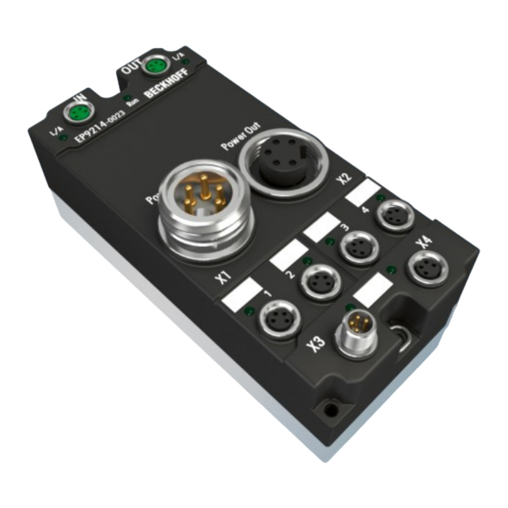
EP9214 - Introduction Fig. 4: EP9214 Power distribution for EtherCAT Box (24 V The EP9214-0023 enables connection of four power supply branches. In each branch the current consumption for the control voltage U and the peripheral voltage U is monitored, limited, and, if necessary, switched off. -
Page 11: Ep9224 - Introduction
In error case it is stopped, so a history of the system parameters from before the error case can be read out. This enables a much quicker error localization. EP9214-0023 and EP9224-0023 Version: 2.3.1... -
Page 12: Technical Data
EN 60068-2-6 / EN 60068-2-27 EMC immunity/emission conforms to EN 61000-6-2 / EN 61000-6-4 Dimensions 126 mm x 60 mm x 40 mm Weight approx. 450 g Installation position variable Protection class IP65, IP66, IP67 (according to EN 60529) Approvals CE, UL in preparation Version: 2.3.1 EP9214-0023 and EP9224-0023... -
Page 13: Mounting And Cabling
Mounting and cabling Mounting and cabling Mounting 3.1.1 Dimensions Fig. 6: Dimensions of the EtherCAT Box Modules All dimensions are given in millimeters. EP9214-0023 and EP9224-0023 Version: 2.3.1... - Page 14 Protect all module connections from soiling during installation!The protection classes IP65, IP66, IP67 (in accordance with EN 60529) are ensured only if all connectors are wired or Note sealed! Unused connectors must be sealed with suitable protective caps (see Beckhoff cat- alogue for connector sets and protective caps)! Cooling plate The EP9214 module has a cooling plate on the underside.
-
Page 15: Nut Torque For Connectors
ZB8800 is also a max. torque of 0.5 Nm permissible. Fig. 7: EtherCAT Box with M8 connectors M12 connectors It is recommended to pull the M12 connectors tight with a nut torque of 0.6 Nm. Fig. 8: EtherCAT Box with M8 and M12 connectors EP9214-0023 and EP9224-0023 Version: 2.3.1... -
Page 16: Ethercat
We recommend fastening the 7/8" plug connectors with a torque of 1.5 Nm. Fig. 9: 7/8" plug connectors Torque socket wrenches Fig. 10: ZB8801 torque socket wrench Ensure the right torque Use the torque socket wrenches available by Beckhoff to pull the connectors tight (ZB8800, ZB8801-0000)! Note EtherCAT 3.2.1... -
Page 17: Fig. 11 Ethercat Box: M8 (30 Mm Housing)
Fig. 11: EtherCAT Box: M8 (30 mm housing) Fig. 12: EtherCAT Box: M8 60 mm housing (EP9214 for example ) Fig. 13: Coupler Box: M12 Assignment There are various different standards for the assignment and colors of connectors and cables for Ethernet/ EtherCAT. EP9214-0023 and EP9224-0023 Version: 2.3.1... -
Page 18: Ethercat - Fieldbus Leds
M8 connectors were changed to the colors of EN61918 (yel- low, orange, white, blue).So different color coding exists. But the electrical properties are absolutely identical. EtherCAT connectors The following connectors can be supplied for use in Beckhoff EtherCAT systems. Designation Plug connector Comment ZS1090-0003... - Page 19 EtherCAT statuses The various statuses in which an EtherCAT module may be found are described in the Ba- sic System Documentation for EtherCAT, which is available for download from our website Note (www.beckhoff.com) under Downloads. EP9214-0023 and EP9224-0023 Version: 2.3.1...
-
Page 20: Power Supply
• Power In: left-hand 7/8" plug for the feed-in of supply voltages • Power Out: right-hand 7/8" socket for the onward feeding of supply voltages Fig. 15: EP9214-0023 - 7/8" connectors The contacts of the 7/8" plug connectors can conduct a maximum current of 16 A (40°C). -
Page 21: Fig. 16 Pin Assignment Of 7/8" Plug Connectors
Observe the maximum current of the 7/8" plug connectors! Also ensure when relaying the supply voltages Us and Up onward that the maximum per- missible current of 16 A / 40 °C for each 7/8" plug connector is not exceeded! Attention EP9214-0023 and EP9224-0023 Version: 2.3.1... -
Page 22: Power Leds
The power supply voltage, Us, is not present Green illuminated The power supply voltage, Us, is present Up (peripheral voltage) The power supply voltage, Up, is not present Green illuminated The power supply voltage, Up, is present Version: 2.3.1 EP9214-0023 and EP9224-0023... -
Page 23: Power Cable Conductor Losses M8
8 m power cable with 0.34 mm² cross-section has a voltage drop of 3.2 V at 4 A. EP92x4 Power Distribution Modules With EP9214 and EP9224 Power Distribution Modules intelligent concepts for voltage sup- ply are available. Further information may be found under www.beckhoff.com/EP9224. Note EP9214-0023 and EP9224-0023... -
Page 24: Power Cable 7/8
Approbations Cable outside diameter 7.80 ± 0.20 mm Bending radius min. 6 x D (external diameter) Parameter Max. speed 5 m/s, max. acceleration 10 m/s² Number of cycles At least 10 million cycles with a max. travel path of 20 meters Version: 2.3.1 EP9214-0023 and EP9224-0023... - Page 25 10.00 m ZK2030-1314-0010 Angled socket, angled 1.00 m plug ZK2030-1314-0030 3.00 m ZK2030-1314-0050 5.00 m ZK2030-1314-0100 10.00 m Further available power cables and the associated data sheets can be found in the Beckhoff catalogue or on our website (http://www.beckhoff.com). EP9214-0023 and EP9224-0023 Version: 2.3.1...
-
Page 26: Conductor Losses 7/8
6 V. Variations in the output voltage from the power supply unit must also be taken into account. Fig. 19: ZK2030-xxxx-yyy - Conductor losses Alternatively, larger cable cross-section can be used, e.g. 2.5 mm Version: 2.3.1 EP9214-0023 and EP9224-0023... -
Page 27: Power Outputs
Do not confuse the power outputs with the EtherCAT connection Never connect the power cables (M8, 24 V ) to the green-marked EtherCAT sockets of the EtherCAT Box Modules. This can cause the destruction of the modules! Attention EP9214-0023 and EP9224-0023 Version: 2.3.1... -
Page 28: Cabling
Attention boxes! Cabling A list of EtherCAT cables, power cables, sensor cables, Ethernet/EtherCAT connectors and field- configurable connectors can be found under the following link: http://download.beckhoff.com/download/ document/catalog/main_catalog/german/Beckhoff_EtherCAT-Box-Zubehoer.pdf The corresponding data sheets can be found under the following link: https://beckhoff.de/default.asp?ethercat-box/ethercat_box_cables.htm?id=690338951657421 EtherCAT cables Fig. 22: ZK1090-3131-0xxx... -
Page 29: Fig. 23 Zk2020-3132-0Xxx
EtherCAT uses four cable wires for signal transmission. Due to automatic cable detection (auto-crossing) symmetric (1:1) or cross-over cables can be used between EtherCAT devices from Beckhoff. Power cable Fig. 23: ZK2020-3132-0xxx Sensor cables Fig. 24: Selection of Beckhoff sensor cables EP9214-0023 and EP9224-0023 Version: 2.3.1... -
Page 30: Status Leds And Status Bits
(Warning Ux). Flashing The output has been switched off. Switching on again is not yet possible (waiting time of 20 seconds) The output has been deactivated and can be returned to a normal state by a reset. Version: 2.3.1 EP9214-0023 and EP9224-0023... -
Page 31: Monitoring And Reset Contacts
Pin 4: Reset all errors are reset by applying 24 V to the Reset contact. The contacts of the M8 plug connectors can conduct a maximum current of 4 A. EP9214-0023 and EP9224-0023 Version: 2.3.1... -
Page 32: Comissioning And Configuration
Note elconfg.htm?id=1983920606140) and installed according to the installation instructions. At the Beckhoff TwinCAT System Manager the configuration tree can be build in two different ways: • by scanning [} 32] for existing hardware (called "online") and • by manual inserting/appending [} 32] of fieldbus devices, couplers and slaves. -
Page 33: Fig. 30 Appending A New I/O Device (I/O Devices -> Right-Click -> Append Device
Fig. 31: Selecting the device EtherCAT • Append a new box. Fig. 32: Appending a new box (Device -> right-click -> Append Box...) • In the dialog that appears select the desired box (e.g. EP2816-0008), and confirm with OK. EP9214-0023 and EP9224-0023 Version: 2.3.1... -
Page 34: Fig. 33 Selecting A Box (E.g. Ep2816-0008)
Comissioning and Configuration Fig. 33: Selecting a Box (e.g. EP2816-0008) Fig. 34: Appended Box in the TwinCAT tree Version: 2.3.1 EP9214-0023 and EP9224-0023... -
Page 35: Configuration Via Twincat
Here you can add a comment (e.g. regarding the system). Disabled Here you can deactivate the EtherCAT device. Create symbols Access to this EtherCAT slave via ADS is only available if this checkbox is activated. EP9214-0023 and EP9224-0023 Version: 2.3.1... -
Page 36: Fig. 37 Ethercat Tab
Indicates the configuration of the process data. The input and output data of the EtherCAT slave are represented as CANopen process data objects (PDO). The user can select a PDO via PDO assignment and modify the content of the individual PDO via this dialog, if the EtherCAT slave supports this function. Version: 2.3.1 EP9214-0023 and EP9224-0023... -
Page 37: Fig. 38 Process Data Tab
(not selected and greyed out), this indicates that the input is excluded from the PDO assignment. In order to be able do select a greyed out PDO, the currently selected PDO has to be deselected first. EP9214-0023 and EP9224-0023 Version: 2.3.1... - Page 38 It is also possible to add new mailbox requests to the list display. The download requests are sent to the slave in the same order as they are shown in the list. Version: 2.3.1 EP9214-0023 and EP9224-0023...
-
Page 39: Fig. 39 Startup Tab
(CoE) protocol. This dialog lists the content of the object directory of the slave (SDO upload) and enables the user to modify the content of an object from this list. Details for the objects of the individual EtherCAT devices can be found in the device-specific object descriptions. EP9214-0023 and EP9224-0023 Version: 2.3.1... -
Page 40: Fig. 40 Coe - Online Tab
Auto Update If this check box is selected, the content of the objects is updated automatically. Advanced The Advanced button opens the Advanced Settings dialog. Here you can specify which objects are displayed in the list. Version: 2.3.1 EP9214-0023 and EP9224-0023... -
Page 41: Fig. 41 Advanced Settings
If this option button is selected, the list of the objects included in the object - via EDS file directory is read from an EDS file provided by the user. Online tab Fig. 42: Online tab EP9214-0023 and EP9224-0023 Version: 2.3.1... - Page 42 A carrier signal is available at the port, but the port is closed. File Access over EtherCAT Download With this button a file can be written to the EtherCAT device. Upload With this button a file can be read from the EtherCAT device. Version: 2.3.1 EP9214-0023 and EP9224-0023...
-
Page 43: Operation With Or Without Ethercat Master
Via the tab “CoE – Online” you can adjust different settings of the box module. For example, it is possible to adjust the “Nominal Current U ” (Index: 8000:12), by double-clicking to the respective parameter opens the “Set Value Dialog” (see following figure). EP9214-0023 and EP9224-0023 Version: 2.3.1... -
Page 44: Switch Of Behavior
Due to the intelligent current limitation an output current exceeding 7 A is not possible under operating conditions. The additionally installed 7 A micro fuse thus blows only if the upstream electronic switch-off is already defective. The nominal current can be set for each channel individually between 1 A and 4 A. Version: 2.3.1 EP9214-0023 and EP9224-0023... - Page 45 RESET can take place maximally every 20 seconds. Faster successive edges are ignored. Switch-on delay of load circuits 1 to 4 without fieldbus control Here is a table of the startup times, adjustable in the CoE object 0xF80E:11 Description Switch-on delay Fast 10 ms Moderate 100 ms Slow 200 ms EP9214-0023 and EP9224-0023 Version: 2.3.1...
-
Page 46: Current Limitation, Switching The Load Circuits Off
Since undervoltage impairs the function of the safety mechanisms, a warning is given in the process data from an input voltage of 21.5 V. If the voltage falls below 18 V all outputs are switched off and the Error bit is set. Version: 2.3.1 EP9214-0023 and EP9224-0023... -
Page 47: Setting The Current Limitation
Switching load circuits on again after switch-off This takes place either via the process data by EtherCAT or by the reset input directly on the box. Also see about this 2 EP9214-0023 - Process image [} 65] 2 Monitoring and reset contacts [} 31] 4.4.3 Setting the current limitation The switch-off behavior of the individual load circuits can be adapted to the application. -
Page 48: Status Leds And Status Bits
This takes place either via the process data [} 65] by EtherCAT or by the reset input [} 31] directly on the box. 4.4.4 Status LEDs and status bits Below is a table showing the meaning of the status LEDs and status bits for the power outputs (EP9214 for example): Version: 2.3.1 EP9214-0023 and EP9224-0023... - Page 49 Flashing red The output has been switched off. Switching on again is not yet possible (waiting time of 20 seconds) The output has been deactivated and can be returned to a normal state by a reset. EP9214-0023 and EP9224-0023 Version: 2.3.1...
-
Page 50: Ep9214-0023 - Object Description
The description correspond to the display of the CoE objects from the EtherCAT XML De- vice Description. It is strongly recommended to download the latest revision of the corre- Note sponding XML file from the Beckhoff website (http://www.beckhoff.com/english/default.htm? download/elconfg.htm) and follow the installation instructions. The CoE overview contains objects for different intended applications: •... - Page 51 : All outputs are set to their default values (80X0:02, boolean 0x00 (0 Via Fieldbus 80X0:03) : All outputs are set according to their PDOs (70X0:01, 70X0:02) F707:04 Global Reset All error bits are reset boolean 0x00 (0 EP9214-0023 and EP9224-0023 Version: 2.3.1...
- Page 52 Serial number of the EtherCAT slave; the low byte (bit 0-7) UINT32 0x00000000 (0 of the low word contains the year of production, the high byte (bit 8-15) of the low word contains the week of produc- tion, the high word (bit 16-31) is 0 Version: 2.3.1 EP9214-0023 and EP9224-0023...
- Page 53 0x05 (Reset Us)) 1602:05 SubIndex 005 5. PDO Mapping entry (object 0x7020 (DPO Outputs Ch.3), UINT32 0x7020:06, 1 entry 0x06 (Reset Up)) 1602:06 SubIndex 006 6. PDO Mapping entry (10 bits align) UINT32 0x0000:00, 10 EP9214-0023 and EP9224-0023 Version: 2.3.1...
- Page 54 10. PDO Mapping entry (object 0x6000 (DPO Inputs Ch.1), UINT32 0x6000:0F, 1 entry 0x0F (TxPDO State)) 1A00:0B SubIndex 011 11. PDO Mapping entry (object 0x6000 (DPO Inputs Ch.1), UINT32 0x6000:10, 1 entry 0x10 (TxPDO Toggle)) Version: 2.3.1 EP9214-0023 and EP9224-0023...
- Page 55 10. PDO Mapping entry (object 0x6020 (DPO Inputs Ch.3), UINT32 0x6020:0F, 1 entry 0x0F (TxPDO State)) 1A02:0B SubIndex 011 11. PDO Mapping entry (object 0x6020 (DPO Inputs Ch.3), UINT32 0x6020:10, 1 entry 0x10 (TxPDO Toggle)) EP9214-0023 and EP9224-0023 Version: 2.3.1...
- Page 56 11. PDO Mapping entry (object 0xF607 (DPO Inputs De- UINT32 0xF607:0F, 1 vice), entry 0x0F (TxPDO State)) 1A04:0C SubIndex 012 12. PDO Mapping entry (object 0xF607 (DPO Inputs De- UINT32 0xF607:10, 1 vice), entry 0x10 (TxPDO Toggle)) Version: 2.3.1 EP9214-0023 and EP9224-0023...
- Page 57 Subindex 004 4. Allocated TxPDO (contains the index of the associated UINT16 0x1A03 (6659 TxPDO mapping object) 1C13:05 Subindex 005 5. Allocated TxPDO (contains the index of the associated UINT16 0x1A04 (6660 TxPDO mapping object) EP9214-0023 and EP9224-0023 Version: 2.3.1...
- Page 58 0x0000 (0 counter SYNC1 event was too short (DC mode only) 1C32:20 Sync error The synchronization was not correct in the last cycle, (out- boolean 0x00 (0 puts were output too late; DC mode only) Version: 2.3.1 EP9214-0023 and EP9224-0023...
- Page 59 Shift too short as 1C32:13 UINT16 0x0000 (0 counter 1C33:20 Sync error as 1C32:32 boolean 0x00 (0 4.5.1.3 Profile-specific objects (0x6000-0xFFFF) The profile-specific objects have the same meaning for all EtherCAT slaves that support profile 5001. EP9214-0023 and EP9224-0023 Version: 2.3.1...
- Page 60 0x00 (0 1: The output supplies 24 V 6010:07 Channel Error 6010:01 or 6010:02 are set boolean 0x00 (0 6010:0E Sync error boolean 0x00 (0 6010:0F TxPDO State boolean 0x00 (0 6010:10 TxPDO Toggle boolean 0x00 (0 Version: 2.3.1 EP9214-0023 and EP9224-0023...
- Page 61 0x00 (0 1: Us will be switched on 7000:05 Reset Us An error on Us will be reset boolean 0x00 (0 7000:06 Reset Up An error on Up will be reset boolean 0x00 (0 EP9214-0023 and EP9224-0023 Version: 2.3.1...
- Page 62 Index Name Meaning Data type Flags Default 801F:0 DPO Vendor UINT8 0x14 (20 data Ch.2 801F:11 GainS UINT16 0x4000 (16384 801F:12 OffsetS INT16 0x0000 (0 801F:13 GainP UINT16 0x4000 (16384 801F:14 OffsetP INT16 0x0000 (0 Version: 2.3.1 EP9214-0023 and EP9224-0023...
- Page 63 Meaning Data type Flags Default F010:0 Module list UINT8 0x04 (4 F010:01 SubIndex 001 UINT32 0x0000010E (270 F010:02 SubIndex 002 UINT32 0x0000010E (270 F010:03 SubIndex 003 UINT32 0x0000010E (270 F010:04 SubIndex 004 UINT32 0x0000010E (270 EP9214-0023 and EP9224-0023 Version: 2.3.1...
- Page 64 Offset US reserved INT16 0x0000 (0 F81F:17 Gain UP reserved UINT16 0x4000 (16384 F81F:18 Offset UP reserved INT16 0x0000 (0 F81F:19 Gain Tempera- reserved UINT16 0x4000 (16384 ture F81F:1A Offset Tempera- reserved INT16 0x0000 (0 ture Version: 2.3.1 EP9214-0023 and EP9224-0023...
-
Page 65: Ep9214-0023 - Process Image
Comissioning and Configuration 4.5.2 EP9214-0023 - Process image The EP9214 has 4 x 16-bit status data of the four output channels DPO Inputs Channel n. Subsequently, a status word follows for the complete device DPO Inputs Device. In the output section there are 4 x 16-bit output data of the four output channels DPO Outputs Channel n. -
Page 66: Ep9224-0023 - Diagnostic Functions
4.6.1.1 Special features of the EP9224 The EP9224 EtherCAT Box offers all the basic properties of the EP9214-0023. Beyond that it permits more detailed settings and a further-reaching diagnosis of the output channels. The diagnostic information is either directly visible in the process data or can be read out via the logdata.csv log file in the event of an error. - Page 67 LED. An output switch-off due to overcurrent is indicated by a red LED. If one of the outputs was switched off due to a diagnosis, it must be reactivated by an active RESET. EP9214-0023 and EP9224-0023 Version: 2.3.1...
- Page 68 The selection of additional PDOs in the PDO Mapping is required for the use of the diagnostic functions. This allows the display of further diagnostic data [} 69] in the process data section. Additional input PDOs Fig. 52: EP9224 - Additional input PDOs Version: 2.3.1 EP9214-0023 and EP9224-0023...
- Page 69 The DPO Extended Diag Inputs Channel n can be activated with each channel. It continuously indicates the respective current value Peak Value n and the precise time of the arrival Timestamp n. The selection of the triggering event takes place in the CoE object 80x0:15 or 16. EP9214-0023 and EP9224-0023 Version: 2.3.1...
- Page 70 DPO Extended Diag Outputs Channel n The Peak Value and Timestamp data of the respective channel are reset by setting the Reset Extended Diag Data bit. The bit is state-triggered. Fig. 56: EP9224 - DPO Extended Diag Outputs Channel 1 Version: 2.3.1 EP9214-0023 and EP9224-0023...
- Page 71 Thus, for example, in the above case with the setting Maximum Current Us, the value pv_3 is displayed in the process data with the timestamp t3. Selection of the trigger criterion Settings for each output channel The object 80n0:15 or 16 must be adapted for the selection. EP9214-0023 and EP9224-0023 Version: 2.3.1...
- Page 72 Imminent switch-off of Us and Up due to a total current error (edge triggered 0->1) Minimum Current Us Minimum current on Us Maximum Current Us Maximum current on Us Minimum Current Up Minimum current on Up Maximum Current Up Maximum current on Up Version: 2.3.1 EP9214-0023 and EP9224-0023...
- Page 73 In the event of an error, data are still written for a few cycles. The switching-off of a channel is indicated by OFF. The writing rate or scanning rate is 10 ms in the factory setting. The value can be adjusted from 1 ms to 1000 ms in the CoE. EP9214-0023 and EP9224-0023 Version: 2.3.1...
- Page 74 The log file is written when stopping the logger or in the case of an error. The state of the logger can be tracked in the PDO input area. To do this it is necessary to activate the PDO 0x1A10 (see PDO settings [} 68]). Version: 2.3.1 EP9214-0023 and EP9224-0023...
- Page 75 Fig. 65: EP9224 - DPO LOG Status Upload the file from the EP9224 The EP9224 creates the file, giving it the name logdata.csv. This cannot be changed. When uploading, for example, it must be specified accordingly in TwinCAT. EP9214-0023 and EP9224-0023 Version: 2.3.1...
- Page 76 Comissioning and Configuration Fig. 66: EP9224 - Uploading the file Structure of the logging file: logdata.csv The data are saved in the CSV format, so that simple viewing with EXCEL or a corresponding interpretation is possible. Version: 2.3.1 EP9214-0023 and EP9224-0023...
- Page 77 Sum current of Us and Up in A I²t(U...) virtual overload, incremented or decremented depending on the nominal current • from 10% warning • at 100% shut-off Example: slow exceeding of the current (simulation with potentiometer) logdata.csv (zip) EP9214-0023 and EP9224-0023 Version: 2.3.1...
- Page 78 • Continuous increase of the current on channel 1 Us within the recorded range of 3.0 A to 4.9 A, then shut-off takes place. • Overcurrent begins from 180 ms • 100% overload reached (99), channel is switched off • the module now waits for an error correction or an active reset of the error Version: 2.3.1 EP9214-0023 and EP9224-0023...
-
Page 79: Ep9224-0023 - Object Description
The description correspond to the display of the CoE objects from the EtherCAT XML De- vice Description. It is strongly recommended to download the latest revision of the corre- Note sponding XML file from the Beckhoff website (http://www.beckhoff.com/english/default.htm? download/elconfg.htm) and follow the installation instructions. The CoE overview contains objects for different intended applications: •... - Page 80 8010:14 Nominal Nominal total current UINT16 0x0FA0 (4000 Sum Cur- rent 8010:15 Timestamp Trigger condition for extended diagnosis UINT16 0x0000 (0 1 Trigger 8010:16 Timestamp Trigger condition for extended diagnosis UINT16 0x0000 (0 2 Trigger Version: 2.3.1 EP9214-0023 and EP9224-0023...
- Page 81 8030:14 Nominal Nominal total current UINT16 0x0FA0 (4000 Sum Cur- rent 8030:15 Timestamp Trigger condition for extended diagnosis UINT16 0x0000 (0 1 Trigger 8030:16 Timestamp Trigger condition for extended diagnosis UINT16 0x0000 (0 2 Trigger EP9214-0023 and EP9224-0023 Version: 2.3.1...
- Page 82 4.6.2.1.6 Index 8040 LOG Settings Index Name Meaning Data type Flags Default 8040:0 LOG Set- UINT8 0x11 (17 tings 8040:11 Sampling permitted values: UINT16 0x000A (10 Rate 1: 1 ms 10: 10 ms 25: 25 ms 100: 100 ms Version: 2.3.1 EP9214-0023 and EP9224-0023...
- Page 83 Temperature Internal temperature of power INT16 0x0000 (0 stage F607:16 Peak Value 1 Extended diagnosis INT16 0x0000 (0 F607:17 Peak Value 2 Extended diagnosis INT16 0x0000 (0 F607:18 Timestamp 1 UINT64 F607:19 Timestamp 2 UINT64 EP9214-0023 and EP9224-0023 Version: 2.3.1...
- Page 84 : All outputs are set according to their PDOs (70X0:01, 70X0:02) F707:04 Global Re- All error bits are reset boolean 0x00 (0 F707:11 Reset Ex- Peak Values and time stamps from F607 are reset boolean 0x00 (0 tended Diag Data Version: 2.3.1 EP9214-0023 and EP9224-0023...
- Page 85 16: Minmum Current Us 17: Maximum Current Us 18: Minimum Current Up 19: Maximum Current Up 20: Minimum Voltage Us 21: Maximum Voltage Us 22: Minimum Voltage Up 23: Maximum Voltage Up 25: Maximum Temperature 24: Minimum Temperature EP9214-0023 and EP9224-0023 Version: 2.3.1...
- Page 86 Data type Flags Default 10F0:0 Backup pa- Information for standardized loading and saving of UINT8 0x01 (1 rameter han- backup entries dling 10F0:01 Checksum Checksum across all backup entries of the EtherCAT UINT32 0x00000000 (0 slave Version: 2.3.1 EP9214-0023 and EP9224-0023...
- Page 87 SubIndex 001 1. PDO Mapping entry (object 0x7030 (DPO Outputs UINT32 0x7010:11, 1 Ch.4), entry 0x01 (Output Us)) 1603:02 SubIndex 002 2. PDO Mapping entry (object 0x7030 (DPO Outputs UINT32 0x0000:00, 15 Ch.4), entry 0x02 (Output Up)) EP9214-0023 and EP9224-0023 Version: 2.3.1...
- Page 88 Ch.4 1607:01 SubIndex 001 1. PDO Mapping entry (object 0x7030 (DPO Outputs UINT32 0x7030:11, 1 Ch.4), entry 0x11 (Reset Extended Diag Data)) 1607:02 SubIndex 002 2. PDO Mapping entry (15 bits align) UINT32 0x0000:00, 15 Version: 2.3.1 EP9214-0023 and EP9224-0023...
- Page 89 0x7040:01, 1 entry 0x01 (Start Logger)) 1610:02 SubIndex 2. PDO Mapping entry (object 0x7040 (LOG Control), UINT32 0x7040:02, 1 entry 0x02 (Stop Logger)) 1610:03 SubIndex 3. PDO Mapping entry (14 bits align) UINT32 0x0000:00, 14 EP9214-0023 and EP9224-0023 Version: 2.3.1...
- Page 90 3. PDO Mapping entry (object 0x6000 (DPO Inputs UINT32 0x6000:17, 64 Ch.1), entry 0x15 (Minimum Current Us)) 1A01:04 SubIndex 4. PDO Mapping entry (object 0x6000 (DPO Inputs UINT32 0x6000:18, 64 Ch.1), entry 0x16 (Minimum Current Up)) Version: 2.3.1 EP9214-0023 and EP9224-0023...
- Page 91 3. PDO Mapping entry (object 0x6010 (DPO Inputs UINT32 0x6010:17, 64 Ch.2), entry 0x15 (Minimum Current Us)) 1A03:04 SubIndex 4. PDO Mapping entry (object 0x6010 (DPO Inputs UINT32 0x6010:18, 64 Ch.2), entry 0x16 (Minimum Current Up)) EP9214-0023 and EP9224-0023 Version: 2.3.1...
- Page 92 3. PDO Mapping entry (object 0x6020 (DPO Inputs UINT32 0x6020:17, 64 Ch.3), entry 0x15 (Minimum Current Us)) 1A05:04 SubIndex 4. PDO Mapping entry (object 0x6020 (DPO Inputs UINT32 0x6020:18, 64 Ch.3), entry 0x16 (Minimum Current Up)) Version: 2.3.1 EP9214-0023 and EP9224-0023...
- Page 93 3. PDO Mapping entry (object 0x6030 (DPO Inputs UINT32 0x6030:17, 64 Ch.4), entry 0x15 (Minimum Current Us)) 1A07:04 SubIndex 4. PDO Mapping entry (object 0x6030 (DPO Inputs UINT32 0x6030:18, 64 Ch.4), entry 0x16 (Minimum Current Up)) EP9214-0023 and EP9224-0023 Version: 2.3.1...
- Page 94 SubIndex 3. PDO Mapping entry (object 0xF607 (DPO Inputs UINT32 0xF607:18, 64 Device), entry 0x18 (Timestamp 1)) 1A09:04 SubIndex 4. PDO Mapping entry (object 0xF607 (DPO Inputs UINT32 0xF607:19, 64 Device), entry 0x19 (Timestamp 2)) Version: 2.3.1 EP9214-0023 and EP9224-0023...
- Page 95 Subindex 10. allocated RxPDO (contains the index of the asso- UINT16 0x0000 (0 ciated RxPDO mapping object) 1C12:0B Subindex 11. allocated RxPDO (contains the index of the asso- UINT16 0x0000 (0 ciated RxPDO mapping object) EP9214-0023 and EP9224-0023 Version: 2.3.1...
- Page 96 Subindex 10. allocated TxPDO (contains the index of the asso- UINT16 0x0000 (0 ciated TxPDO mapping object) 1C13:0B Subindex 11. allocated TxPDO (contains the index of the asso- UINT16 0x0000 (0 ciated TxPDO mapping object) Version: 2.3.1 EP9214-0023 and EP9224-0023...
- Page 97 SYNC0 and SYNC1 event was too short (DC mode counter only) 1C32:20 Sync error The synchronization was not correct in the last cycle, boolean 0x00 (0 (outputs were output too late; DC mode only) EP9214-0023 and EP9224-0023 Version: 2.3.1...
- Page 98 Shift too as 1C32:13 UINT16 0x0000 (0 short counter 1C33:20 Sync error as 1C32:32 boolean 0x00 (0 4.6.2.3 Profile-specific objects (0x6000-0xFFFF) The profile-specific objects have the same meaning for all EtherCAT slaves that support profile 5001. Version: 2.3.1 EP9214-0023 and EP9224-0023...
- Page 99 1. 6000:17 Timestamp 1 Time stamp when the peak UINT64 value 6000:13 was measured 6000:18 Timestamp 2 Time stamp when the peak UINT64 value 6000:14 was measured EP9214-0023 and EP9224-0023 Version: 2.3.1...
- Page 100 2. 6010:17 Timestamp 1 Time stamp when the peak UINT64 value 6010:13 was measured 6010:18 Timestamp 2 Time stamp when the peak UINT64 value 6010:14 was measured Version: 2.3.1 EP9214-0023 and EP9224-0023...
- Page 101 3. 6020:17 Timestamp 1 Time stamp when the peak UINT64 value 6020:13 was measured 6020:18 Timestamp 2 Time stamp when the peak UINT64 value 6020:14 was measured EP9214-0023 and EP9224-0023 Version: 2.3.1...
- Page 102 0x12 (18 6040:01 Logger Running 0: Logger still running boolean 0x00 (0 6040:11 Elapsed Time Time since the logger was UINT32 0x00000000 (0 stopped 6040:12 Trigger Reason Reason the logger was stopped UINT16 0x0000 (0 Version: 2.3.1 EP9214-0023 and EP9224-0023...
- Page 103 Reset Up An error on Up will be reset boolean 0x00 (0 7030:11 Reset Extended Diag Data The peak values and time boolean 0x00 (0 stamps of the extended diagno- sis for this channel are deleted. EP9214-0023 and EP9224-0023 Version: 2.3.1...
- Page 104 General information for the UINT8 0x02 (2 modular device profile F000:01 Module index distance Index spacing of the objects of UINT16 0x0010 (16 the individual channels F000:02 Maximum number of modules Number of channels UINT16 0x0005 (5 Version: 2.3.1 EP9214-0023 and EP9224-0023...
- Page 105 F81F:16 Offset US reserved INT16 0x0000 (0 F81F:17 Gain UP reserved UINT16 0x4000 (16384 F81F:18 Offset UP reserved INT16 0x0000 (0 F81F:19 Gain Temperature reserved UINT16 0x4000 (16384 F81F:1A Offset Temperature reserved INT16 0x0000 (0 EP9214-0023 and EP9224-0023 Version: 2.3.1...
-
Page 106: Ep9224-0023 - Process Image
Ip of the channel set in CoE object 8000:14 persists, the channel will be switched off Current Us, Current Up: These two 16-bit process words represent the present current value of Us or Up respectively. Version: 2.3.1 EP9214-0023 and EP9224-0023... -
Page 107: Restoring The Delivery State
Restoring the delivery state To restore the delivery state for backup objects in ELxxxx terminals / EPxxxx boxes, the CoE object Restore default parameters, SubIndex 001 can be selected in the TwinCAT System Manager (Config mode). EP9214-0023 and EP9224-0023 Version: 2.3.1... - Page 108 In some older terminals / boxes the backup objects can be switched with an alternative re- store value: Note Decimal value: 1819238756 Hexadecimal value: 0x6C6F6164 An incorrect entry for the restore value has no effect. Version: 2.3.1 EP9214-0023 and EP9224-0023...
-
Page 109: Appendix
Character Resistance Steam at temperatures >100°C: not resistant Sodium base liquor at room temperature: resistant (ph-Value > 12) > 40°C: not resistant Acetic acid not resistant Argon (technical clean) resistant EP9214-0023 and EP9224-0023 Version: 2.3.1... -
Page 110: Ethercat Box- / Ethercat P Box - Accessories
ZB8801-0003 torque cable key, M12 field assembly/wrench size 13, for torque wrench ZB8801-0000 Further accessories Further accessories may be found at the price list for Beckhoff fieldbus components and at the internet under www.beckhoff.com. Note Version: 2.3.1 EP9214-0023 and EP9224-0023... - Page 111 Beckhoff's branch offices and representatives Please contact your Beckhoff branch office or representative for local support and service on Beckhoff products! The addresses of Beckhoff's branch offices and representatives round the world can be found on her internet pages: http://www.beckhoff.com You will also find further documentation for Beckhoff components there.
-
Page 112: Table Of Figures
EtherCAT Box: M8 60 mm housing (EP9214 for example ) ............Fig. 13 Coupler Box: M12 ........................Fig. 14 EtherCAT-LEDs ........................... Fig. 15 EP9214-0023 - 7/8" connectors....................Fig. 16 Pin assignment of 7/8" plug connectors..................Fig. 17 Power cable conductor losses ..................... Fig. 18 Power cable 7/8".......................... - Page 113 Fig. 67 EP9224 - Structure of the file: logdata.csv .................. Fig. 68 EP9224 - logdata.csv........................Fig. 69 Selecting the Restore default parameters PDO................108 Fig. 70 Entering a restore value in the Set Value dialog................108 EP9214-0023 and EP9224-0023 Version: 2.3.1...
Need help?
Do you have a question about the EP9214-0023 and is the answer not in the manual?
Questions and answers