Table of Contents
Advertisement
Quick Links
F C C N O T I C E ( C l a s s A)
This device complies with Part 15 of the FCC Rules. Operation is subject to the following two conditions: (1) this device may not
cause harmful interference, and (2) this device must accept any interference received, including interference that may cause
undesired operation.
F e d e r a l C o m m u n i c a t i o n s C o m m i s s i o n S t a t e m e n t
NOTE- This equipment has been tested and found to comply with the limits for a Class A digital device, pursuant to Part 15 of the FCC Rules.
These limits are designed to provide reasonable protection against harmful interference in a residential installation. This equipment
generates uses and can radiate radio frequency energy and, if not installed and used in accordance with the instructions, may cause harmful
interference to radio communications. However, there is no guarantee that interference will not occur in a particular installation. If this
equipment does cause harmful interference to radio or television reception, which can be determined by tuning the equipment off and on, the
user is encouraged to try to correct the interference by one or more of the following measures:
Reorient or relocate the receiving antenna.
Increase the separation between the equipment and receiver.
Connect the equipment into an outlet on a circuit different from that to which the receiver is connected.
Consult the dealer or an experienced radio/television technician for help.
C l a s s A I T E :
Class A ITE is a category of all other ITE which satisfies the class A ITE limits but not the class B ITE limits. Such equipment should not be
restricted in its sale but the following warning shall be included in the instructions for use:
Warning - This is a class A product. In a domestic environment this product may cause radio interference in which case the user may be
required to take adequate measures.
C E C l a s s A ( E M C )
This product is herewith confirmed to comply with the requirements set out in the Council Directives on the Approximation of
the laws of the Member States relating to Electromagnetic Compatibility Directive 2004/108/EEC.
Warning - This is a Class A product. In a domestic environment this product may cause radio interference in which case the
user may be required to take adequate measures to correct this interference.
ENGLISH
Advertisement
Table of Contents

Related Manuals for AVer AVerVision VP-1


Summary of Contents for AVer AVerVision VP-1
- Page 1 ENGLISH F C C N O T I C E ( C l a s s A) This device complies with Part 15 of the FCC Rules. Operation is subject to the following two conditions: (1) this device may not cause harmful interference, and (2) this device must accept any interference received, including interference that may cause undesired operation.
- Page 2 The information contained in this documentation is subject to change without notice. In no event will AVer be liable for direct, indirect, special, incidental, or consequential damages arising out of the use or inability to use this product or documentation, even if advised of the possibility of such damages.
-
Page 3: Table Of Contents
Connecting a RGB, Mac Display Monitor or LCD/DLP Projector............. E-6 Connecting an IBM Compatible PC or Macintosh Computer ............E-6 Connecting to a Microscope ......................E-7 Setting Up AVerVision VP-1 ....................E-7 Unfolding the Unit ..........................E-7 Operating Height & Angle ........................ E-8 ... -
Page 5: Package Contents
ENGLISH Thank you for purchasing the AVerVision VP-1. This document camera RCA Cable displays documents, User Manual transparencies and 3D objects onto a TV, LCD or DLP projector making presentations a snap. Power Adapter AVerVision VP-1 is an RGB Cable (VGA Cable) -
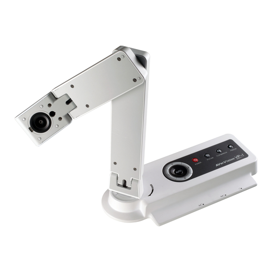
Page 6: Avervision Vp-1 Parts
The illustrations below identify the parts of AVerVision VP-1 Camera head Camera lens Rear panel Control panel Right panel Paper guide TV-RGB switch Resolution switch (10) DC 12V port (11) Composite video output port (12) RGB output port (13) RGB input port... -
Page 7: Technical Specifications
ENGLISH Image Dimension Sensor 1/4" CMOS color image sensor Operating 275mm x 114mm x 335mm Total Pixels 2 Mega Pixels Folded 275mm x 114mm x 70mm Frame Rate 15 fps (max.) Weight 1.2 kg (about 2.64 lb) 1280 x 960 (HI); Analog RGB output 1024 x 768 (MID);... -
Page 8: Making The Connections
The ports on the rear, and right panel of VP-1 enable you to connect the unit to a computer, graphics display monitor or LCD/DLP projector, TV or other device. Illustrated below are the ports and switches that are located at the rear, and right panel of VP-1 with their corresponding labels. -
Page 9: Connecting The Power Adapter
ENGLISH Connect the power adapter to a standard 100V~240V AC power source. Wall outlet Power adapter Locate the VIDEO, or SCART input port of the TV or Video equipment (i.e., VCR) to record your presentation on a videotape and connect it to TV VIDEO OUT port of VP-1. If you are not sure, please refer to the user manual of the TV or Video equipment. Make sure the TV/RGB switch is set to TV. -
Page 10: Connecting A Rgb, Mac Display Monitor Or Lcd/Dlp Projector
Locate the RGB input port of the display device and connect it to RGB OUT port of VP-1. If you are not sure, please refer to the user manual of the device. Make sure the TV/RGB switch is set to RGB. RGB cable LCD/DLP projector LCD / MAC monitor... -
Page 11: Connecting To A Microscope
ENGLISH Connecting the VP-1 to a microscope enables you to examine microscopic Connecting the VP-1 to a microscope enables you to examine microscopic objects on a big screen without straining your eyes. objects on a big screen without straining your eyes. This section provides useful tips on how to setup the VP-1 to meet your needs. -
Page 12: Operating Height & Angle
& & 90° The approximate height of the arm should be 335mm and angled at 53° to display a A4 size landscape document. 335 mm 90° 150 mm The A4 paper marks serve as a guide for placing the A4 document under the camera. The approximate shooting area of VP-1 is 340mm x 255mm. - Page 13 ENGLISH The touch button control panel located on the top side of the VP-1 provides quick access to commonly used functions. AUTO POWER PC/CAM FLIP/MIRROR FREEZE Function Description (1) POWER Turn the unit on/standby. To turn off, press hold POWER button for 5 sec. (2) PC/CAM Switch between Camera and PC mode.
-
Page 14: Control Panel Light Color
The LED on the control panel of VP-1 indicates the status of the unit. Status Power Up Power On Freeze Standby PC Mode Output Red (Flash) Orange Orange (Flash) Red (Flash) Green Green (Flash) This section provides many useful tips on how to solve common problems while using the VP-1. There is no picture on the presentation screen. -
Page 15: Limited Warranty
For a period of time beginning on the date of purchase of the applicable product and extending as set forth in the “Warranty Period of AVer Product Purchased” section below, AVer Information Inc. (“AVer”) warrants that the applicable product (“Product”) substantially conforms to AVer’s documentation for the product and that its manufacture and components are free of defects in material and workmanship under normal use. - Page 16 WARRANTY, OR THE USE OR PERFORMANCE OF ANY PRODUCT, WHETHER BASED ON CONTRACT OR TORT, INCLUDING NEGLIGENCE, OR ANY OTHER LEGAL THEORY, EVEN IF AVER HAS ADVISED OF THE POSSIBILITY OF SUCH DAMAGES. AVER’S TOTAL, AGGREGATE LIABILITY FOR DAMAGES OF ANY NATURE, REGARDLESS OF FORM OF ACTION, SHALL IN NO EVENT EXCEED THE AMOUNT PAID BY YOU TO AVER FOR THE SPECIFIC PRODUCT UPON WHICH LIABILITY IS BASED.
Need help?
Do you have a question about the AVerVision VP-1 and is the answer not in the manual?
Questions and answers