Pfeiffer Vacuum TC 400 Operating Instructions Manual
Electronic drive unit
Hide thumbs
Also See for TC 400:
- Operating instructions manual (36 pages) ,
- Operating instructions manual (10 pages)

Related Manuals for Pfeiffer Vacuum TC 400


Summary of Contents for Pfeiffer Vacuum TC 400
- Page 1 OPERATING INSTRUCTIONS Translation of the Original TC 400 Electronic drive unit...
-
Page 2: Telegram Example
Dear Customer, Thank you for choosing a Pfeiffer Vacuum product. Your new turbopump is designed to support you by its performance, its perfect operation and without interfering your individual application. The name Pfeiffer Vacuum stands for high-quality vacuum technology, a comprehensive and complete range of top-quality products and first-class service. -
Page 3: Table Of Contents
5.2.5 Data types Parameter set General Control commands Status requests Set value settings Additional parameter for the DCU Operation Configuring the connections with the Pfeiffer Vacuum parameter set 7.1.1 Configuring the digital inputs 7.1.2 Configuring digital outputs and relays 3/48... - Page 4 7.5.1 Operating mode display via LED 7.5.2 Temperature monitoring Recycling and disposal General disposal information Dispose of electronic drive unit Malfunctions General Error codes Warning and error messages when operating with DCU Service solutions by Pfeiffer Vacuum Declaration of conformity 4/48...
- Page 5 List of tables List of tables Tbl. 1: Stickers on the product Tbl. 2: Abbreviations used in this document Tbl. 3: Permissible ambient conditions Tbl. 4: Data for use in safety-related applications in accordance with IEC 61508 and IEC 62061 Tbl.
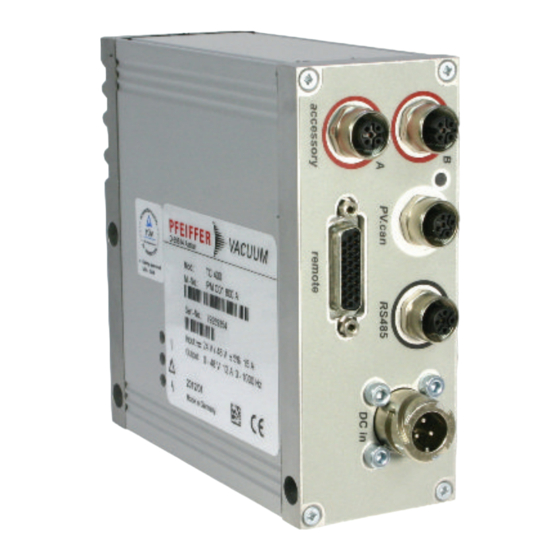
- Page 6 List of figures List of figures Fig. 1: Standard panel TC 400 Fig. 2: Connection diagram for the electronic drive unit. Example: external circuit for "remote" Fig. 3: Rotation speed setting mode pin 7 and pin 11 Fig. 4: Connection options via interface RS-485 Fig.
-
Page 7: About This Manual
Keep the manual for future consultation. 1.1 Validity This operating instructions is a customer document of Pfeiffer Vacuum. The operating instructions de- scribe the functions of the named product and provide the most important information for the safe use of the device. The description is written in accordance with the valid directives. The information in this op- erating instructions refers to the product's current development status. -
Page 8: Stickers On The Product
AI/AO Analog Input/Analog Output Ampere Interrupting Capacity Direct Current Display Control Unit from Pfeiffer Vacuum DI/DO Digital Input/Digital Output Rotation speed value of a vacuum pump (frequency, in rpm or Hz) Handheld Programming Unit, aid for controlling and monitoring parameters... -
Page 9: Safety
Safety 2 Safety 2.1 General safety information The following 4 risk levels and 1 information level are taken into account in this document. DANGER Immediately pending danger Indicates an immediately pending danger that will result in death or serious injury if not observed. ►... -
Page 10: Safety Precautions
Safety DANGER Danger to life from electric shock When establishing the voltages that exceed the specified safety extra-low voltage (according to IEC 60449 and VDE 0100), the insulating measures will be destroyed. There is a danger to life from elec- tric shock at the communication interfaces. -
Page 11: Limits Of Use Of The Product
● Use of accessories or spare parts that are not listed in these instructions 2.7 Functional safety The TC 400 drive unit (electronic drive unit) executes the “Safe Limited Speed” safety function in ac- cordance with EN 61800-5-2. In the event of excess rotation speed, the vacuum pump motor’s commu- tation switches off and brings the drive into a safe state. - Page 12 Safety Characteristics in accordance with EN ISO 13849-1 Characteristic Performance Level Category MTTF Average diagnostic coverage DC Value PL d Cat. 3 high (135 a) Medium (90 % - < 99 %) Tbl. 5: Data for use in safety-related applications in accordance with EN ISO 13849-1 ●...
-
Page 13: Product Description
ID no. 000021320. 3.2 Product features The type TC 400 electronic drive unit is a permanent component of the turbopump. The purpose of the electronic drive unit is to drive, monitor and control the entire turbopump. Feature TC 400 Connection voltage TC 24 V DC ±10 % ... -
Page 14: Connections
RS-485 M12 socket with screw lock for the connection of Pfeiffer Vacuum control panels or PC. The use of a Y-distributor permits the integration into a bus system. Device socket on the rear side of the electronic drive unit for the connection of the turbopump. -
Page 15: Installation
Installation 4 Installation 4.1 Connection diagram DANGER Danger to life from electric shock Power supply packs that are not specified or are not approved will lead to severe injury to death. ► Make sure that the power supply pack meets the requirements for double isolation between mains input voltage and output voltage, in accordance with IEC 61010-1 IEC 60950-1 and IEC 62368-1. -
Page 16: Remote" Connection
The 26-pin D-sub connection with the "remote" designation offers the possibility to operate the electron- ic drive unit via remote control. The accessible individual functions are mapped to "PLC levels". The fol- lowing specifications are the factory settings for the electronic drive unit. They can be configured with the Pfeiffer Vacuum parameter set. 16/48... -
Page 17: Voltage Supply
Installation ► Remove the remote plug from the TC 400 and connect a remote control. ► Utilize the screened plug and cable. Assignment Description, factory setting +24 V DC* output Reference voltage for all digital inputs and outputs (V+) Enable venting (open: off, V+: on) DI motor vacuum Drive motor (open: off;... -
Page 18: Inputs
The digital inputs at the "remote" connection are used to switch various electronic drive unit functions. Inputs DI1 to DI2 are assigned functions in the factory. You can configure them via the RS-485 interface and the Pfeiffer Vacuum parameter set. DI1 (release venting)/pin 2... -
Page 19: Outputs
The contact between pin 21 and pin 22 is open when warnings are pending; relay 3 is active. 4.2.5 RS-485 Pin 24 and pin 25 You can connect a Pfeiffer Vacuum display and control unit (DCU or HPU) or an external PC via pin 24 and pin 25 at the "remote” connection of the electronic drive unit. 19/48... -
Page 20: Interfaces
5 Interfaces 5.1 Interface RS-485 The interface with the designation “RS-485” is intended for the connection of a Pfeiffer Vacuum display and control unit (DCU or HPU) or an external computer. The connections are galvanically safe and are isolated from the maximum supply voltage of the electronic drive unit. The electrical connections are op- tically decoupled internally. -
Page 21: Cross-Linked Via The Rs-485 Connection
3. Connect all devices to the bus with RS-485 D+ and RS-485 D-. 5.2 Pfeiffer Vacuum protocol for RS-485 interface 5.2.1 Telegram frame The telegram frame of the Pfeiffer Vacuum protocol contains only ASCII code characters [32; 127], the exception being the end character of the telegram C. . Basically, a master (e.g. -
Page 22: Telegram Description
Interfaces I1 – I0 Data length dn to d0 dn – d0 Data in the respective data type (see chapter “Data types”, page 23). c2 – c0 Checksum (sum of ASCII values of cells a2 to d0) modulo 256 carriage return (ASCII 13) 5.2.2 Telegram description Data query -->... -
Page 23: Data Types
Interfaces 5.2.5 Data types Data type Description Length Example l1 – l0 boolean_old Logical value (false/true) 000000 corresponds with false 111111 corresponds with true u_integer Positive whole number 000000 to 999999 u_real Positive fixed point number 001571 corresponds with 15.71 u_expo Positive exponential number 1.2E-2 corresponds with 1,2 ·... -
Page 24: Parameter Set
Important settings and function-related characteristics are factory-programmed into the electronic drive unit as parameters. Each parameter has a three-digit number and a description. The use of the parame- ter is possible via Pfeiffer Vacuum displays and control panels, or externally via RS-485 using Pfeiffer Vacuum protocol. - Page 25 Parameter set Display Description Functions Data Unit min. max. type cess fault type Cfg DO2 Output DO2 0 = Rotation speed switch configuration point reached 1 = No error 2 = Error 3 = Warning 4 = Error and/or warning 5 = Set rotation speed reached 6 = Pump on 7 = Pump accelerating...
- Page 26 Parameter set Display Description Functions Data Unit min. max. type cess fault type Cfg Acc A1 Configuration 0 = fan accessory 1 = Venting valve, closed with- connection out current 2 = Heating 3 = Backing pump 4 = Fan (temperature control- led) 5 = Sealing gas 6 = Always "0"...
-
Page 27: Status Requests
Parameter set Display Description Functions Data Unit min. max. type cess fault type CtrlViaInt Control via 1 = remote interface 2 = RS-485 4 = PV.can 8 = Fieldbus 16 = E74 255 = Unlock interface selec- tion IntSelLckd Interface se- 0 = off lection locked 1 = on... -
Page 28: Set Value Settings
Parameter set Display Description Func- Data Access Unit min. max. tions type type fault Nominal Spd Nominal rotational speed 999999 (Hz) DrvPower Drive power 999999 PumpCycles Pump cycles 65535 TempElec Temperature electronics °C 999999 TempPmpBot Temperature pump bottom °C 999999 part AccelDecel Acceleration/deceleration... -
Page 29: Additional Parameter For The Dcu
The basic parameter set is set in the electronic drive unit ex-factory. For controlling con- nected external components (e.g. vacuum measuring instruments), additional parameters (extended parameter set) are available in the corresponding Pfeiffer Vacuum display and control panels. ● Refer to the corresponding operating instructions of the respective components. -
Page 30: Operation
Operation 7 Operation 7.1 Configuring the connections with the Pfeiffer Vacuum parameter set The electronic drive unit is pre-configured with the factory default basic functions and is ready for opera- tion. For individual requirements, you can configure most connections for the electronic drive unit with the parameter set. -
Page 31: Configuring The Analog Input
● The desired accessory output is configured via RS-485 using Pfeiffer Vacuum display and control units or a PC. ● You can find detailed information in the “Electronic drive unit TC 400” operating instruc- tions. 31/48... -
Page 32: Select Interfaces
► Make sure that the gas mode is set correctly by [P:027] in the electronic drive unit. ► Consult Pfeiffer Vacuum before you use gases with higher molecular masses (> 80). Only for vacuum pumps with a temperature management system (TMS) -
Page 33: Set Value Power Consumption
Operation High gas throughput and high rotation speed lead to strong friction heating of the rotor. To avoid over- heating, power to rotation speed characteristics are implemented in the electronic drive unit. The power characteristic enables the operation of the turbopump at any rotation speed with the maximum permissi- ble gas throughput without thermally overloading the turbopump. -
Page 34: Rotation Speed Switch Points
Operation 7.2.4 Rotation speed switch points You can use the rotation speed switch point for the “turbopump operational for the process” message. Exceeding or underrunning the active rotation speed switch point activates or deactivates a signal at the pre-configured output on the electronic drive unit and at the status parameter [P:302]. Rotation speed switch point 1 [P:017] = 0 f (%) -
Page 35: Rotation Speed Setting Mode
3. Check the set rotation speed (parameter [P:308] or [P:397]). 7.2.6 Standby Pfeiffer Vacuum recommends standby mode for the turbopump during process and production stops. When standby mode is active, the electronic drive unit reduces the rotation speed of the turbo pump. -
Page 36: Confirming The Speed Specification
Fluctuations in the power consumption of idling turbopumps and varying fore-vac- uum pressures of the backing pumps require individual settings of the interval operation. Pfeiffer Vacuum recommends interval operation between 5 and 10 hPa. A pressure gauge and a dosing valve are required to set the switching thresholds. -
Page 37: Backing Pump Standby Mode
2. Use this signal for the control of a fore-vacuum safety valve. 7.2.9 Backing pump standby mode In case you are using a Pfeiffer Vacuum backing pump with rotation speed control, this can be used in standby mode by configuring the digital output [P:019] or [P:024]. The power consumption of the turbo- pump has a direct influence on the rotation speed of the backing pump. -
Page 38: 11Venting Modes
Operation Configuring the sealing gas valve ► Using parameter [P:050], switch a connected sealing gas valve on or off via the pre-configured output. Monitoring the sealing gas 1. Set the selected parameter to "13". 2. Set the parameter [P:791] to the desired sealing gas flow for the warning threshold. 3. -
Page 39: Switching Off The Turbopump
7.5.1 Operating mode display via LED LEDs on the electronic drive unit show the basic operating states of the vacuum pump. A differentiated error and warning display is only possible for operation with the Pfeiffer Vacuum display and control unit or a PC. -
Page 40: Recycling And Disposal
8.1 General disposal information Pfeiffer Vacuum products contain materials that you must recycle. ► Dispose of our products according to the following: – Iron –... -
Page 41: Malfunctions
● Only acknowledge for rotational speed f = 0 faulty Err010 Internal device error ● Device defective ● Contact Pfeiffer Vacuum Service. ● Only acknowledge for rotational speed f = 0 Err021 Electronic drive unit ● Incompatible software ver- ● Contact Pfeiffer Vacuum Service. - Page 42 Malfunctions Error Problem Possible causes Remedy code Err043 Internal configuration er- ● Device defective ● Contact Pfeiffer Vacuum Service. Err044 Excess temperature, ● Insufficient cooling ● Improve the cooling electronics ● Check the operating conditions Err045 Excess temperature, ● Insufficient cooling ●...
- Page 43 Problem Possible causes Remedy code Err810 Internal configuration er- ● Incompatible software ver- ● Contact Pfeiffer Vacuum Service. sion ● Only acknowledge for rotational speed f = 0 Err815 Magnetic bearing over- ● Impacts, vibrations ● Contact Pfeiffer Vacuum Service.
-
Page 44: Warning And Error Messages When Operating With Dcu
Malfunctions Error Problem Possible causes Remedy code Wrn115 Pump lower part tem- ● Device defective ● Contact Pfeiffer Vacuum Service. perature evaluation faulty Wrn116 Bearing temperature ● Device defective ● Contact Pfeiffer Vacuum Service. evaluation faulty Wrn117 Pump lower part high ●... -
Page 45: Service Solutions By Pfeiffer Vacuum
We are always focused on perfecting our core competence – servicing of vacuum components. Once you have purchased a product from Pfeiffer Vacuum, our service is far from over. This is often exactly where service begins. Obviously, in proven Pfeiffer Vacuum quality. - Page 46 Service solutions by Pfeiffer Vacuum 5. Prepare the product for transport in accordance with the provisions in the contamination declaration. a) Neutralize the product with nitrogen or dry air. b) Seal all openings with blind flanges, so that they are airtight.
-
Page 47: Declaration Of Conformity
Declaration of conformity Declaration for product(s) of the type: Electronic drive unit TC 400 We hereby declare that the listed product satisfies all relevant provisions of the following European Directives. Electromagnetic compatibility 2014/30/EU Low voltage 2014/35/EC Restriction of the use of certain hazardous substances 2011/65/EU...
Need help?
Do you have a question about the TC 400 and is the answer not in the manual?
Questions and answers