Advertisement
Quick Links
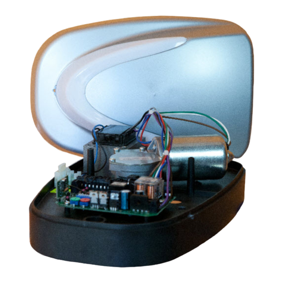
OPERATOR FOR SECTIONAL
AND COUNTERWEIGHT
GARAGE DOORS
UTILE
WARNING!! Before installing, thoroughly read this manual that is an integral
part of the pack
Our products if installed by qualified personnel capable to evaluate risks,
comply with norms UNI EN 12453, EN 12445
The CE mark conforms to European directive
EEC 89/336 + 92/31 + 93/68 D.L. 04/12/1992 N. 476.
Advertisement

Subscribe to Our Youtube Channel
Related Manuals for vds UTILE


Summary of Contents for vds UTILE
- Page 1 OPERATOR FOR SECTIONAL AND COUNTERWEIGHT GARAGE DOORS UTILE WARNING!! Before installing, thoroughly read this manual that is an integral part of the pack Our products if installed by qualified personnel capable to evaluate risks, comply with norms UNI EN 12453, EN 12445 The CE mark conforms to European directive EEC 89/336 + 92/31 + 93/68 D.L.
-
Page 2: Table Of Contents
................PACKING CONTENTS .... VIEW OF TYPICAL AUTOMATION AND NAMES OF COMPONENTS ..................DIMENSIONS .................. TECHNICAL DATA ..........CONSIDERATIONS FOR INSTALLATION ..................5-6-7-8-9 INSTALLATION ................TROUBLESHOOTING ................ SAFETY PRECAUTIONS PACKING CONTENTS 1- Operator with control unit 1- Mounting accessory kit 1- Guide with pre-mounted chain... -
Page 3: View Of Typical Automation And Names Of Components
VIEW OF TYPICAL AUTOMATION AND NAMES OF COMPONENTS Flashing light Door frame Pulling guide Fixing brackets Operator with control unit Manual release G = D Photocells Rubber edge... -
Page 4: Dimensions
DIMENSIONS TECHNICAL DATA 70Kg 100Kg 3000mm Maximum height counterweight door 2700mm Maximum height sectional door Door max width 3000mm 4500mm Supply 230Vac Motor power supply 24Vdc Motor RPM Emergency release Mechanical internal-external -20° C / +55° C Working temperature 4 Kg Weight IP 30 Protection rating... -
Page 5: Installation
INSTALLATION NOTE: For the installation of the operator on counterweight doors you must use the CURVED ARM (optional) Fix the front support of the guide on the door frame or on the wall depending on the measurement taken. Insert and lock the preassembled guide into the front support Bend the brackets according to the Ceiling... - Page 6 Screws Fix the top panel of the door to the pulling bracket with self tapping screws Pulling Bracket Hang the arm to the bracket and fix it with the nut and bolt TE Bolt TE 8x25 Screws Slide Stop 1. Take the engine, release the slide by pushing on the front stop.
- Page 7 Gear Seat Insert the motor bringing the shaft into the seat of the gear Motor Shaft Fix the motor with three self tapping screws Screw Screw Screw...
- Page 8 Make all electrical connections referring to the control unit manual Microswitch Adjust the opening limit Screw switch in the desired position by moving the plastic cam, unscrewing a little the screw Make a knot on the nylon Cart cord and plug it into the hole of the cart release lever passing the site.
- Page 9 Nut M8 To increase or decrease the chain tension adjust nut M8 Ÿ screw the nut to increase tension Ÿ unscrew the nut to decrease tension In case of emergency to unlock the operator pull the release plate Release Plate...
-
Page 10: Troubleshooting
TROUBLESHOOTING SOLUTION PROBLEM PROBABLE CAUSE 230 volt mains voltage Check master switch absent Check for any STOP selectors or commands. Emergency STOP present If not used, check jumper On giving a command with on STOP contact input on the remote the control board control or with the key-switch, the gate... -
Page 11: Safety Precautions
SAFETY PRECAUTIONS These warnings are an essential, integral part of the product and must be given to the user. They provide important indications on the installation, use and maintenance and must be read carefully. This form must be preserved and passed on to subsequent users of the system. The incorrect installation or improper use of the product may be dangerous.
Need help?
Do you have a question about the UTILE and is the answer not in the manual?
Questions and answers