Table of Contents
Advertisement
Quick Links
Advertisement
Table of Contents

Related Manuals for Keysight Technologies N5182BX07

Summary of Contents for Keysight Technologies N5182BX07
- Page 1 Keysight Technologies N5182BX07 Frequency Extender User’s Guide...
- Page 2 DOCUMENT THAT CONFLICT WITH government requirements THESE TERMS, THE WARRANTY beyond those set forth in the © Keysight Technologies, Inc. 2019 TERMS IN THE SEPARATE EULA shall apply, except to the AGREEMENT WILL CONTROL. No part of this manual may be...
-
Page 3: Table Of Contents
N5182BX07 Table of Contents Description ............. . . 6 Verifying the Shipment . - Page 4 Table of Contents Connector Care and Cleaning Precautions ........37 Instrument Markings .
- Page 5 N5182BX07 Frequency Extender 9 kHz to 7.2 GHz Keysight N5182BX07 User's Guide...
-
Page 6: Description
The Keysight N5182BX07 Frequency Extender is an accessory for the MXG (N5182B) or EXG (N5172B) that extends the frequency range of vector signals to cover 9 kHz to 7.2 GHz. The N5182BX07 is especially well suited for 802.11ax measurements, due to its excellent phase noise and EVM. -
Page 7: Verifying The Shipment
If there is physical damage refer to “Contacting Keysight” on page 40. Keep the damaged shipping materials (if any) for inspection by the carrier and an Keysight Technologies representative. Equipment N5182BX07 Frequency Extender, with •... -
Page 8: General Performance
— 100/120V VAC, 220/240 VAC (50/60 Hz) — N5182BX07 maximum power is 160 W Environmental Tests The N5182BX07 complies with all applicable safety and regulatory requirements for the intended location of use. — Operating Environment (for indoor use only) — Operating Temperature 0 to 55 °C —... -
Page 9: Dimensions And Space Requirements
N5182BX07 General Performance Dimensions and Space Requirements Standard installation of the N5182BX07 includes configuration and installation on a customer-provided lab bench or table top of adequate size and strength. Table 1 Dimensions Size, including RF connectors and feet Width 426 mm (16.8") Length 485 mm (19.1") -
Page 10: Specifications
EXG with Option 506 to cover the 802.11ax bands from 2.4 to 7.2 GHz with exceptional error vector magnitude (EVM) accuracy. For frequencies of 5.9 – 7.2 GHz, the N5182BX07 optimizes EVM by holding the MXG or EXG within a narrow frequency and amplitude range, and then adjusting output amplitude with a mechanical attenuator with 1 dB steps. -
Page 11: Definitions And Conditions
Measured (meas) describes an attribute measured during the design phase for purposes of communicating expected performance, such as amplitude drift vs. time. This data is not warranted and is measured at room temperature (approximately 25 °C). Keysight N5182BX07 User's Guide... -
Page 12: Frequency Specifications
Upconverter Band +19 to -144 dBm Step Attenuator in Upconverter Band 0 to 121 dB in 1 dB steps, mechanical RF Input Connector Type N, 50 Ω, nominal RF Output Connector Type N, 50 Ω, nominal Keysight N5182BX07 User's Guide... - Page 13 > 5 GHz to < 5.9 GHz 5.9 GHz to 7.2 GHz +26 dBm (typ) +26 dBm (typ) 1. Power degrades .06 dB / °C from last calibration. Figure 2 Measured Maximum Power with Option 1EA Frequency (GHz) Keysight N5182BX07 User's Guide...
- Page 14 ± 1 dB (nom) 1. Power degrades .06 dB / °C from last calibration. Figure 3 Measured Level Accuracy in Passthrough Band -0.1 -0.2 -0.3 -0.4 -0.5 Frequency (GHz) 5 dBm output power -20 dBm output power Keysight N5182BX07 User's Guide...
- Page 15 ≤ 30 ms (nominal) Table 7 RF Input Limits The N5182BX07 Frequency Extender is designed to be used and controlled by an MXG/EXG instrument with Option FRQ. The MXG/EXG instrument will keep the power levels below the maximum limits. Table 7 is intended for informational purposes only.
-
Page 16: Spectral Purity Specifications
5.9 GHz to 7.2 GHz with power ≤ 10 dBm At 20.48 GHz - 2 * RF Output Frequency < -45 dBc, typical < -45 dBc, typical At 2 * RF Output Frequency - 5.12 GHz Other Frequencies < -65 dBc, typical Keysight N5182BX07 User's Guide... -
Page 17: Modulation
N5182BX07 Specifications Modulation Figure 5 EVM - 802.11ax, 80 MHz Bandwidth (Measured) Output Level (dBm) Output Frequency 5901 MHz 6300 MHz 7125 MHz Keysight N5182BX07 User's Guide... - Page 18 N5182BX07 Specifications Figure 6 EVM - 802.11ax, 160 MHz Bandwidth (Measured) Output Level (dBm) Output Frequency 5950 MHz 6575 MHz 6826.6667 MHz 7200 MHz Keysight N5182BX07 User's Guide...
-
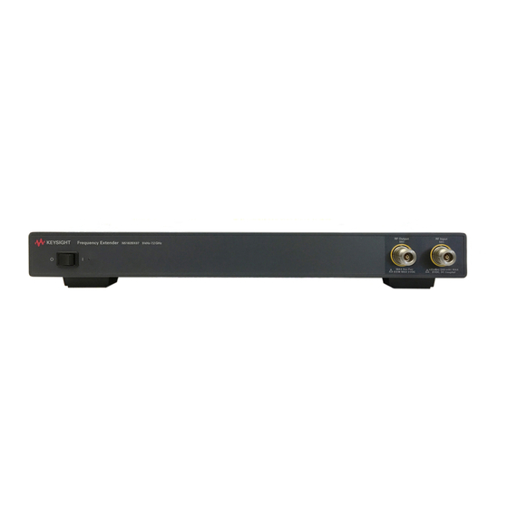
Page 19: Front And Rear Panel Features
LED Status Indicator The light will turn yellow when the instrument is turned on. RF Input (without Option 1EM) Type-N, 50 ohm, nominal. RF Output (without Option 1EM) Type-N, 50 ohm, nominal. Keysight N5182BX07 User's Guide... - Page 20 Type-N, 50 ohm, nominal. 10 MHz In 10 MHz reference input, BNC. USB Port USB, Type C. Line Input Power cord connection. Use the Keysight supplied power cord or one with the same or better electrical rating. Keysight N5182BX07 User's Guide...
-
Page 21: Front And Rear Panel Connections
Front and Rear Panel Connections Front and Rear Panel Connections In the example shown in Figure 9, the N5182BX07 is connected to the MXG from the RF output of the MXG (or EXG) to the RF input of the N5182BX07, using an RF cable with N-Type connectors. -
Page 22: Firmware Initialization
Firmware Initialization To initialize the firmware in the N5182BX07, perform the following steps: 1. Check that there is no USB cable connected between the N5182BX07 and the MXG (or EXG). This cable will be connected in Step 6. 2. Turn on the MXG or EXG. - Page 23 Firmware Initialization 5. Turn on the N5182BX07. 6. Connect the USB cable between the N5182BX07 and the MXG (or EXG). After about 5 seconds, there should be a notification at the bottom of the screen of the MXG (or EXG) showing that it has successfully detected the N5182BX07.
- Page 24 Test Connection of the N5182BX07 If you can't make a connection, check the serial number displayed on your MXG (or EXG) and the serial number of the N5182BX07 to confirm that they match. If they don't match, reselect the USB device.
- Page 25 11. Load a waveform onto the MXG (or EXG) and play the waveform. 12. Confirm Internal Channel Corrections are turned on by pressing IQ > More > Int Channel Correction ON. Signal Studio waveforms should do this automatically, but your own waveform may not. Keysight N5182BX07 User's Guide...
-
Page 26: Extender Power Alignment
3. On MXG front panel, select "Freq" then the "More" hard key. See Figure 17. Figure 17 MXG Front Panel 4. Select the "Freq Extender" softkey and ensure the "Extender State" is set to "On." See Figures 18 and 19. Figure 18 Select Frequency Extender Keysight N5182BX07 User's Guide... - Page 27 Extender Power Alignment Figure 19 Extender State ON 5. Select the "Extender Power Alignment" softkey. See Figure 20. Figure 20 Extender Power Alignment 6. Select the "Configure Power Meter" softkey. See Figure 21. Figure 21 Configure Power Meter Keysight N5182BX07 User's Guide...
- Page 28 • When using a USB Power Sensor, follow the steps in Section b. a. Power Meter Setup (a GPIB to LAN gateway must be used). Set connection Type to VXI-11. See Figures 23 and 24. Figure 23 Connection Type Set to VXI-11 Figure 24 Keysight N5182BX07 User's Guide...
- Page 29 Test the connection and verify it passes. If it fails, re-check the previous steps. b. USB Sensor Setup Plug the USB sensor into the MXG USB port (typically, the top port). See Figure 27. Figure 27 USB Port on MXG Keysight N5182BX07 User's Guide...
- Page 30 8. Once the power meter/sensor is connected and passes the connection test, select the "Return" hard key. 9. Select the "Execute Power Alignment" softkey to run the calibration. Figures 30, 31, and 32. 10. Verify the calibration runs and completes successfully. Keysight N5182BX07 User's Guide...
- Page 31 N5182BX07 Extender Power Alignment Execute Power Alignment Figure 30 Performing Power Alignment Figure 31 Power Alignment Completed Figure 32 Keysight N5182BX07 User's Guide...
-
Page 32: Scpi Commands
N5182BX07 SCPI Commands SCPI Commands To maximize the life of the N5182BX07 attenuator, see the automated test recommendations on page Table 11 SCPI Commands to Turn On the Frequency Extender Turn off the frequency extender in order to change its settings... -
Page 33: Rf Block Diagram
N5182BX07 RF Block Diagram RF Block Diagram RF Block Diagram of N5182BX07 Frequency Extender Figure 33 RF Input RF Output 9 kHz to 6.0 GHz 9 kHz to 7.2 GHz -144 to +26 dBm -112 to +28 dBm Position A... -
Page 34: Safety And Regulatory Information
Declaration of Conformity A copy of the Declaration of Conformity is available upon request, or a copy is available on the Keysight Technologies web site at: https://regulations.about.keysight.com/DoC/search.htm Keysight N5182BX07 User's Guide... -
Page 35: Safety (European Low Voltage Directive)
This ISM device complies with Canadian ICES-001. Cet appareil ISM est conforme a la norme NMB-001 du Canada. Acoustic Statement (European Machinery Directive) • Acoustic noise emission LpA<70 dB Operator position Normal operation mode per ISO 7779 Keysight N5182BX07 User's Guide... -
Page 36: Before Applying Power
10°C from the lowest of the maximum operating temperature of a single instrument. If there are any concerns or special requirements, a Keysight Field Engineer should be consulted to assure instrument(s) temperature compliance and performance." Keysight N5182BX07 User's Guide... -
Page 37: Connector Care And Cleaning Precautions
Connector Care and Cleaning Precautions Remove the power cord to the instrument. To clean the connectors use alcohol in a well ventilated area. Allow all residual alcohol moisture to evaporate, and fumes to dissipate prior to energizing the instrument. Keysight N5182BX07 User's Guide... - Page 38 N5182BX07 Safety and Regulatory Information To prevent electrical shock, disconnect the Keysight N5182BX07 from mains electrical supply before cleaning. Use a dry cloth or one slightly dampened with water to clean the external case parts. Do not attempt to clean internally.
-
Page 39: Instrument Markings
Forty years is the expected useful life of the product. This symbol on all primary and secondary packaging indicates compliance to China standard GB 18455-2001. South Korean Certification (KC) mark; includes the marking's identifier code which follows the format: MSIP-REM-YYY-ZZZZZZZZZZZZZZ. Keysight N5182BX07 User's Guide... -
Page 40: Keysight Support, Services, And Assistance
Keysight representative can determine the warranty status of your unit. Shipping Your Product to Keysight for Service or Repair If you wish to send your instrument to Keysight Technologies for service or repair, please use the original or comparable packaging. - Page 41 Keysight N5182BX07 User's Guide...
- Page 42 This information is subject to change without notice. © Keysight Technologies 2019 Edition 2, November 2019 Supersedes: October 2019 www.keysight.com...
Need help?
Do you have a question about the N5182BX07 and is the answer not in the manual?
Questions and answers