Advertisement
Quick Links
Advertisement

Subscribe to Our Youtube Channel
Related Manuals for ZSK SPRINT Series


Summary of Contents for ZSK SPRINT Series
- Page 1 Quick change system sPRint installation guide Made GerMany ZSK SticKmaSchinen made in Germany...
- Page 3 Quick change system for SPRINT Series Quick change system for SPRINT Series The task of the quick change system is to reduce the machine setup time when changing operation mode between border frame/cap/tubular. After converting the machine to the quick change system, accesories which have not been converted can be connected as customary to the quick change system.
-
Page 4: Scope Of Delivery
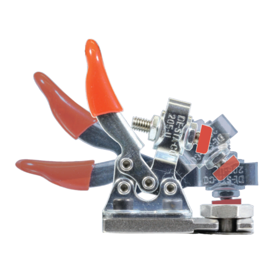
Quick change system for SPRINT Series 1.1 Scope of delivery Add-on kit quick fastener SPRINT Quantity Description Sort term Add-on kit quick fastener 360.998.901 SPRINT Clevis 360.010.207 Horizontal barrel adjuster 205-U 574.103 Cylinder head screw 307.002 M3 x 6 DIN 912 Washer B 3,2 DIN 9021 380.013... - Page 5 Quick change system for SPRINT Series 1.2 Preparations Please read the description of the procedure carefully through. The description contains information which you have to be aware of before the installation. Subassembly of the horizontal barrel adjuster Screw one of the nuts on the clamping screw.
- Page 6 Quick change system for SPRINT Series Screw the second nut on the clamping screw and tighten slightly. Run the installation described above with the second horizontal clamping fixture. Fig. 3: Clamping fixture adaptor (side view) Attach one of the pre-installed...
- Page 7 Quick change system for SPRINT Series Disassembly, conversion and assembly of the carriage Fig. 6: Cover, Disassembly Remove the cover of the pantograph drive for lateral movement. Remove 2 screws with plastic washers on the top and the 3 screws with plastic washers on the back of the cover.
- Page 8 Quick change system for SPRINT Series Disconnect the carriage by removing two fastening screws. On the bottom of the carriage the connection is fixed by 2 locknuts. The drive belt is now loosened from the carriage and can be moved without barriers.
- Page 9 Quick change system for SPRINT Series Fig. 11: Horizontal clamping fixture assembled, carriage (view from above) Mount the two pre-assembled clevises with the horizontal clamping fixture on the carriage. Observe the mounting direction of the horizontal clamping screw. Rotate the mounting screws ca. 1 turn in the thread.
- Page 10 Quick change system for SPRINT Series 1.3 Settings of the quick change system Horizontal clamping fixture, right side Distribute the horizontal clamping fixture on the clevis in the depth direction (arrow) evenly and dexter and align flush with the clevis.
- Page 11 Quick change system for SPRINT Series Cylinder arm frame holder The initial adjustment of the quick change system can only be executed with the cylinder arm frame holder. Remove the two standard mountings of the cylinder arm frame holder. Fig. 16: Cylinder arm frame holder, standard mounting Slide a thrust washer until it stops on the threads of the two centring devices.
- Page 12 Quick change system for SPRINT Series Using a suitable spanner set the absorving energy of the system with which the tubular frame has to be pushed in the guides on the centring devices. Fig. 20: Centring device, force setting Check the setting by moving back and forth the cylinder arm frame holder Change and check the settings of the absorving energy until you find the appropriate setting.
-
Page 13: Contact Pressure
Quick change system for SPRINT Series Set over the lower nuts of the two clamping screws the contact pressure of the two horizontal clamping fixture. The adjustment of the thrust screw is countered with the upper nuts of the two clamping screws. - Page 14 Quick change system for SPRINT Series Checking the panthograph configuration (Tubular frame) After each change to a different mode, you must adjust the settings of the pantograph within the T8 Software again! Load an embroidery pattern in the machine. While loading the pattern you will be asked to adjust the settings of the pantograph.
- Page 15 Quick change system for SPRINT Series Cap attachment The prerequisite for the subsequent description is that the default setting of the quick-change system has been fully implemented. Remove the two standard mountings of the cap attachment. Fig. 26: Cap attachment, standard mounting Slide a thrust washer until it stops on the threads of the two centring devices.
- Page 16 Quick change system for SPRINT Series Using a suitable spanner set the absorving energy of the system with which the cap attachment has to be pushed in the guides on the centring devices. Fig. 30: Centring device, force setting Check the setting by moving back and forth the cap attachment. Change and check the settings of the absorving power until you find the appropriate setting.
- Page 17 Quick change system for SPRINT Series Close both horizontal clamping fixtures. Close the lower clampin device of the cap attachment by tightening the two wing bolts of the clamping device. Fig. 32: Cap attachment, clamping device on the bottom The cap attachment can be used now with the quick change system.
- Page 18 Load an embroidery pattern in the machine. While doing so, you will be asked to adjust the settings of the pantograph. Choose the setting ZSK 99 cap attachment. Confirm your selection with [L8/R8 ] Confirm. Fig. 34: Dialog: Checkpantograph configuration, ZSK 99 cap attachment...
- Page 19 Quick change system for SPRINT Series Border frame The prerequisite of the subsequent description is that the basic setting of the quick change system has been fully implemented. Remove the two standard fastenings of the border frame. Fig. 35: Border frame, standard mounting Slide a thrust washer until it stops on the threads of the two centerings.
- Page 20 Quick change system for SPRINT Series Using a suitable spanner set the absorving energy of the system with which the border frame has to be pushed in the guides on the centring devices. Fig. 39: Centring device, force setting Check the setting by moving back and forth the border frame. Change and check the setting of the absorving energy until you find the appropriate setting.
- Page 21 Quick change system for SPRINT Series Checking the panthograph configuration (Border frame) After each change to another operation mode you have to adjust the settings of the pantograph within the T8 Software Load an embroidery design in the machine. You will be asked to adjust the settings of the pantograph. Select Border frames.
- Page 22 Quick change system for SPRINT Series...
- Page 23 Quick change system for SPRINT Series...
- Page 24 ZSK Stickmaschinen GmbH Subject to change! Änderungen vorbehalten! © ZSK Stickmaschinen GmbH 2015 Printed in Germany [ GB ] 02396T10 Version 1.0 • 08.04.2015/DC...
Need help?
Do you have a question about the SPRINT Series and is the answer not in the manual?
Questions and answers