Advertisement
Quick Links
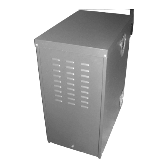
Camray 5 External Boilers
Page 1 of 40
Installation & Maintenance Manual for
Camray 5 External Boilers
Heat is our Element
Making the most of your energy1
Manual Part No. PL61000
Issue No. 2
Date of Issue December 2003
Health & Safety
INFORMATION FOR THE INSTALLER AND SERVICE ENGINEER.
Under the Consumer Protection Act 1987 and the Health and Safety at Work Act 1974, it is a requirement to
provide information on substances hazardous to health (COSHH Regulations 1988).
The Company takes every reasonable care to ensure that these products are designed and constructed to
meet these general safety requirements, when properly used and installed.
To fulfil this requirement products are comprehensively tested and examined before dispatch.
This appliance may contain some of the materials below.
When working on the appliance it is the Users/Engineers responsibility to ensure that any necessary personal
protective clothing or equipment is worn appropriate to parts that could be considered as being hazardous to
health and safety.
file://D:\PL61000\PL61000.htm
14/04/2005
Advertisement

Related Manuals for Boulter Buderus Camray 5


Summary of Contents for Boulter Buderus Camray 5
- Page 1 Camray 5 External Boilers Page 1 of 40 Installation & Maintenance Manual for Camray 5 External Boilers Heat is our Element Making the most of your energy1 Manual Part No. PL61000 Issue No. 2 Date of Issue December 2003 Health & Safety INFORMATION FOR THE INSTALLER AND SERVICE ENGINEER.
- Page 2 Camray 5 External Boilers Page 2 of 40 INSULATION & SEALS Glass Rope, Mineral Wool, Insulation Pads, Ceramic Fibre, Fibre Glass Insulation. May be harmful if inhaled. May be irritating to the skin, eyes, nose or throat. When handling avoid inhalation and contact with the skin or eyes.
- Page 3 1:1 INTRODUCTION Getting to know your new Boulter Buderus Boiler. Thank you for choosing the Camray 5 External boiler -manufactured in the UK by Boulter Buderus who are renowned oil-firing specialists. Before using your new boiler, we ask that you carefully read the following information.
- Page 4 Page 2 SECTION 1 – USERS GUIDE If an engineer is not known, Boulter Buderus will be pleased to provide details of a commissioning and servicing engineer from their register. *The Oil Firing Technical Association for the Petroleum Industry Kesgrave,Suffolk.Tel:0845 6585080.
- Page 5 4:6 of this installation manual. Your Boulter Buderus Boiler should be connected to an electric supply complying with the Electrical Wiring Regulations (BS 7671): as well as an oil supply complying with the BS 5410 Pt.1; and an appropriate flue system.
- Page 6 Camray 5 External Boilers Page 6 of 40 BOILER CONTROL THERMOSTAT 1:5.2 BOILER OVERHEAT/LIMIT THERMOSTAT The boiler is fitted with a safety overheat/limit thermostat. This will interrupt the power supply to the Boiler and shut it down completely in the unlikely event of overheating.
- Page 7 Camray 5 External Boilers Page 7 of 40 1:5.4 STARTING THE BOILER 1.Ensure that all external controls, e.g. programmer, timer, room thermostat etc., are turned on and calling for heat. 2.Make sure the Boiler Control Thermostat is set within the recommended range and that the mains electricity and oil are turned on.
- Page 8 Camray 5 External Boilers Page 8 of 40 PRESSURE GAUGE 1:5.8 FROST PROTECTION A frost thermostat is fitted to the boiler, however if there is any danger that your Boiler may freeze up during very severe weather conditions it is recommended that you consult your installer who will be able to advise you on an appropriate course of action, possibly the addition of system anti-freeze.
- Page 9 Camray 5 External Boilers Page 9 of 40 The Boiler must be serviced at regular intervals by a qualified service engineer. Failure to have the Boiler serviced at the recommended intervals will invalidate the guarantee/warranty. Using Kerosene Class C2 fuel, the Boiler should be serviced at twelve monthly intervals to ensure that the efficiency and performance of your boiler is maintained.
- Page 10 Boilers are supplied with a manual reset limit thermostat. 4. Suitable for new installations and for replacing existing boilers. 5. BOULTER BUDERUS Boilers offer greater freedom to select the most suitable position for siting. 2:2 FLUE OPTIONS The exhaust flue supplied with the boiler may be sited on either side or rear of the boiler, giving greater installation flexibility.
- Page 11 It is essential in the interest of Boiler efficiency and reliable performance that once the boiler has been installed it is first commissioned by a qualified engineer. If an engineer is not known, Boulter Buderus will be pleased to provide details of commissioning and servicing engineers from their register.
- Page 12 Camray 5 External Boilers Page 12 of 40 Class C2 (Kerosene) This fuel is suitable for this boiler. Burners are supplied with all appropriate nozzle and pump pressure as standard for this fuel. They are for mid-range output. Details of all nozzle sizes and pump pressure for all outputs are shown on section 3:6.
- Page 13 Camray 5 External Boilers Page 13 of 40 Page 9 3:6 COMMISSIONING DATA 3:6.1 Class C2, Kerosene OIL RIELLO BURNER Pump Output Riello Nozzle Fuel Smoke Flue Exit Pressure Model Btu/h Danfoss Rate Temp x1000 TYPE Delevan Kg/h US/GPH 11.7 1.08...
- Page 14 Camray 5 External Boilers Page 14 of 40 BS 5449 Forced circulation hot water central heating systems for domestic premises. BS 7593 Code of practice for the treatment of water in domestic hot water central heating systems. BS 7671 (2001)Electrical Wiring Regulations.
- Page 15 Page 15 of 40 4:3 SITING & POSITIONING The noise level from Boulter Buderus Boilers is quite low and installations have not given rise to complaints. Consideration must be given however, to the following points. 1. Due consideration to the siting of boilers should be given. Further advice from Boulter Buderus should be sought where any doubt exists.
- Page 16 Camray 5 External Boilers Page 16 of 40 Due to the weight of this appliance, consideration should be given if you intend to site this on decking. If you are in doubt, contact your Local Building Control department for advice.
- Page 17 The valve must be fitted external to the Boiler. The sensor should be located above the Burner in the clip provided. FIRE VALVE SENSOR LOCATION R.A.F. FIRE VALVE BODY Remote Acting Fire Valves are available from Boulter Buderus, through your merchant or installer. Capillary Operating Ref:...
- Page 18 Camray 5 External Boilers Page 18 of 40 RAF9090C 9.0m 4:8.3 Single Pipe System If the bottom of the Oil Tank is above the Oil Burner, install a 10mm copper supply pipe to the Burner incorporating the correct Filter, Shut Off Valve and Fire Check Valve.
- Page 19 A Non-Return Valve is not required in the return line. The advantage of this system is gained where a two pipe run from the oil supply tank is long or difficult to achieve. Boulter Buderus 3K Deaerators are available from your merchant. file://D:\PL61000\PL61000.htm...
- Page 20 Page 20 of 40 Page 14 4:8.6 Water Separator Oil Filter For changeover applications the use of a Water Separator Oil Filter, available from Boulter Buderus is recommended (BS 03052). 4:9 OIL BURNER The Burner makers' technical leaflet is supplied with this manual and provides supplementary information not included in this manual.
- Page 21 Camray 5 External Boilers Page 21 of 40 4:9.2 Burner Pump for Two Pipe Deaerator System For two pipe oil systems the Burner Oil Pump has to be fitted with the Bypass Screw supplied. Boilers are dispatched with the Bypass Screw in a labelled envelope attached to the Burner. This socket screw is inserted into the return port.
- Page 22 Camray 5 External Boilers Page 22 of 40 Connect a permanent supply and a switched line as shown in Fig 4:12. 4:11.2 Phial Positions 1. Insert the Boiler Control Stat 8mm Plain Phial into a pocket on the top of the Boiler Heat Exchanger as shown.
- Page 23 Camray 5 External Boilers Page 23 of 40 Pass the flex from the system control panel into the boiler control panel making sure that the grommet provided is fitted. The boiler control panel is fitted with a Frost Protection thermostat.
- Page 24 Camray 5 External Boilers Page 24 of 40 CONTROL PANEL Page 16 SECTION 5 - PIPE INSTALLATION 5:1 PIPE DUCT With the boiler in the desired location, mark the wall where the pipes are to pass through. Using a 100mm core drill, drill through wall taking care not to damage any damp proof membrane.
- Page 25 Camray 5 External Boilers Page 25 of 40 It is possible to route the flow and return pipes through the back panel. To do this you have to remove the door lock and move the complete lock assembly to the opposite end of the door. Invert the door assembly and fix the duct seal and plate using the nuts and washers provided.
- Page 26 Camray 5 External Boilers Page 26 of 40 FLOW PIPE CONNECTION RETURN PIPE CONNECTION 5:3 ADDITIONAL COMPONENTS It is possible to install a circulating pump and/or motorised valve(s) in the space behind the heat exchanger. A possible way of installing a pump is shown below.
- Page 27 It is mandatory requirement that terminals of flues, which can be touched, are to be fitted with a guard. Any proposed installation, which deviates from the details provided or gives rise to any doubt, should be referred to BOULTER BUDERUS LTD who will be pleased to consider and discuss it. 6:2 TERMINAL GUARD The guard supplied should be fitted to the boiler casing as shown using the self tapping screws supplied.
- Page 28 It is essential in the interest of boiler efficiency and reliable performance that once the boiler has been installed it is first commissioned by a competent OFTEC registered commissioning engineer. If an engineer is not known Boulter Buderus will be pleased to provide details of commissioning and servicing engineers from their register.
- Page 29 Camray 5 External Boilers Page 29 of 40 Page 20 7:4 BOULTER BUDERUS RECOMMENDED COMMISSIONING CHECK LIST Appliance Model Customer …………………. …………………………. Serial No Site Address ………………………….. ……………………… Fuel …………………………………… ……………………………….. Tick off each item OIL TANK Is the oil supply clean and free of water or other contamination?
- Page 30 Camray 5 External Boilers Page 30 of 40 Is the tank fitted with the following: Contents gauges Screw fill and independent vent cover or capped fill and vent pipes. Outer valve Filter Sludge cock (Non plastic tanks). HEIGHT OF TANK...
- Page 31 Complete commissioning report (OFTEC CD 11) and enter the details on to the guarantee form which should be returned to BOULTER BUDERUS through Berry, Birch and Noble in the envelope provided. Instruct the user on the operation of the appliance and leave this manual with the customer.
- Page 32 Camray 5 External Boilers Page 32 of 40 leakage of oil, or unusual noises from the pump or motor. Check the commissioning list if it is your attendance to the appliance. Is there a reason why the Boiler might fail after you leave? It is useful to measure the combustion data, i.e.CO2, Smoke No.
- Page 33 Camray 5 External Boilers Page 33 of 40 COMBUSTION TESTS Fit combined air bleed manifold and 0-300psi (0-20 bar) pressure gauge to the appropriate oil pump connection, and replace burner. Switch on the electric supply to the boiler. When the burner motor starts, on one pipe systems, it may be necessary to temporarily open the air bleed screw on the test manifold.
- Page 34 Camray 5 External Boilers Page 34 of 40 Page 24 SECTION 10 – FAULT FINDING 10:1 FAULT FINDING If the Boiler fails to start, make the following checks before calling a service engineer:- Is there sufficient fuel in the storage tank?
- Page 35 Camray 5 External Boilers Page 35 of 40 IMPORTANT - Electrical Safety IT IS ESSENTIAL THAT BEFORE ANY PANELS OR COMPONENTS ARE REMOVED FROM THE BOILER, THAT THE MAINS ISOLATOR IS SWITCHED OFF. 10:2 FAULT FINDING CHART Trouble or Complaint...
- Page 36 Camray 5 External Boilers Page 36 of 40 Trouble or Complaint Possible Cause Action 3. Burner lights up but locks out No oil supply Check oil in the tank. after 15 sec Photo-electric cell not receiving light from flame Check...
- Page 37 Camray 5 External Boilers Page 37 of 40 size if necessary. Nozzle incorrectly stamped Replace with correct nozzle. Burner air supply inadequate Inspect air intake and fouling impeller with dirt. Burner oil pressure excessive Check pressure and reset correct pressure...
- Page 38 Camray 5 External Boilers Page 38 of 40 component connections broken or damaged leads. Replace necessary. Motor seized Check by hand and replace if necessary. Breakdown of insulation of motor windings Replace motor. 10. Burner runs normally but will Oil throughput insufficient...
- Page 39 Fax: +44 (0) 1473 241321 Email: sales@boulter-buderus.co.uk www.boulter-buderus.co.uk All information is correct at time of going to press. Boulter Buderus reserves the right to alter any information where necessary. Manual Part No. PL61000 Issue No. 2 Date of Issue December 2003 file://D:\PL61000\PL61000.htm...
- Page 40 Camray 5 External Boilers Page 40 of 40 Heat is our Element file://D:\PL61000\PL61000.htm 14/04/2005...
Need help?
Do you have a question about the Camray 5 and is the answer not in the manual?
Questions and answers