
Subscribe to Our Youtube Channel
Related Manuals for Hypersen HPS-LC010


Summary of Contents for Hypersen HPS-LC010
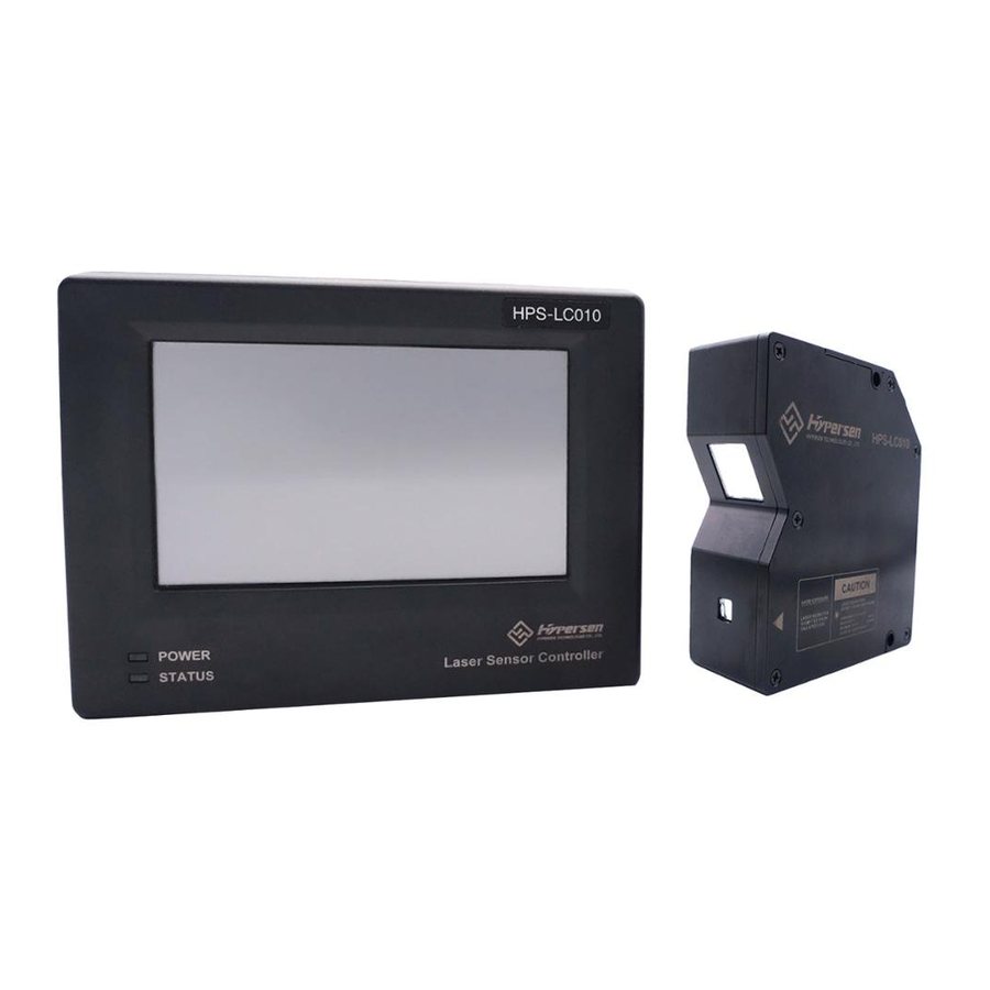
- Page 1 Hypersen Technologies Co., Ltd. HPS-LC010 HPS-LC010 High-Accuracy Laser Displacement Sensor User’s Manual September 2018 Rev.1.1 1/70...
-
Page 2: Introduction
Caution Ensuring safe operation • Be sure to turn off the power to the HPS-LC010 and connected devices when you connect/disconnect the cable to/from them. Failure to do so may result in product damage. • Do not turn off the power while any item is being set. Part or all of the settings may be lost. -
Page 3: Other Considerations
Hypersen Technologies Co., Ltd. HPS-LC010 Installation environment To use the HPS-LC010 properly and safely, avoid installing it in the following locations. Doing so may lead to product breakdown. • Location that is humid, dusty or poorly ventilated • Location where the temperature becomes high, such as a place exposed to direct sunlight •... -
Page 4: Precautions On Ce Marking
Hypersen Technologies Co., Ltd. HPS-LC010 Measurement target The measured value may be incorrect if the shape or surface condition of the target varies with individual targets. In this case, measure a known target and use the calibration function to correct the error. - Page 5 Hypersen Technologies Co., Ltd. HPS-LC010 • Install the laser product carefully so that the laser beam is not unintentionally directed at mirror-like surfaces. • Wear protective eye goggles appropriate for the laser beam wavelength. • Do not disassemble this product. Laser emission from this product is not automatically stopped when it is disassembled.
-
Page 6: Table Of Contents
Hypersen Technologies Co., Ltd. HPS-LC010 Content Introduction ................................. 2 Safety Preautions ............................... 2 General Precautions ..........................2 Warning ..............................2 Caution ............................... 2 Other considerations ..........................3 Precautions on CE Marking ........................4 Precautions on wiring ..........................4 Safety precautions on laser products ..................... 4 Chapter 1 Before use .............................. - Page 7 Hypersen Technologies Co., Ltd. HPS-LC010 Set communication method ........................26 Chapter 3 I/O Terminals ............................28 Names and Functions of the I/O Terminals ....................28 12-pin terminal block (Terminals) ......................28 Power Terminal ............................30 Function of the I/O signal ........................30 Input terminal configuration ..........................30...
- Page 8 Chapter 6 Specification ............................63 Specification ..............................63 Controller ..............................63 Sensor head ............................. 64 Dimension .................................65 HPS-LC010 controller ..........................65 HPS-LC010 sensor head ........................65 Appendix ...................................67 Troubleshooting ..............................67 Option list ................................69 Revision history ..............................69 Product warranty policy ............................70 September 2018 Rev.1.1...
-
Page 9: Chapter 1 Before Use
Hypersen Technologies Co., Ltd. HPS-LC010 Chapter 1 Before use System Configuration September 2018 Rev.1.1 9/70... -
Page 10: Checking The Package Contents
Hypersen Technologies Co., Ltd. HPS-LC010 Checking the Package Contents Ensure that all the components and accessories listed below are included in the package of the model you purchased before using the unit. September 2018 Rev.1.1 10/70... -
Page 11: Part Names And Functions
Hypersen Technologies Co., Ltd. HPS-LC010 Part Names and Functions Controller The items displayed on the detection value display and their meanings Display Meaning 99.9999 Exceed maximum range -99.9999 Exceed minimum range 88.8888 Insufficient light signal received Operation button Button Function •... -
Page 12: Sensor Head
Hypersen Technologies Co., Ltd. HPS-LC010 Sensor head (1) Laser emission LED, lights or flashes while the product is in operation. (2) Mounting holes (3) Connecting cable, connected to the head-to-controller cable. (4) Transmitter emits the laser beam, receiver receives the laser beam for measurement. Two parts work simultaneously for measurement this part is protected with a glass cover. -
Page 13: Mounting The Sensor Head According To The Measurement Target
Hypersen Technologies Co., Ltd. HPS-LC010 For both diffuse-reflection mounting and mirror-reflection mounting, the laser emission LED lights in green when the target is within approximately ±2.0 mm of the reference position, the laser emission LED lights in green flash when the target is in other positions within the reference position. The laser emission LED lights in red flash when the target is out of the reference position. -
Page 14: Mounting The Sensor Head
Hypersen Technologies Co., Ltd. HPS-LC010 CAUTION Do not block the ventilation holes on the top and bottom of the controller. The heat may stay inside and cause a malfunction. When the temperature inside the control panel exceeds the specified ambient temperature, decrease the temperature of the controller bottom to the specified ambient temperature or lower by using forced air cooling or by providing more clearance around the controller. - Page 15 Hypersen Technologies Co., Ltd. HPS-LC010 3: System time 4: Screen lock button Press this button can lock or unlock the touch screen. 5: Automatic zeroing button Shorly press can automatically zeroing, press it for 3 seconds can cancel automatically zeroing, return to absolute displacement mode (screen displays ABS icon).
-
Page 16: Chapter 2 Operations During Measurement
Hypersen Technologies Co., Ltd. HPS-LC010 Chapter 2 Operations during Measurement Set tolerance comparator value The function of the tolerance comparator setting You can set tolerance values (tolerance comparator values) used to decide whether the measured value is within the allowable range. The measured values are classified into three levels based on the tolerance: HI when the value exceeds the upper limit, LO when the value is below the lower limit, and GO when the value is within the allowable range. -
Page 17: Auto-Zero
Hypersen Technologies Co., Ltd. HPS-LC010 Auto-Zero The auto-zero function can be used to set a reference point at "0", for example, when the target is changed. You can instantaneously reset the currently displayed value to "0" by pressing the [ZERO] button or other operation. -
Page 18: Switch Program Number
Set measurement parameters Use filters to stabilize the measurement HPS-LC010 provides follwing 2 filters: Filter’s name Function Moving average filter Calculate the moving average of the measured values and set the number of measurements to obtain the average value. -
Page 19: Set The Average Filter
The following is an example of processing in which the average number of detection times is set to four. The actual sampling period and refresh cycle vary depending on the different measuring materials. Set measurement mode HPS-LC010 provides 6 measurement modes Below chart introduce these measurement modes, set these modes through controller interface or communication port command. - Page 20 Hypersen Technologies Co., Ltd. HPS-LC010 Mode name Description Measurement results displayed/output continuously Normal Measure maximum values during specified period Hold peak Measure minimum values during specified period Hold valley September 2018 Rev.1.1 20/70...
- Page 21 Hypersen Technologies Co., Ltd. HPS-LC010 Measure maximum and minimum values during specified period Peak-valley hold Measure specified moment’s value Sample hold Measure average value during specified value Average hold Note: Except normal mode, other five measurement modes require an input terminal configured for clock synchronization.
- Page 22 Hypersen Technologies Co., Ltd. HPS-LC010 Normal mode Note: The above figure shows an example where the level of the input/output port is set to active high. Peak hold September 2018 Rev.1.1 22/70...
- Page 23 Hypersen Technologies Co., Ltd. HPS-LC010 Valley hold Peak-peak hold September 2018 Rev.1.1 23/70...
-
Page 24: Data Storage Function
Sample hold Data storage function In the internal memory, HPS-LC010 can store up to 1,200,000 measured values. Send the command through the communication interface to read the stored data. This function stores the measured value in the controller's internal memory. -
Page 25: Set Data Storage
Hypersen Technologies Co., Ltd. HPS-LC010 3.Measured results will be stored in the internal memory 4.Stop storing measurement data according to “Condition for stop data storage” 5.After the data storage function is stopped, the measurement result is no longer stored, and the controller sends a "storage complete"... -
Page 26: Set Touch Screen Auto-Lock Time
Hypersen Technologies Co., Ltd. HPS-LC010 2. Press System button 3. Press Backlight input box, type in number (unit: second) on buttonboard, press Enter to confirm, press ESC to cancel input 4. Press Set button to save the settings Send Command #23 to set backlight overtime time through communication port Set touch screen auto-lock time 1. - Page 27 5. Press Set button to save the settings USB-S settings After the HPS-LC010 is connected to a PC, the USB-S interface will be virtualized as an Ethernet interface, which makes the secondary development on PC much easier. 1. Make sure USB-S does not connect to external device, if connect, please disconnect the physical connection 2.
-
Page 28: Chapter 3 I/O Terminals
Hypersen Technologies Co., Ltd. HPS-LC010 Chapter 3 I/O Terminals Names and Functions of the I/O Terminals 12-pin terminal block (Terminals) Terminal Number Signal definition Description COM_IN COM for input Input terminal 1 Input terminal 2 Input terminal 3 Input terminal 4... - Page 29 • Input port The input terminals of the HPS-LC010 are non-voltage input type, and the COM_IN terminal is a common terminal through a choke coil and 24V DC (-). When the IN and COM_IN terminals are short-circuited, the COM_IN terminal is in the input state. If the IN terminal is to be operated in the voltage input mode, the maximum input voltage is DC 28V.
-
Page 30: Power Terminal
PC internal parts and the SG (GND) terminal of the HPS-LC010. The 24VDC (-) terminal, the SG (GND) of the USB terminal, the SG (GND) and 24VDC (-) of the RS-232C interface, and the SG (GND) of the LAN port become the common ground through the corresponding chokes. -
Page 31: Configuration For Auto-Zero
Hypersen Technologies Co., Ltd. HPS-LC010 2. Press I/O Port button 3. Press the Input Port tab and set the desired terminal Note: When any input terminal is configured as "off" or "laser control function", if the input level signal does not match the set polarity, the corresponding terminal status lights in red. -
Page 32: Configuration For Clock Synchronization Function
Hypersen Technologies Co., Ltd. HPS-LC010 Timing diagram (when using rising edge trigger) Configuration for Clock Synchronization function After the external device and the terminal are connected, when any input terminal is configured as Clock Synchronization function, only a level signal is required to trigger the Clock Synchronization function. When the external devices do not have the LAN, USB or UART communication interfaces, this function will be very convenient. -
Page 33: Output Terminal Configuration
Hypersen Technologies Co., Ltd. HPS-LC010 Timing diagram (when using high level trigger) Output Terminal Configuration The output terminals can provide signal prompts during measurement. Some functions of the output terminals need to be used with a tolerance comparator. This product supports two configurations: Set through the controller interface 1.Press the... -
Page 34: Configuration For Lo Output
This product supports firmware upgrade function. Once the product's firmware is updated, it means that some bugs have been fixed or the performance has been improved. Please refer to the official website of Hypersen Technology (Shenzhen) Co., Ltd.: http://www.hypersen.com to see if there is a new firmware released. -
Page 35: Chapter 5 Communication Command
Hypersen Technologies Co., Ltd. HPS-LC010 Chapter 5 Communication Command This chapter describes the format of commands which can be used to communicate with the controller. The command can be received by the controller during measurement, and the controller will send back a command response after correctly processing the received command. -
Page 36: Commands
Hypersen Technologies Co., Ltd. HPS-LC010 Commands Command #1 Read Controller Version Information This command is used to read controller software version information Header 1 Header 2 Message Command high length bytes byte byte Byte0 Byte1 Byte2 Byte3 Byte4 Byte5 0x3F... -
Page 37: Command #3 Read Sensor Head Version Information
Hypersen Technologies Co., Ltd. HPS-LC010 Month Major version Small version Ammendment No. CRC high byte CRC low byte 0xF5: Message end 1 0x5F: Message end 2 Command #3 Read Sensor Head Version Information This command is used to read sensor head version information... -
Page 38: Command #5 Auto-Zero Or Cancel Auto-Zero
Hypersen Technologies Co., Ltd. HPS-LC010 Zero-offset value [15:8] Zero-offset value [7:0] CRC high byte CRC low byte Returned data: Byte number Description 0x5F: Header 1 0xF5: Header 2 0x00: Message length high byte 0x06: Message length low byte 0xB5: RID byte... -
Page 39: Command #6 Read Current Zero-Offset Value
Hypersen Technologies Co., Ltd. HPS-LC010 Command #6 Read Current Zero-Offset Value This command is used to read the current Zero-offset value. The returned value = real value *1000000. Header1 Header2 Message Command high length byte byte byte Byte0 Byte1 Byte2... -
Page 40: Command #8 Continuous Measurement
Hypersen Technologies Co., Ltd. HPS-LC010 CRC low byte 0xF5: Message end 1 0x5F: Message end 2 Command #8 Continuous Measurement This command is used to activate the controller to continuously output the measured results. The returned value = real value *1000000. -
Page 41: Command #9 Program Setting
Hypersen Technologies Co., Ltd. HPS-LC010 In peak-peak hold mode, the format of data packet is as below: Header1 Header2 Message Measured value CRC16 Message end Message end length Minimum value 1[31:0] Maximum value 1[31:0] 0x5F 0xF5 [15:0] 0xFD … [15:0]... -
Page 42: Command #10 Set Or Read Current Program Number
Hypersen Technologies Co., Ltd. HPS-LC010 0x00: Message length high byte 0x06: Message length low byte 0xA8: RID byte 0x01: Confirmation byte 0x99: CRC high byte 0xF9: CRC low byte 0xF5: Message end 1 0x5F: Message end 2 Returned data of Read Command:... -
Page 43: Command #11 Set Or Read Laser Status
Hypersen Technologies Co., Ltd. HPS-LC010 Program number 0~9, for read command, this byte can be neglected CRC high byte CRC low byte Returned data: Byte number Description 0x5F: Header 1 0xF5: Header 2 0x00: Message length high byte 0x06: Message length low byte... -
Page 44: Command #12 Set Or Read Measurement Mode
Hypersen Technologies Co., Ltd. HPS-LC010 Returned data of Read Command: Byte No. Description 0x5F: Header 1 0xF5: Header 2 0x00: Message length high byte 0x08: Message length low byte 0xA9: RID byte 0x00: Laser is OFF status, 0x01: Laser is ON status... -
Page 45: Command #13 Set Or Read Data Storage Parameters
Hypersen Technologies Co., Ltd. HPS-LC010 CRC high byte CRC low byte 0xF5: Message end 1 0x5F: Message end 2 Returned data of Read Command: Byte No. Description 0x5F: Header 1 0xF5: Header 2 0x00: Message length high byte 0x09: Message length low byte... -
Page 46: Command #14 Start Or Stop Data Storage
Hypersen Technologies Co., Ltd. HPS-LC010 0x06: Message length low byte 0xAF: RID byte 0x01: Confirmation byte CRC high byte CRC low byte 0xF5: Message end 1 0x5F: Message end 2 Returned data of Read Command: Byte No. Description 0x5F:Header1 0xF5:Header2... -
Page 47: Command #15 Read Saved Data
Hypersen Technologies Co., Ltd. HPS-LC010 Returned data of Set Command: Byte No. Description 0x5F: Header 1 0xF5: Header 2 0x00: Message length high byte 0x06: Message length low byte 0xAF: RID byte 0x01: Confirmation byte CRC high byte CRC low byte... -
Page 48: Command #16 Read Stored Data
Hypersen Technologies Co., Ltd. HPS-LC010 0x09: Message length low byte 0xB0: RID byte Storage quantity [31:24] Storage quantity [23:16] Storage quantity [15:8] Storage quantity [7:0] CRC high byte CRC low byte 0xF5: Message end 1 0x5F: Message end 2 Command #16 Read Stored Data This command is used to read the stored data and can specify the data length and start position for each read. -
Page 49: Command #17 Set Or Read Input Port Configuration
Hypersen Technologies Co., Ltd. HPS-LC010 Command #17 Set or Read Input Port Configuration This command is used to set or read the configuration and parameters of the IN port. The setting values will be automatically saved to the internal non-volatile memory and reloaded with each power up. -
Page 50: Command #18 Set Or Read Output Port Configuration
Hypersen Technologies Co., Ltd. HPS-LC010 Polarity: 0x00: low active, 0x01: high active CRC high byte CRC low byte 0xF5: Message end 1 0x5F: Message end 2 Command #18 Set or Read Output Port Configuration This command is used to set or read the configuration and parameters of the OUT port. The setting values will be automatically saved to the internal non-volatile memory and reloaded with each power up. -
Page 51: Command #19 Set Or Read Filter Parameters
Hypersen Technologies Co., Ltd. HPS-LC010 0xB2: RID byte Port number Function: 0x00: OFF, 0x05: Alarm, 0x06: GO, 0x07: HI, 0x08: LO Polarity: 0x00: low active, 0x01: high active CRC high byte CRC low byte 0xF5: Message end 1 0x5F: Message end 2 Command #19 Set or Read Filter Parameters This command is used to set or read the filter parameters. -
Page 52: Command #20 Set Or Read Controller Sampling Times
Hypersen Technologies Co., Ltd. HPS-LC010 CRC high byte CRC low byte 0xF5: Message end 1 0x5F: Message end 2 Returned data of Read Command: Byte No. Description 0x5F: Header 1 0xF5: Header 2 0x00: Message length high byte 0x0A: Message length low byte... -
Page 53: Command#21 Set Or Read Alarm Source
Hypersen Technologies Co., Ltd. HPS-LC010 0x06: Message length Low byte 0xB6: RID byte 0x01: Confirmation byte CRC high byte CRC low byte 0xF5: Message end 1 0x5F: Message end 2 Returned data of Read Command: Byte No. Description 0x5F: Header 1... -
Page 54: Command #22 Set Or Read Backlight Brightness Value
Hypersen Technologies Co., Ltd. HPS-LC010 CRC high byte CRC low byte 0xF5: Message end1 0x5F: Message end2 Returned data of Read Command: Byte No. Description 0x5F: Header 1 0xF5: Header 2 0x00: Message length high byte 0x06: Message length low byte... -
Page 55: Command #23 Set Or Read Backlight Timeout
Hypersen Technologies Co., Ltd. HPS-LC010 Returned data of Read Command: Byte No. Description 0x5F: Header 1 0xF5: Header 2 0x00: Message length high byte 0x06: Message length low byte 0xBA: RID byte Backlight brightness value [7:0] CRC high byte CRC low byte... -
Page 56: Command #24 Set Or Read Screen Lock Time
Hypersen Technologies Co., Ltd. HPS-LC010 Returned data of Read Command: Byte No. Description 0x5F: Header 1 0xF5: Header 2 0x00: Message length high byte 0x07: Message length low byte 0xB8: RID byte Timeout time [7:0] Timeout time [15:8] CRC high byte... - Page 57 Hypersen Technologies Co., Ltd. HPS-LC010 Returned data of Read Command: Byte No. Description 0x5F: Header 1 0xF5: Header 2 0x00: Message length high byte 0x07: Message length low byte 0xB9: RID byte Lock time [7:0] Lock time [15:8] CRC high byte...
-
Page 58: Crc16 C Language Implementation
Hypersen Technologies Co., Ltd. HPS-LC010 CRC16 C language implementation The CRC16 algorithm used in the command packet and returned data packet is the standard CRC16- CCITT, the polynomial coefficient is 0x1021, and the initial value is 0xffff. There are three examples of... - Page 59 Hypersen Technologies Co., Ltd. HPS-LC010 ############################################################# Implementation2: ############################################################# #include<stdio.h> Flash space requirement: medium Calculating speed: medium /*FunctionName:crc_cal_by_halfbyte//CalculateCRCbyhalfbyte FunctionParameters:unsignedchar*ptr//Pointerofdatabuffer unsignedcharlen//Lengthofdata ReturnValue:unsignedint Polynomial:CRC-CCITT0x1021 unsignedintcrc_cal_by_halfbyte(unsignedchar*ptr,unsignedcharlen) unsignedshortcrc=0xffff; while(len--!=0) unsignedcharhigh=(unsignedchar)(crc/4096); crc<<=4; crc^=crc_ta_4[high^(*ptr/16)]; high=(unsignedchar)(crc/4096); crc<<=4; crc^=crc_ta_4[high^(*ptr&0x0f)]; ptr++; returncrc; unsignedintcrc_ta_4[16]={/*CRChalfbytetable*/ 0x0000,0x1021,0x2042,0x3063,0x4084,0x50a5,0x60c6,0x70e7, 0x8108,0x9129,0xa14a,0xb16b,0xc18c,0xd1ad,0xe1ce,0xf1ef, September 2018 Rev.1.1 59/70...
- Page 60 Hypersen Technologies Co., Ltd. HPS-LC010 ############################################################# Implementation3: ############################################################# #include<stdio.h> Flash space requirement: high Calculating speed: fast /*FunctionName:crc_cal_by_byte//CalculateCRCbyhalfbyte FunctionParameters:unsignedchar*ptr//Pointerofdatabuffer unsignedcharlen//Lengthofdata ReturnValue:unsignedint Polynomial: CRC-CCITT0x1021 unsignedintcrc_ta_8[256] = {/*CRCbytetable*/ 0x0000,0x1021,0x2042,0x3063,0x4084,0x50a5,0x60c6,0x70e7, 0x8108,0x9129,0xa14a,0xb16b,0xc18c,0xd1ad,0xe1ce,0xf1ef, 0x1231,0x0210,0x3273,0x2252,0x52b5,0x4294,0x72f7,0x62d6, 0x9339,0x8318,0xb37b,0xa35a,0xd3bd,0xc39c,0xf3ff,0xe3de, 0x2462,0x3443,0x0420,0x1401,0x64e6,0x74c7,0x44a4,0x5485, 0xa56a,0xb54b,0x8528,0x9509,0xe5ee,0xf5cf,0xc5ac,0xd58d, 0x3653,0x2672,0x1611,0x0630,0x76d7,0x66f6,0x5695,0x46b4, 0xb75b,0xa77a,0x9719,0x8738,0xf7df,0xe7fe,0xd79d,0xc7bc, 0x48c4,0x58e5,0x6886,0x78a7,0x0840,0x1861,0x2802,0x3823, 0xc9cc,0xd9ed,0xe98e,0xf9af,0x8948,0x9969,0xa90a,0xb92b, 0x5af5,0x4ad4,0x7ab7,0x6a96,0x1a71,0x0a50,0x3a33,0x2a12, 0xdbfd,0xcbdc,0xfbbf,0xeb9e,0x9b79,0x8b58,0xbb3b,0xab1a, 0x6ca6,0x7c87,0x4ce4,0x5cc5,0x2c22,0x3c03,0x0c60,0x1c41, 0xedae,0xfd8f,0xcdec,0xddcd,0xad2a,0xbd0b,0x8d68,0x9d49, 0x7e97,0x6eb6,0x5ed5,0x4ef4,0x3e13,0x2e32,0x1e51,0x0e70,...
- Page 61 Hypersen Technologies Co., Ltd. HPS-LC010 0xcb7d,0xdb5c,0xeb3f,0xfb1e,0x8bf9,0x9bd8,0xabbb,0xbb9a, 0x4a75,0x5a54,0x6a37,0x7a16,0x0af1,0x1ad0,0x2ab3,0x3a92, 0xfd2e,0xed0f,0xdd6c,0xcd4d,0xbdaa,0xad8b,0x9de8,0x8dc9, 0x7c26,0x6c07,0x5c64,0x4c45,0x3ca2,0x2c83,0x1ce0,0x0cc1, 0xef1f,0xff3e,0xcf5d,0xdf7c,0xaf9b,0xbfba,0x8fd9,0x9ff8, 0x6e17,0x7e36,0x4e55,0x5e74,0x2e93,0x3eb2,0x0ed1,0x1ef0 unsignedintcrc_cal_by_byte (unsignedchar*ptr, unsignedcharlen) unsignedshortcrc=0xffff; while (len--! =0) unsignedinthigh=(unsignedint)(crc/256); crc<<=8; crc^=crc_ta_8[high^*ptr]; ptr++; returncrc; ############################################################# TestingCode: ############################################################# voidmain () unsignedcharsample_data[]={0x01,0x01,0x01,0x06,0xd9,0xfc,0x8c,0x02,0x01,0x00,0x01};//Resultshould be:0x9b94 unsignedchardata1[]={0x63};//Resultshouldbe:0xbd35 unsignedchardata2[]={0x8c};//Resultshouldbe:0xb1f4 unsignedchardata3[]={0x7d};//Resultshouldbe:0x4eca unsignedchardata4[]={0xaa,0xbb,0xcc};//Resultshouldbe:0x6cf6 unsignedchardata5[]={0x00,0x00,0xaa,0xbb,0xcc};//Resultshouldbe:0xb166 unsignedshortr1=0,r2=0,r3=0,r4=0,r5=0,r_sample_data; //Implementation1 r1=crc_cal_by_byte(data1,1); r2=crc_cal_by_byte(data2,1); r3=crc_cal_by_byte(data3,1);...
- Page 62 Hypersen Technologies Co., Ltd. HPS-LC010 e_data); r1=r2=r3=r4=r5=0; //Implementation2 r1=crc_cal_by_bit(data1,1); r2=crc_cal_by_bit(data2,1); r3=crc_cal_by_bit(data3,1); r4=crc_cal_by_bit(data4,3); r5=crc_cal_by_bit(data5,5); r_sample_data=crc_cal_by_bit(sample_data,11); printf("Implementation_2:r1=%x,r2=%x,r3=%x,r4=%x,r5=%x,r_sample_data=%x\n",r1,r2,r3,r4,r5,r_sampl e_data); r1=r2=r3=r4=r5=0; //Implementation3 r1=crc_cal_by_halfbyte(data1,1); r2=crc_cal_by_halfbyte(data2,1); r3=crc_cal_by_halfbyte(data3,1); r4=crc_cal_by_halfbyte(data4,3); r5=crc_cal_by_halfbyte(data5,5); r_sample_data=crc_cal_by_halfbyte(sample_data,11); printf("Implementation_3:r1=%x,r2=%x,r3=%x,r4=%x,r5=%x,r_sample_data=%x\n",r1,r2,r3,r4,r5,r_sampl e_data); r1=r2=r3=r4=r5=0; ############################################################# September 2018 Rev.1.1 62/70...
-
Page 63: Chapter 6 Specification
Hypersen Technologies Co., Ltd. HPS-LC010 Chapter 6 Specification Specification Controller Model Type HPS-LC010 Power voltage DC 12V~26V, typical DC24V Power supply Maximum current Number of sensor heads suppotred Power consumption 5W (Typical) Working temperature 0~50℃ Relative humidity 35 to 85%RH (No condensation) -
Page 64: Sensor Head
Hypersen Technologies Co., Ltd. HPS-LC010 Sensor head Model HPS-LC010 Reference distance 55mm±0.5mm Measuring range ±10mm Install mode Diffuse reflection, mirror reflection Wavelength: 655nm Light source Laser power: <0.48mW. Laser classification: Class II Laser beam diameter Ø30µm (At reference distance) Linearity Full scale ±0.025% (F.S.=20mm) -
Page 65: Dimension
Hypersen Technologies Co., Ltd. HPS-LC010 Dimension HPS-LC010 controller HPS-LC010 controller dimension drawings (unit: mm) HPS-LC010 sensor head (unit: mm) September 2018 Rev.1.1 65/70... - Page 66 Hypersen Technologies Co., Ltd. HPS-LC010 Beam diameter <unit: mm> If the interfering object is outside the range of the spot, it does not affect the detection. September 2018 Rev.1.1 66/70...
-
Page 67: Appendix
Hypersen Technologies Co., Ltd. HPS-LC010 Appendix Troubleshooting This section provides countermeasures for errors or problems that may occur during the operation of the HPS- LC010. Problem Probable reason Countermeasure Nothing appears on the power line properly Correctly connect power cable... - Page 68 Hypersen Technologies Co., Ltd. HPS-LC010 Is the measurement target or sensor Take appropriate measures such head vibrating? as vibration isolation Is the peak -peak hold measurement The peak-peak hold mode outputs mode enabled? the maximum and minimum values for the specified time period at the same time, so fluctuations occur, which is normal.
-
Page 69: Option List
Hypersen Technologies Co., Ltd. HPS-LC010 Option list The following table lists the HPS-LC010 supported options Name Type Application RS-232C cable CB-RS232E Communication cable for RS-232C (2.5m) USB cable CB-USB USB connection cable (2m) Ethernet cable CB-LAN Ethernet communication crossover cable (3m) -
Page 70: Product Warranty Policy
• Public utilities such as electricity, gas and water services • Outdoor use of similar conditions or environment 4. Contact Hypersen Technologies (Shenzhen) Co., Ltd. A425, Baoan Intelligence Valley, No.4 Yintian Rd., Xixiang Street, Baoan Dist., Shenzhen City, Guangdong Province, China...
Need help?
Do you have a question about the HPS-LC010 and is the answer not in the manual?
Questions and answers