Table of Contents
Advertisement
Advertisement
Table of Contents

Related Manuals for Ubiquiti UniFi UAS-XG


Summary of Contents for Ubiquiti UniFi UAS-XG
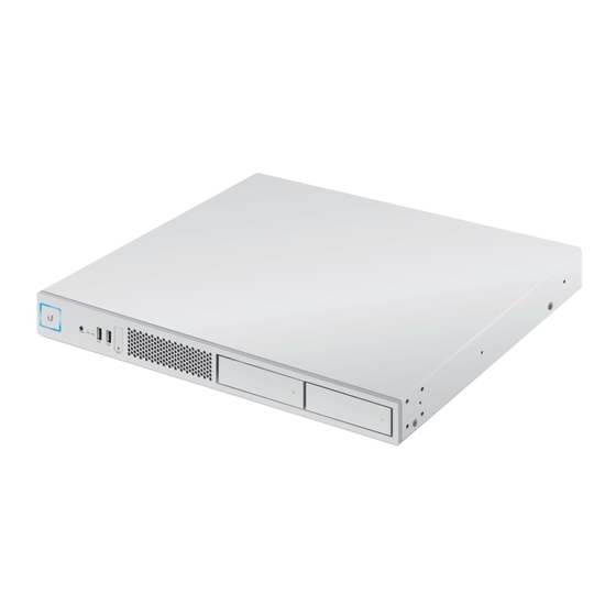
- Page 1 10G Rack-Mountable Application Server Model: UAS-XG...
-
Page 2: Package Contents
Introduction Thank you for purchasing the Ubiquiti® UniFi® Application Server. This Quick Start Guide is designed to guide you through installation and also includes warranty terms. Package Contents UniFi Application Server Rack-Mount Brackets Bracket Screws Mounting Screws (Qty. 2) (Qty. 8) (Qty. - Page 3 Network Topology Example The UniFi Server requires a DHCP-enabled network to obtain an IP address. Here is a sample network diagram using these devices: UAS-XG • The UniFi Application Server hosts the UniFi Network Controller and UniFi Video software applications. • US-16-XG Connect the 10G Ethernet ports from the UAS-XG to the US-16-XG or other 10G-capable switches for...
-
Page 4: Hardware Overview
Hardware Overview Back Panel Ports IPMI LAN LAN1-2 Power USB1-2 Port Description Connect the included Power Cord to the Power Power port. (Optional) The dedicated RJ45 port supports IPMI LAN IPMI (Intelligent Platform Management Interface) for monitoring and control. (Optional) Connect USB 3.0 devices. Maximum USB1-2 power per port is 5W (5V, 1A). - Page 5 Back Panel LEDs IPMI IPMI LAN2 LAN2 Link Activity Activity Speed LAN1 LAN1 Activity Speed IPMI LAN LEDs State Status No Link Link Amber Link Established No Activity Activity Activity LAN1/2 LEDs State Status No Link Activity Amber Flashing Indicates Activity No Connection or Link Established at 10/100 Mbps Speed...
- Page 6 Front Panel LEDs LAN1/2 System HDD1/2 System LED Color State Status White Flashing Initializing Blue Steady Functioning Properly LAN1/2 LEDs Color State Status Steady Link Established at 1/10 Gbps Green Flashing Indicates Activity HDD1/2 LEDs Color State Status Green Flashing Indicates Read/Write Activity Amber Steady...
- Page 7 Front Panel Ports USB3/4 USB3-4 (Optional) Connect USB 2.0 devices. Maximum power per port is 5W (5V, 1A). Front Panel Buttons Power Reset Button Description Power Press to turn the UniFi Server on or off. The UniFi Server should be running after bootup Reset is complete, and the System LED is blue.
- Page 8 Front Panel HDD Bays One 8 TB HDD is pre-installed. If you want to replace the HDD, follow these instructions: 1. Before replacing the HDD, ensure that the UniFi Server is powered off to prevent any software disruption. 2. To replace the HDD, press the HDD bay door. 3.
-
Page 9: Before You Begin
Before You Begin Remove the labels that secure the HDD bay doors. 1. Before removing the labels, ensure that the UniFi Server is powered off to avoid disconnecting the hard drives while the UniFi Server is powered on. 2. Pull the white part of the label. 3. - Page 10 4. Once the door is released, rotate the door and pull the HDD bay out. 5. Remove the rest of the label. 6. Push the HDD bay back in and close the HDD bay door. 7. Repeat steps 2-6 for the other label.
-
Page 11: Hardware Installation
Hardware Installation The UniFi Server can be placed on a horizontal surface, mounted on a wall, or mounted in a rack. Mounting in a Rack (Optional) 1. Attach the Rack-Mount Brackets to the UniFi Server using the eight Bracket Screws. 2. Attach the UniFi Server to the rack using the four Mounting Screws. -
Page 12: Connecting Power
Connecting Power 1. Connect the Power Cord to the Power port of the UniFi Server. 2. Connect the other end of the Power Cord to a UPS (Uninterruptible Power Supply) to prevent possible data loss from power outages. - Page 13 3. Press the Power button to turn on the UniFi Server.
-
Page 14: Connecting Ethernet
Connecting Ethernet 1. Connect an Ethernet cable from your switch to the LAN1 port of the UniFi Server. Note: We recommend connecting to the bottom port, LAN1, if you are only connecting a single Ethernet cable. 2. For an aggregate link, connect another Ethernet cable from your switch to the top port, LAN2, of the UniFi Server. -
Page 15: Initial Setup Via Bluetooth
Connecting VGA The VGA port is only used for console access in conjunction with a USB keyboard; it does not need to be connected for normal operation of the UniFi Server. 1. (Optional) Connect a VGA cable (not included) from your monitor to the VGA port of the UniFi Server. - Page 16 4. Tap Add Controller. 5. When the UniFi Server has been discovered, tap Set up this controller.
- Page 17 6. Configure the following settings: • Use SSO Credentials Toggle On. Note: To manually configure the credentials, tap See credentials in detail and go to step 7. Email • Enter your email address. Username • Enter the username for your UBNT Single Sign-On (SSO) account.
- Page 18 7. Configure the UniFi Controller, UniFi Video NVR, SSH, and/or IPMI credentials as needed: • Username Enter the appropriate username. Note: For the SSH and IPMI credentials, the username is always ubnt and cannot be changed. • Password Enter the appropriate password. Tap the icon to display the password in plaintext.
- Page 19 8. You will be notified when the settings have been saved. Tap Done. The username and password you configure in the UniFi Network app will be used for the pre-installed UniFi Network Controller and UniFi Video software.
- Page 20 UniFi Software The UniFi Network Controller and UniFi Video software applications are pre-installed on the UniFi Server. Follow these instructions to launch either software: 1. Ensure that your host system is on the same Layer-2 network as the UniFi Server. 2.
-
Page 21: Specifications
Specifications UAS-XG Dimensions 442.4 x 305.5 x 43.7 mm (17.42 x 12.03 x 1.72") Weight 6.5 kg (14.33 lb) With Mount Brackets 6.6 kg (14.55 lb) Max. Power Consumption 150W Power Method 100-240VAC/50-60 Hz, Universal Input Power Supply 100-240VAC, 2 to 4A, 50 to 60 Hz Supported Voltage Range 100-240VAC LEDs... -
Page 22: Safety Notices
Safety Notices Read, follow, and keep these instructions. Heed all warnings. Only use attachments/accessories specified by the manufacturer. WARNING: Do not use this product in location that can be submerged by water. WARNING: Avoid using this product during an electrical storm. - Page 23 Compliance Changes or modifications not expressly approved by the party responsible for compliance could void the user’s authority to operate the equipment. This device complies with Part 15 of the FCC Rules. Operation is subject to the following two conditions. This device may not cause harmful interference, and This device must accept any interference received, including interference that may cause undesired operation.
-
Page 24: Radiation Exposure Statement
IMPORTANT NOTE: Radiation Exposure Statement: • This equipment complies with radiation exposure limits set forth for an uncontrolled environment. • This equipment should be installed and operated with minimum distance 20 cm between the radiator and your body. • This transmitter must not be co-located or operating in conjunction with any other antenna or transmitter. - Page 25 RoHS/WEEE Compliance Statement English European Directive 2012/19/EU requires that the equipment bearing this symbol on the product and/or its packaging must not be disposed of with unsorted municipal waste. The symbol indicates that this product should be disposed of separately from regular household waste streams.
-
Page 26: Declaration Of Conformity
EU izjave o sukladnosti dostupan je na sljedećoj internetskoj adresi: ui.com/compliance Čeština [Czech] UBIQUITI tímto prohlašuje, že toto UAS-XG zařízení, je ve shodě se základními požadavky a dalšími příslušnými ustanoveními směrnic 2014/53/EU, 2014/30/EU, 2014/35/EU. Úplné znění EU prohlášení o shodě je k dispozici na této internetové adrese: ui.com/compliance Dansk [Danish] Hermed, UBIQUITI, erklærer at denne UAS-XG enhed, er i overensstemmelse med... - Page 27 English Hereby, UBIQUITI, declares that this UAS-XG device, is in compliance with the essential requirements and other relevant provisions of Directives 2014/53/EU, 2014/30/EU, 2014/35/EU. The full text of the EU declaration of conformity is available at the following internet address: ui.com/compliance...
-
Page 28: Online Resources
New York, NY 10017 ©2018-2019 Ubiquiti Inc. All rights reserved. Ubiquiti, Ubiquiti Networks, the Ubiquiti U logo, the Ubiquiti beam logo, and UniFi are trademarks or registered trademarks of Ubiquiti Inc. in the United States and in other countries. Apple and the Apple logo are trademarks of Apple Inc., registered in the U.S.
Need help?
Do you have a question about the UniFi UAS-XG and is the answer not in the manual?
Questions and answers