Table of Contents
Advertisement
Quick Links
__________________________________________________________________________________________________________
Where should a Gas Detector be fitted?
A gas detector should be fitted in the room where a gas escape is most likely to occur.
For most installations the most likely source of a gas escape will be the cooker in the kitchen.
Choosing a Location
Natural gas is lighter than air therefore the gas detector should be wall mounted above
the level of a possible gas escape but not more than 30cm from the ceiling.
The gas detector should be located between 1 and 5 metres from the gas appliance. It must not be located inside a cupboard,
behind a curtain, directly above the cooker or sink, next to a door or window or near an extractor fan.
The gas detector should be within 5 metres of a mains supply otherwise the cable provided will need replacing.
Typical Tools Required
Be careful when using step ladders – always face the direction you are working.
Always make sure the correct drill bits and screwdrivers are used.
Installation
1.
IMPORTANT: BS EN50244:2016 Electrical apparatus for
the detection of combustible gases in domestic
premises states that gas detectors should be installed
via a permanent electrical connection and not using
a plug and socket.
2.
Fix the mounting plate complete with detector
to the wall using the screws and plugs provided
through the FIXING HOLES "A".
3.
Run the mains cable to the nearest mains supply and
secure using the self-adhesive cable clips provided.
4.
The detector should be wired to the mains supply using a
flexible cable appropriately rated via a fused connection
outlet and fitted with a 3A fuse to BS1363-4 and BS1362
respectively, or according to local regulations.
5.
If choosing to use a plug and socket then fit the plug-wrap,
plug-in and switch on the mains supply.
Check the following sequence occurs; all 3 indicators light
and the unit sounds a single chirp. The 3 indicators then
light in turn and cycle 4 times. The unit is operating
when the
GREEN
Power light is lit steady.
6.
Press and hold the TEST/HUSH button for 1 second.
The red light will flash 4 times followed by the yellow
light 4 times accompanied by the audible alarm
sounding 8 times.
Doc No. FM0725 issue C Page 1
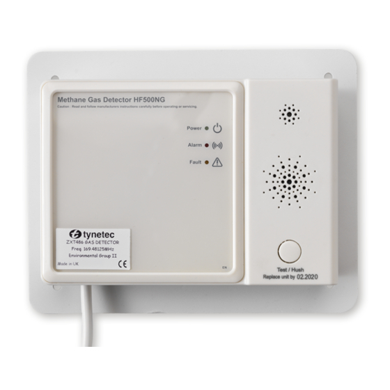
169MHz Telecare Devices
Gas Detector
•
Compatible with Reach at-home alarms, Advent xt warden call,
Altec Response and Touchsafe Pro Nursecall systems
•
Alarm at 10% of LEL (Lower Explosive Limit)
•
85dB @ 1m sounder
•
3 Indicator lights: green power, red alarm & yellow fault
•
Requires 240V AC mains supply
•
Power consumption: <6.5 Watts
•
Transmitter low battery warning
•
Test/Hush button
•
Complies with EN50194:1:2009
•
Backplate dimensions: 175 x 140mm (depth = 43mm)
•
Weight: 375 grams
•
Product Code: ZXT486
"A"
"A"
FIT PLUG
WRAP
Northumberland, NE24 5TF. Tel:
4 x FIXING HOLES
"A"
Tynetec and Aidcall are business units of Legrand Electric Ltd
Unit 10 Cowley Road, Blyth Riverside Business Park, Blyth
01670 352 371
Email:
sales@tynetec.co.uk Web: www.tynetec.co.uk
"A"
GAS ENTRY
POINT
AUDIBLE
ALARM
TEST/HUSH
BUTTON
REPLACE
BY DATE
"A"
INDICATOR LIGHTS
Fax:
01670 362 807
Advertisement
Table of Contents

Related Manuals for LEGRAND Tynetec Aidcall ZXT486


Summary of Contents for LEGRAND Tynetec Aidcall ZXT486
- Page 1 The red light will flash 4 times followed by the yellow light 4 times accompanied by the audible alarm sounding 8 times. Tynetec and Aidcall are business units of Legrand Electric Ltd Unit 10 Cowley Road, Blyth Riverside Business Park, Blyth Northumberland, NE24 5TF. Tel:...
- Page 2 Testing & Registering the Gas Detector Press and hold the Test/Hush button for 1 second to verify operation – this should be done once a month. Press and hold the Test/Hush button for more than 20 seconds then release to test the radio transmitter, this must be done when registering the gas detector onto the warden call system, at-home alarm or Nursecall system.
- Page 3 Registering a Gas Detector onto a Reach at-home alarm unit 1. Put the Reach unit into radio device learn mode… “Trigger GREEN Press and HOLD the button on the Reach unit. Radio Device” When the front light FLASHES FAST GREEN release the ...
- Page 4 Registering a Gas Detector onto an Advent xt warden call system 1. Put the Advent xt system into radio device learn mode… “Ready” Using the Manager’s DECT telephone; Press the LINE key and wait for the “Ready” prompt. Enter 5 0 0 0 followed by the key. Enter the flat number the gas detector is being installed in followed by the ...
- Page 5 Registering a Gas Detector onto an Altec Response local carer alarm unit 1. Put the Altec Response unit into radio device learn mode… tynetec Press ENTER to activate the wake-up display then ENTER again to display the main menu. Radio Devices Press ENTER to select...
- Page 6 Registering a Gas Detector onto a Touchsafe Pro Nursecall system 1. Put the Touchsafe Pro Master Panel into Telecare registration mode; touch the screen and Logon as an Engineer or a Manager (password required), then from the main menu page touch the Telecare button to open the screen shown below…...
Need help?
Do you have a question about the Tynetec Aidcall ZXT486 and is the answer not in the manual?
Questions and answers